Process Variation & RC corner
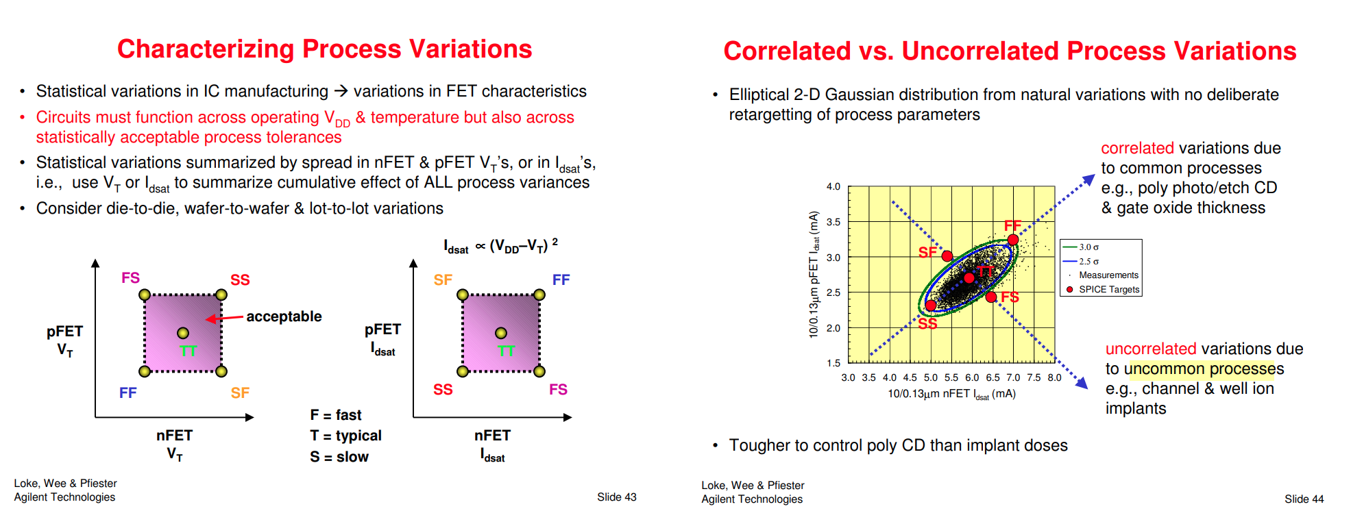
Process Variation

[https://ewh.ieee.org/r5/denver/sscs/Presentations/2004_12_Loke.pdf]
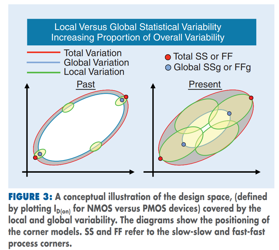
Global/Local Variation

Timing and RC Modeling with Process Corners

Global and Local variation by Gaussian
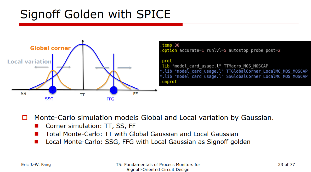
Local Monte-Carlo (SSG, FFG with Local Gaussian) as Signoff golden
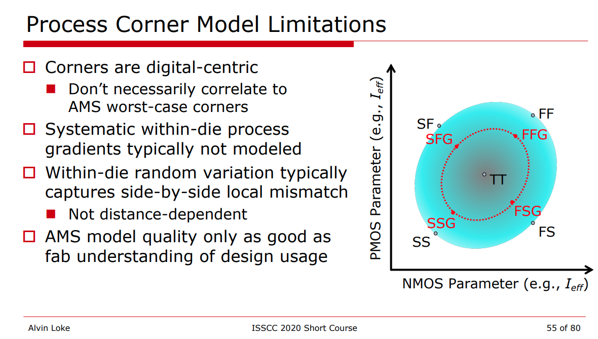
Process Corner Model Limitations
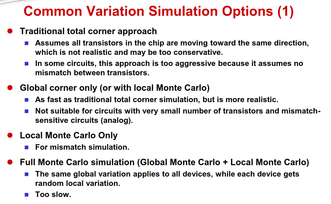
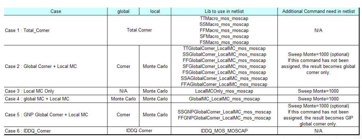
Variation section
- Total corner (TT/SS/FF/SF/FS)
- E.g. TTMacro_MOS_MOS_MOSCAP
- Global Corner (TTG/SSG/FFG/SFG/FSG) + Local MC
- E.g. TTGlobalCorner_LocalMC_MOS_MOSCAP
- Local MC
- E.g. LocalMCOnly_MOS_MOSCAP
- Global MC + Local MC (Total MC)
- GlobalMC_LocalMC_MOS_MOSCAP

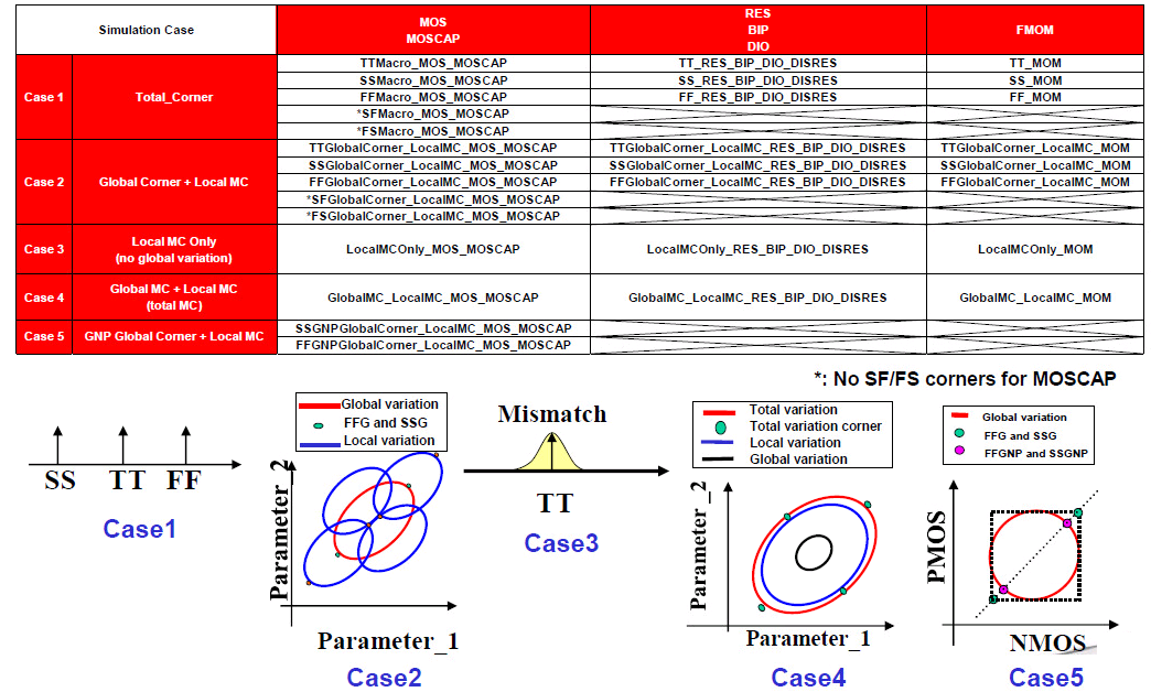
SSGNP, FFGNP:
When N/P global correlation is weak (R^2=0.15), the corner of N/PMOS balance circuit (e.g. inverter) can be tightened (3sigma -> 2.5sgma) due to the cancellation between NMOS and PMOS
SSGNP, FFGNP usually used in Digital STA
- Global variation validation with global corner
- 3-sigma of global MC simulation is aligned with global corner
- Total variation validation with total corner
- 3-sigma of global MC + local MC (total) simulation is aligned with total corner
Global Corner
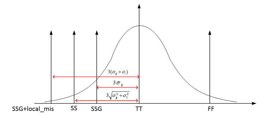
The "total corner" is representative of the maximum device parameter variation including local device variation effects. However, it is not a statistical corner.
The "global" corner is defined as the "total" corner minus the impact of "local variation"
Hence, if you were to examine simulation results for a parameter using a "total" and "global" corner, you would find the range of variation will be less with the "global" corner than with the "total" corner.
The "global" corner is provided for use in statistical simulations. Hence, when performing a Monte-Carlo simulation, the "global" corner is selected - NOT the "total" corner.
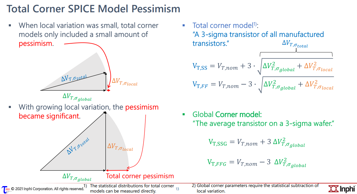
\[ \Delta V_{T,\sigma_{total}} = \sqrt{\Delta^2 _{T, \sigma_{global}}+\Delta^2 _{T, \sigma_{local}}} \]
RC corner
Traditional RC Corners
Metal width variation (\(\Delta W\)), Metal thickness variation (\(\Delta T\)), IMD thickness variation (\(\Delta H\))
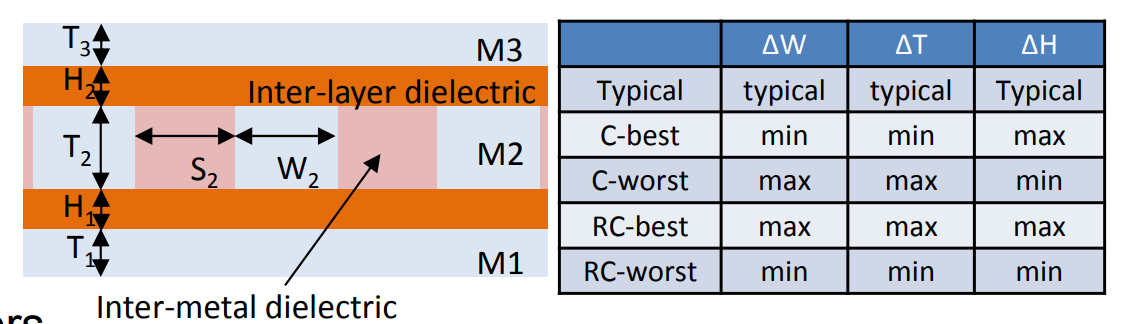
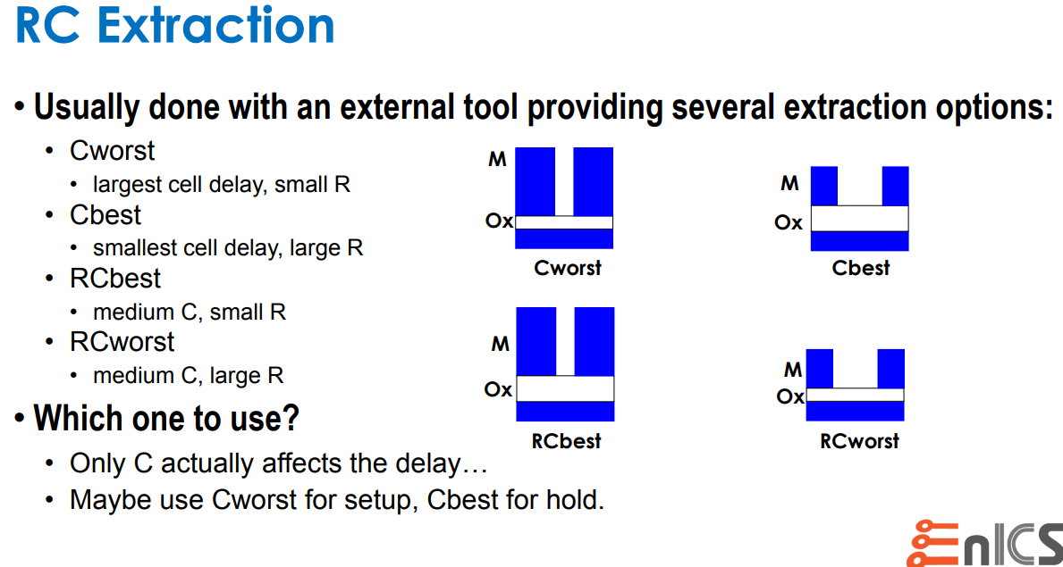
Capacitance Dominant: C-best, C-worst
Resistance Dominant: RC-best, RC-worst
DPT effect
When using two masks per layer (Double Patterning Technology, DPT) there is an issue of mask alignment where any mis-alignment will cause layer spacing values to change, therefore changing the parasitic coupling capacitance values.
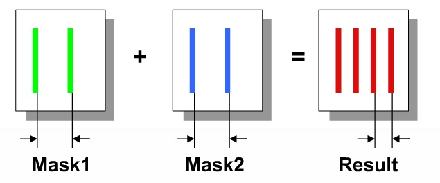

Misalignment scale and direction are not deterministic facts: coupling cap and total cap may be increased or decreased.
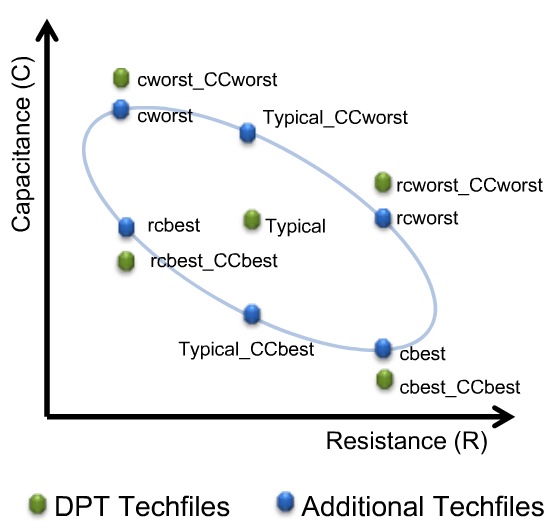
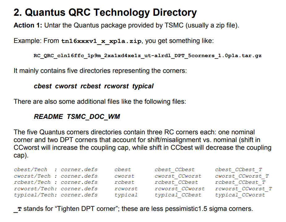
Five new corners are added in a DPT flow to account for RC variations accurately:

sapced-dependent side-wall dielectric constant also affect coupling cap
and CC_worst means to increase both K1 and K2
CC_best means to decrease both K1 and K2
Setup time sign-off would use:
Cworst_CCworst / RCworst_CCworst
Hold time sign-off would use:
Cbest_CCbest / RCbest_CCbest / Cworst_CCworst / RCworst_CCworst

Signoff corner
| with misalignment effect | without misalignment effect |
|---|---|
| cworst_CCworst, cworst_CCworst_T | cworst, cworst_T |
| cbest_CCbest, cbest_CCbest_T | cbest, cbest_T |
| rcworst_CCworst, rcworst_CCworst_T | rcworst, rcworst_T |
| rcbest_CCbest, rcbest_CCbest_T | rcbest, rcbest_T |
BEOL Target: typical
The recommended RC corner:
cworst_CCworst, cbest_CCbest, rcworst_CCworst, rcbest_CCbest and typical
The others are for pre-color RC calculation purpose
_T stands for "Tighten DPT corner"; these are less pessimistic 1.5 sigma corners

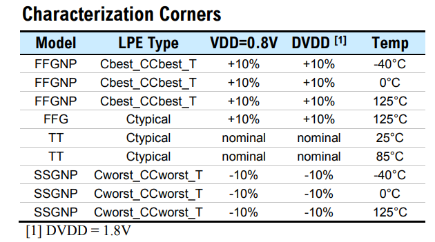
Below table is caputre of Aragio's TSMC16: LVDS datasheet
BEOL corner

Spacing variation is implicitly defined by \(\Delta W_m\).
We denote the conductor width and thickness of the layer m by \(W_m\) and \(T_m\), respectively.
Similarly, we denote the thickness of the layer's interlayer dielectric (i.e., the distance between layer m and layer m +1) by \(H_m\)
- C-based means worst and best caps
- RC-based means worst and best R in adjustment with C (RC product)
Based on experience, it was found that C-based extraction provides worst and best case over RC for internal timing paths because Capacitance dominates short wire.
However, for large design, inter-block timing paths were often worst with RC worst parasitic since R dominates for long wires.
signoff corners for setup & hold

reference
Process Variation
Eric J.-W. Fang, T5: Fundamentals of Process Monitors for Signoff-Oriented Circuit Design, 2022 IEEE International Solid-State Circuits Conference
Alvin Loke, Device and Physical Design Considerations for Circuits in FinFET Technology, ISSCC 2020 Short Course
簡報 Cln16ffcll Sr V1d0 2p1 Usage Guide URL: https://usermanual.wiki/Document/cln16ffcllsrv1d02p1usageguide.1649731847/view
Radojcic, Riko, Dan Perry and Mark Nakamoto. “Design for manufacturability for fabless manufactuers.” IEEE Solid-State Circuits Magazine 1 (2009): n. pag.
How To Reduce Implementation Headaches In FinFET Processes URL: https://semiengineering.com/how-to-reduce-implementation-headaches-in-finfet-processes/
陌上风骑驴看IC, STA | SSGNP, FFGNP. https://mp.weixin.qq.com/s/eJ8fYRJBR1E9XbfH95OUOg
陌上风骑驴看IC, STA | ssg 跟ss corner 的区别——谬误更正版 https://mp.weixin.qq.com/s?__biz=MzUzODczODg2NQ==&mid=2247486225&idx=1&sn=e9c68f6108ae6c9958d47ca0b29373ca&chksm=fad262cfcda5ebd949cc91353c7cbfaf4ba61179306f7d8e98461a4f4ca9d8a9baef5e9f2cc1&scene=178&cur_album_id=1326356275000705025#rd
The Evolution, Pitfalls, and Cargo Cult Engineering of Advanced Digital Timing Sign-off https://www.tauworkshop.com/2021/speaker_slides/christian_l.pdf
Don O'Riordan Cadence Design Systems. Recommended Spectre Monte Carlo modeling methodology [https://designers-guide.org/modeling/montecarlo.pdf]
RC corner
Modeling Sub-90nm On-Chip Variation Using Monte Carlo Method for DFM https://www.aspdac.com/aspdac2007/pdf/archive/2D-1.pdf
Double Patterning for IC Design, Extraction and Signoff https://semiwiki.com/eda/synopsys/1974-double-patterning-for-ic-design-extraction-and-signoff/
抽刀断水水更流,RC Corner不再愁:STA之RC Corner URL: http://mp.weixin.qq.com/s?__biz=MzUzODczODg2NQ==&mid=2247484115&idx=1&sn=de99f27aadf58ea316c284dad9000b7c&chksm=fad26b0dcda5e21b8c9750f738b55053f695843a66c3c202ff0ba586c738f45aa270254c3722&scene=21#wechat_redirect
一曲新词酒一杯,RC Corner继续飞: STA之RC Corner拾遗 URL:https://mp.weixin.qq.com/s?__biz=MzUzODczODg2NQ==&mid=2247484135&idx=2&sn=bddc632850bd10c32b5688fd7af46218&chksm=fad26b39cda5e22f1c3970f8c8c2e1287c9492c526c4caf02b61f61faffdf829381c392d6ea1&scene=21#wechat_redirect
且将新火试新茶,深究趁年华:STA之RC Corner再论 URL:https://mp.weixin.qq.com/s?__biz=MzUzODczODg2NQ==&mid=2247484144&idx=1&sn=059843381e77cd4008d25166db388d02&chksm=fad26b2ecda5e23816b33b3a949f34d4ca09118bad76f1089dfcb228b7da6491f423a5f4e703&cur_album_id=1326356275000705025&scene=189#wechat_redirect
LDP_IN_800_25V_DN: 1.2GHz LVDS Receiver http://aragiosolutions.com/pdf/rgo_tsmc16_18v25_lvds_product_brief_rev_1a.pdf
Parasitic extraction technologies Advanced node and 3D-IC design https://static.sw.cdn.siemens.com/siemens-disw-assets/public/81845/en-US/Siemens-SW-Parasitic-extraction-technologies-for-advanced-WP-81845-C2.pdf
New Game, New Goal Posts: A Recent History of Timing Closure https://pdfs.semanticscholar.org/9360/5ce48f9bd3b7527ae8979f41a9c7e310efa4.pdf
The Evolution, Pitfalls, and Cargo Cult Engineering of Advanced Digital Timing Sign-off https://www.tauworkshop.com/2021/speaker_slides/christian_l.pdf
T. -B. Chan, S. Dobre and A. B. Kahng, "Improved signoff methodology with tightened BEOL corners," 2014 IEEE 32nd International Conference on Computer Design (ICCD), Seoul, Korea (South), 2014, pp. 311-316, doi: 10.1109/ICCD.2014.6974699.
Chan, T. (2014). Mitigation of Variability and Reliability Margins in IC Implementation /. UC San Diego. ProQuest ID: Chan_ucsd_0033D_14269. Merritt ID: ark:/20775/bb52916761. Retrieved from https://escholarship.org/uc/item/35r1m001
Dr. Adam Temanm, Digital VLSI Design:Lecture 10: Routing https://www.eng.biu.ac.il/temanad/files/2017/02/Lecture-10-Routing.pdf
Article (20487193) Title: Setting Pegasus - LVS to Quantus av_extracted view Flow with TSMC16 packages