Parallel Compensation in Two stage amplifier
Parallel Compensation is also known as Lead Compensation, Pole-Zero Compensation
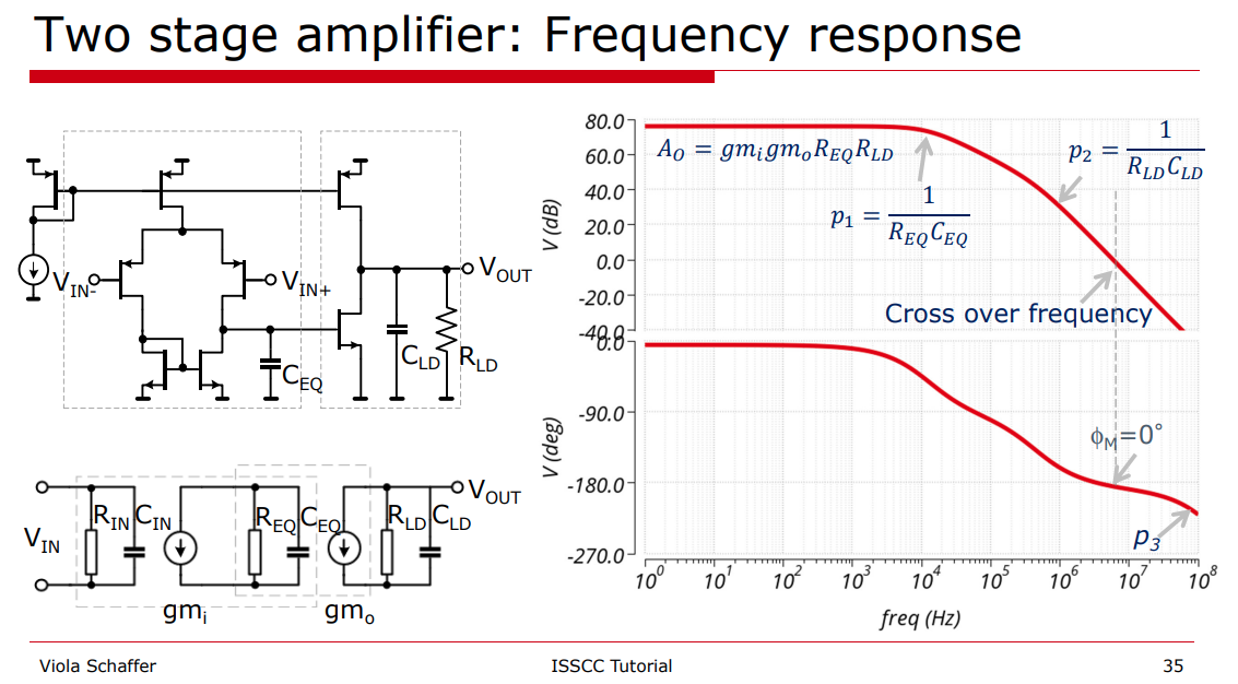
Note: The dominant pole is at output of the first stage, i.e. \(\frac{1}{R_{EQ}C_{EQ}}\).
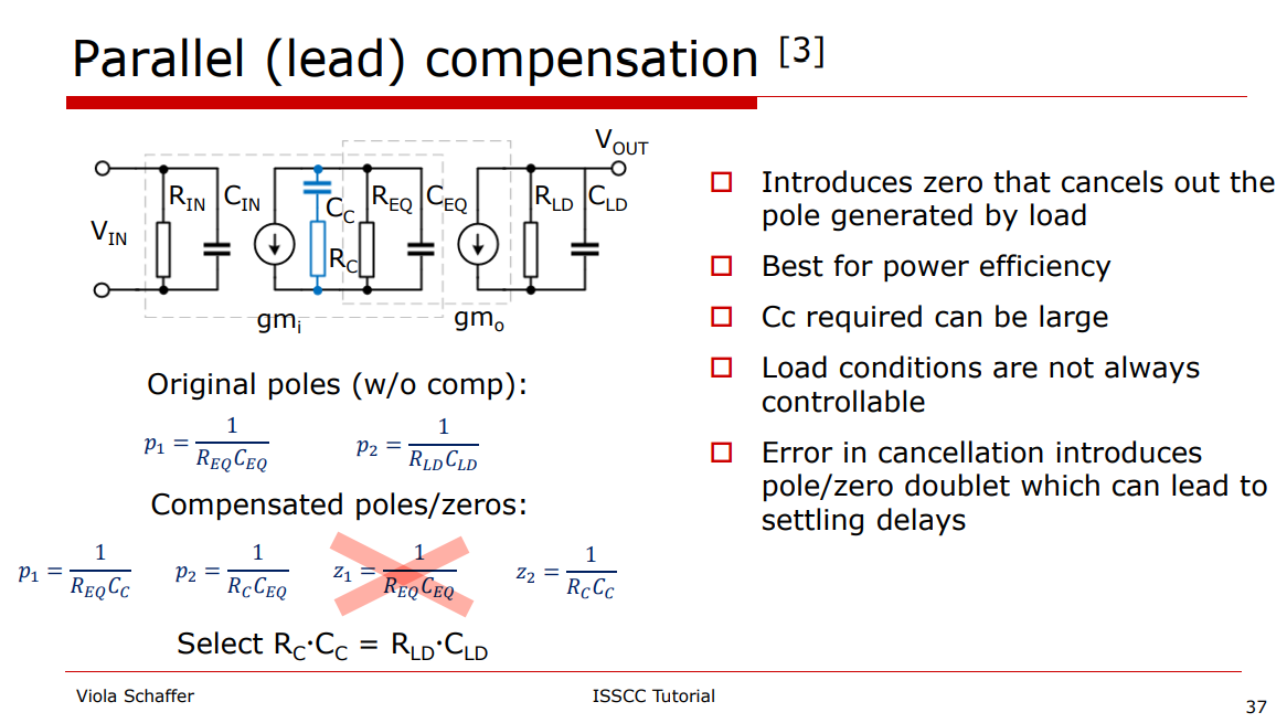
Pole and Zero in transfer function
Design with operational amplifiers and analog integrated circuits / Sergio Franco, San Francisco State University. – Fourth edition
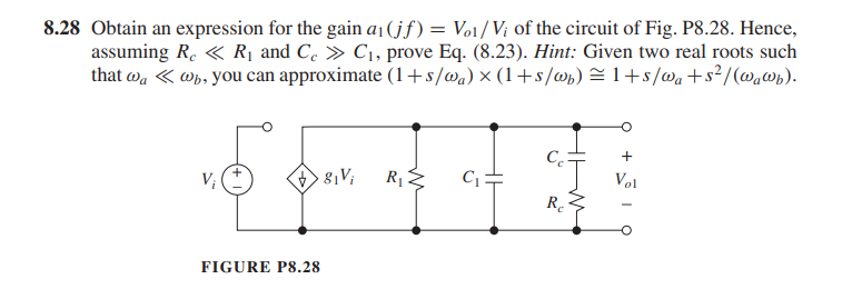
\[ Y = \frac{1}{R_1} + sC_1+\frac{1}{R_c+1/SC_c} \]
\[\begin{align} Z &= \frac{1}{\frac{1}{R_1} + sC_1+\frac{1}{R_c+1/SC_c}} \\ &= \frac{R_1(1+sR_cC_c)}{s^2R_1C_1R_cC_c+s(R_1C_c+R_1C_1+R_cC_c)+1} \end{align}\] If \(p_{1c} \ll p_{3c}\), two real roots can be found \[\begin{align} p_{1c} &= \frac{1}{R_1C_c+R_1C_1+R_cC_c} \\ p_{3c} &= \frac{R_1C_c+R_1C_1+R_cC_c}{R_1C_1R_cC_c} \end{align}\]
The additional zero is \[ z_c = \frac{1}{R_cC_c} \] Given \(R_c \ll R\) and \(C_c \gg C\) \[\begin{align} p_{1c} &\simeq \frac{1}{R_1(C_c+C_1)} \simeq \frac{1}{R_1C_c}\\ p_{3c} &= \frac{1}{R_cC_1}+\frac{1}{R_cC_c}+\frac{1}{R_1C_1} \simeq \frac{1}{R_cC_1} \end{align}\]
The output pole is unchanged, which is \[ p_2 = \frac{1}{R_LC_L} \] We usually cancel \(p_2\) with \(z_c\), i.e. \[ R_cC_c=R_LC_L \]
Phase margin
unity-gain frequency \(\omega_t\) \[ \omega_t = A_\text{DC}\cdot P_{1c} =\frac{g_{m1}g_{m2}R_L}{C_c} \]
PM=45\(^o\) \[ p_{3c} = \omega_t \] Then, \(C_c\) and \(R_c\) can be obtained
\[\begin{align} R_c &= \sqrt{\frac{R_1}{C_1\cdot A_{DC}\cdot p_2}}=\sqrt{\frac{R_1\cdot R_LC_L}{C_1\cdot A_{DC}}} \\ C_c &= \sqrt{\frac{A_{DC}\cdot C_1}{R_1\cdot p_2}}=\sqrt{\frac{A_{DC}\cdot C_1 \cdot R_LC_L}{R_1}} \end{align}\]
PM=60\(^o\) \[ p_{3c} = 2\cdot\omega_t \] Then, \(C_c\) and \(R_c\) can be obtained \[\begin{align} R_c &= \sqrt{\frac{R_1}{C_1\cdot 2A_{DC}\cdot p_2}} = \sqrt{\frac{R_1\cdot R_LC_L}{C_1\cdot 2A_{DC}}} \\ &= \sqrt{\frac{C_L}{2g_{m1}g_{m2}C_1}}\\ C_c &= \sqrt{\frac{2A_{DC}\cdot C_1}{R_1\cdot p_2}} = \sqrt{\frac{2A_{DC}\cdot C_1 \cdot R_LC_L}{R_1}} \\ &= R_L\sqrt{2g_{m1}g_{m2}C_1C_L} \end{align}\]
for the unity-gain frequency \(\omega_t\) we find \[ \omega_t = \sqrt{\frac{1}{2}\cdot \frac{g_{m1}g_{m2}}{C_1C_L}} \] The parallel compensation shows a remarkably good result. The new 0 dB frequency lies only a factor \(\sqrt{2}\) lower than the theoretical maximum
To increase \(\phi_m\), we need to raise \(C_c\) a bit while lowering \(R_c\) in proportion in order to maintain pole-zero cancellation. This causes \(p_{1c}\) and \(p_{3c}\) to split a bit further apart.
1 | clc; |
reference
Viola Schäffer, Designing Amplifiers for Stability, ISSCC 2021 Tutorials
R.Eschauzier "Wide Bandwidth Low Power Operational Amplifiers", Delft University Press, 1994.
Gene F. Franklin, J. David Powell, and Abbas Emami-Naeini. 2018. Feedback Control of Dynamic Systems (8th Edition) (8th. ed.). Pearson. 6.7 Compensation
Application Note AN-1286 Compensation for the LM3478 Boost Controller
ECEN 607 Advanced Analog Circuit Design Techniques Spring 2017 URL: Lect 1D Op-Amps Stability and Frequency Compensation Techniques
Sergio Franco, San Francisco State University, Design with Operational Amplifiers and Analog Integrated Circuits, 4/e
J. H. Huijsing, 6.2.2.1 Two-GA-stage Parallel Compensation (PC), "Operational Amplifiers, Theory and Design, 3rd ed. New York: Springer, 2017"