High Frequency Passive Devices
Matching network
TODO 📅
Q factor
TODO 📅
Self-Resonant Frequency

\[ f_\text{SRF} = \frac{1}{2\pi \sqrt{LC}} \] The SRF of an inductor is the frequency at which the parasitic capacitance of the inductor resonates with the ideal inductance of the inductor, resulting in an extremely high impedance. The inductance only acts like an inductor below its SRF
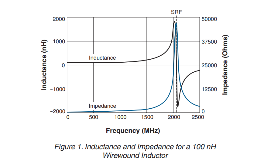
For choking applications, chose an inductor whose SRF is at or near the frequency to be attenuated
For other applications, the SRF should be at least 10 times higher than the operating frequency
it is more important to have a relatively flat inductance curve (constant inductance vs. frequency) near the required frequency
[Understanding RF Inductor Specifications, https://www.ece.uprm.edu/~rafaelr/inel5325/SupportDocuments/doc671_Selecting_RF_Inductors.pdf]
[RFIC-GPT Wiki, https://wiki.icprophet.net/]
T-coil
- Broaden the bandwidth
- Create a constant, resistive input impedance in the presence of a heavy load capacitance (ESD protection circuit)
L1 = L2 for impedance matching
The use of T-coils can dramatically increase the bandwidth and improve the return loss in both TXs and RXs.
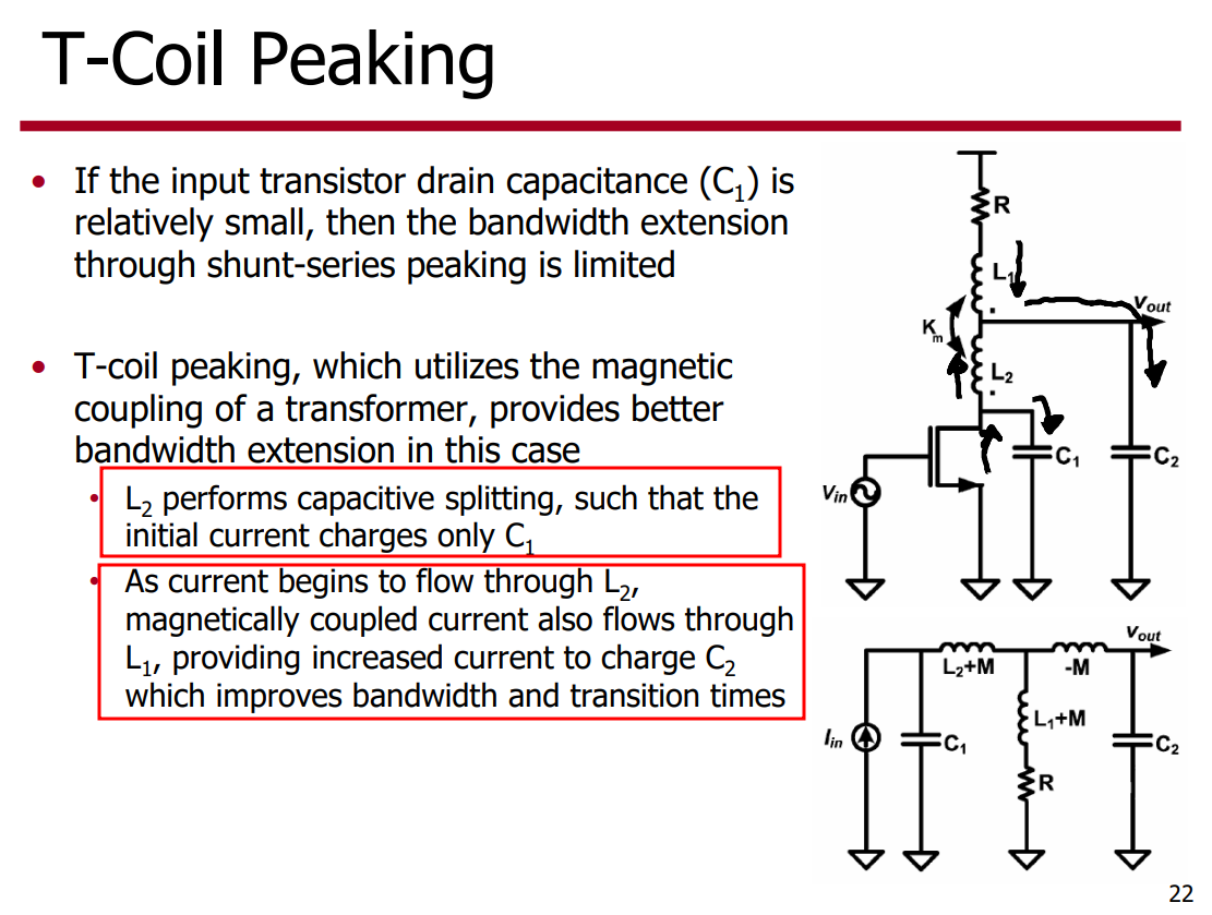
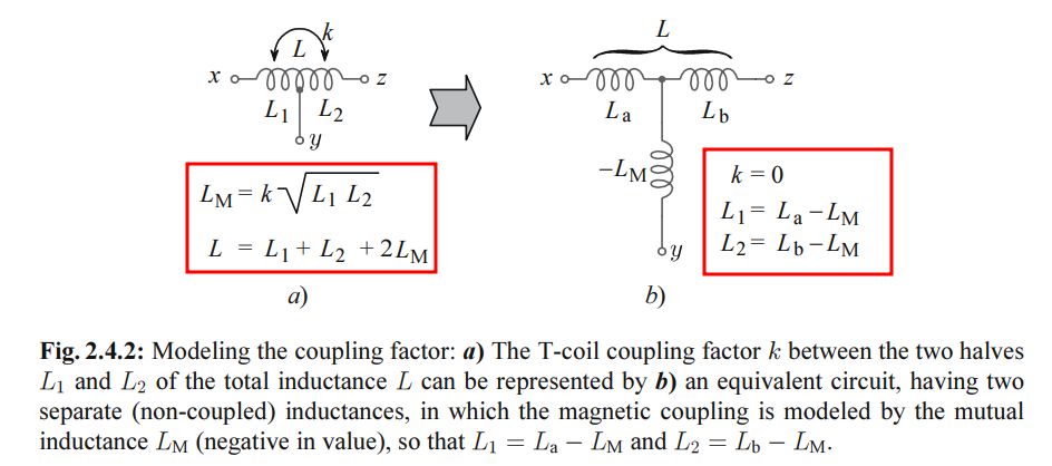
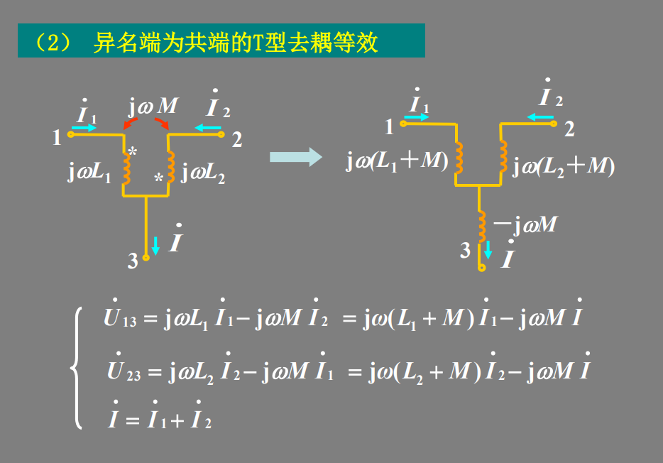
equivalent circuit
Note the negative sign of \(L_M\), which is a consequence of magnetic coupling; owing to this, the driving impedance at the center tap as seen by \(C\) is lower than without the coupling.
\[\begin{align} Z_{c} &= sL_a/2 -sL_M = sL/2 - sL_M/2 \\ Z_{noc} &= sL/2 \end{align}\]
Bridged T-Coil
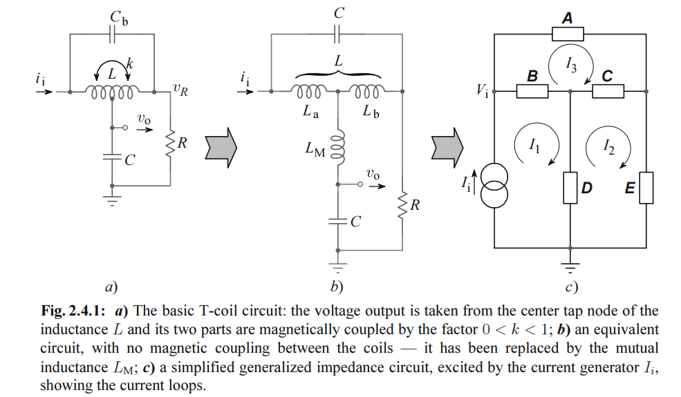
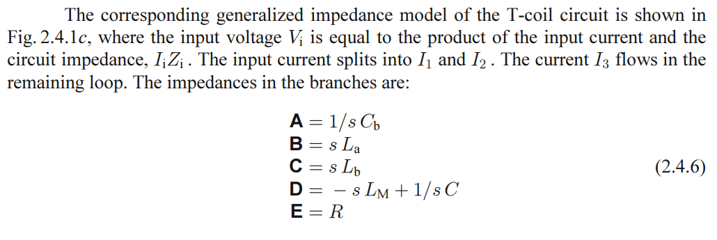
The vertical stacking of the inductor halves causes a significant bridging capacitance \(C_B\) between them.
The most important aspect is that \(C_B\) does not prohibit perfect impedance matching but can be used to tune certain transfer functions.
Tcoil in RX
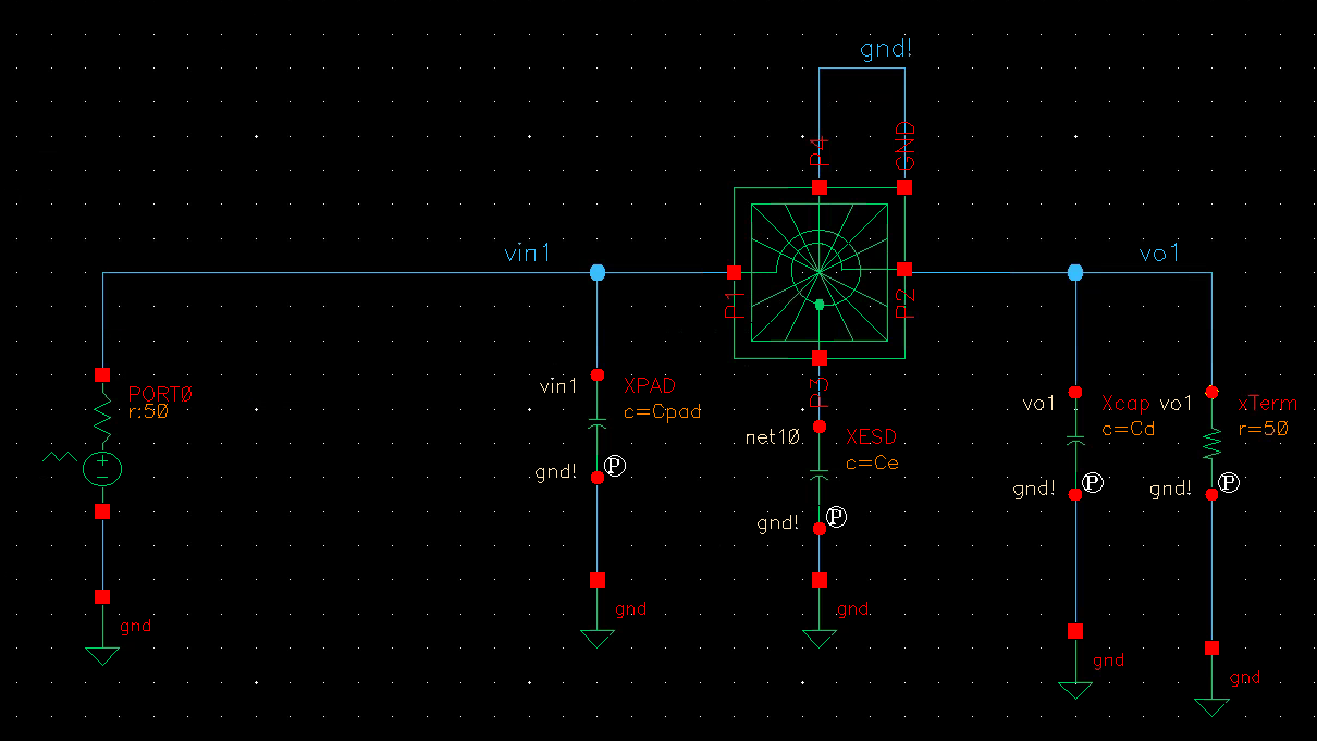
ppwl: Independent Piece-Wise Linear Resistive Source
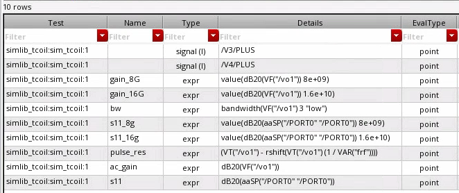
simple model
L1, L2, Km, Cb
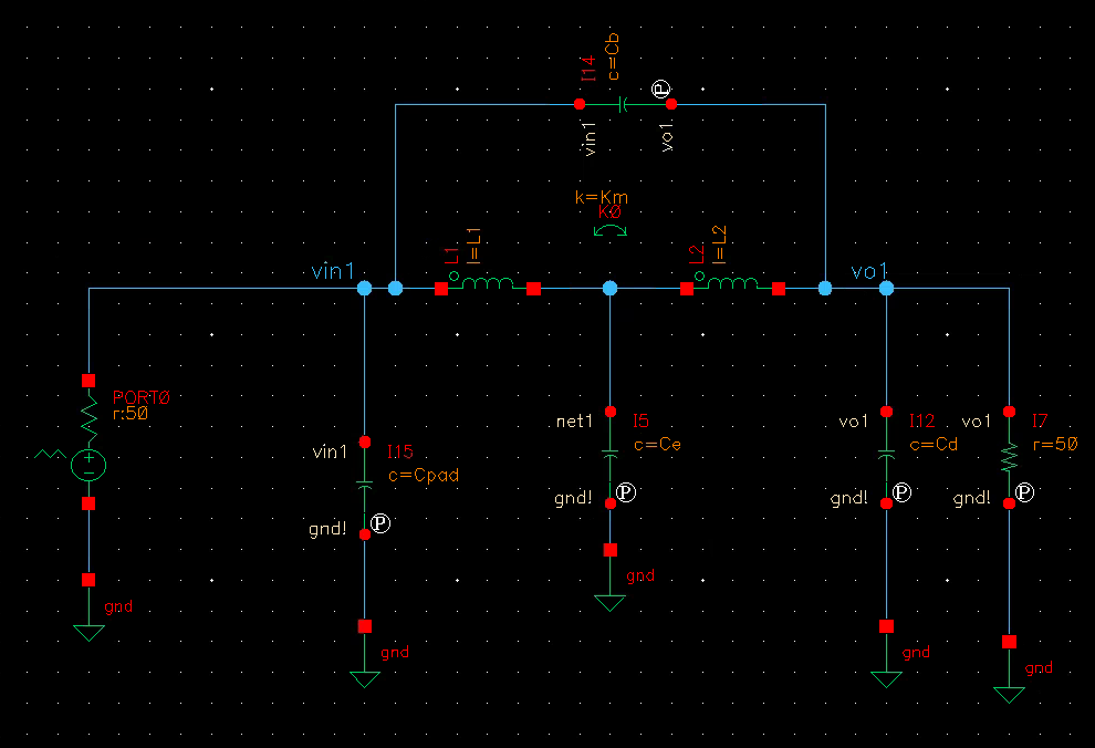
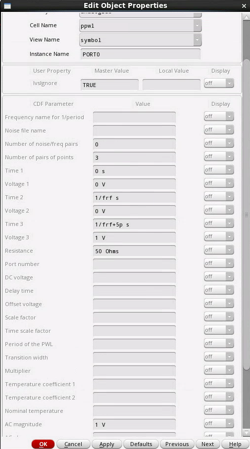
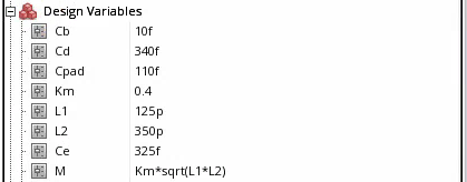
lumped model
1 | simulator lang=spectre |
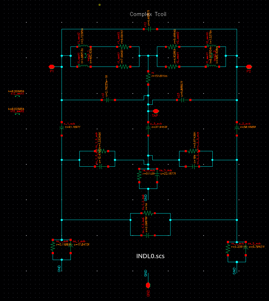
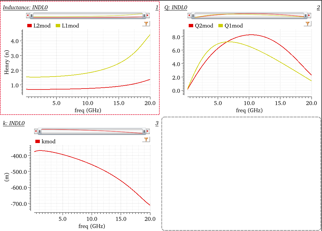
EMX_plot_tcoil in
emxform.ils
1 | (define (EMX_plot_tcoil bgui wid what) |
Tcoil vs tapped inductor
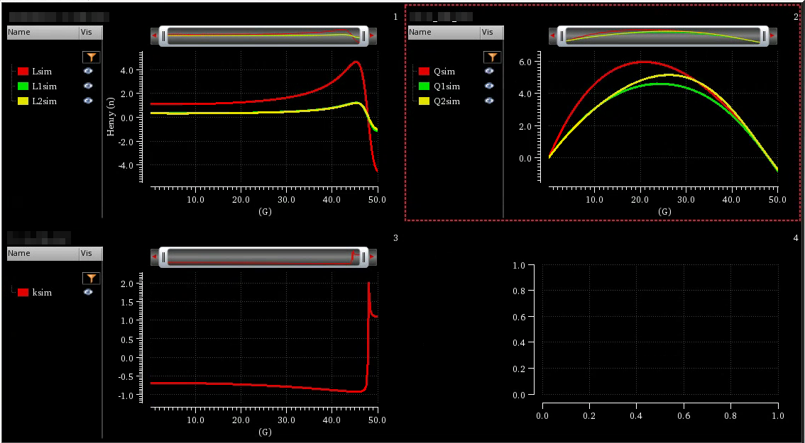
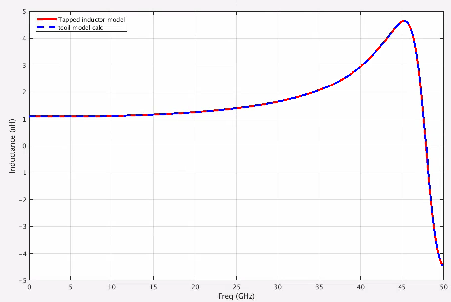
tcoil and tapped inductor share same EM simulation result, and use modelgen with different model formula.
The relationship is \[ L_{\text{sim}} = L1_{\text{sim}}+L2_{\text{sim}}+2\times k_{\text{sim}} \times \sqrt{L1_{\text{sim}}\cdot L2_{\text{sim}}} \] where \(L1_{\text{sim}}\), \(L2_{\text{sim}}\) and \(k_{\text{sim}}\) come from tcoil model result, \(L_{\text{sim}}\) comes from tapped inductor model result
\(k_{\text{sim}}\) in EMX have assumption, induce current from P1 and P2 Given Dot Convention:
Same direction : k > 0
Opposite direction : k < 0
So, the \(k_{\text{sim}}\) is negative if routing coil in same direction
1 | % EMX - shield tcoil model |
电磁感应定律 (electromagnetic induction)
任何封闭电路中感应电动势大小,等于穿过这一电路磁通量的变化率。 \[ \epsilon = -\frac{d\Phi_B}{dt} \] 其中 \(\epsilon\)是电动势,单位为伏特
\(\Phi_B\)是通过电路的磁通量,单位为韦伯
电动势的方向(公式中的负号)由楞次定律决定
楞次定律: 由于磁通量的改变而产生的感应电流,其方向为抗拒磁通量改变的方向。
在回路中产生感应电动势的原因是由于通过回路平面的磁通量的变化,而不是磁通量本身,即使通过回路的磁通量很大,但只要它不随时间变化,回路中依然不会产生感应电动势。
自感电动势
当电流\(I\)随时间变化时,在线圈中产生的自感电动势为 \[ \epsilon = -L\frac{dI}{dt} \]
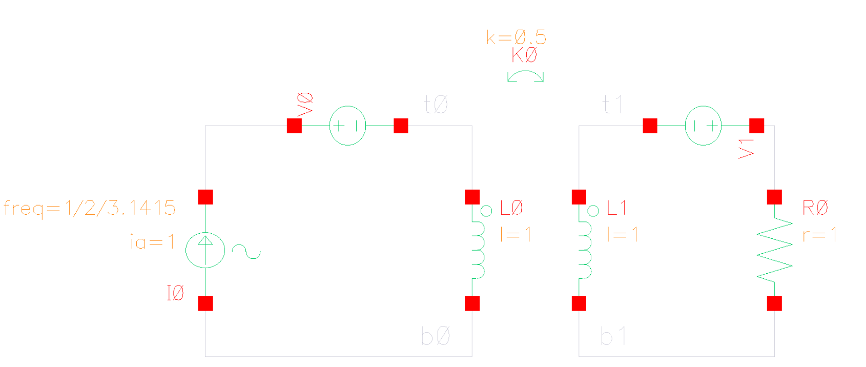
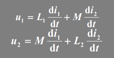
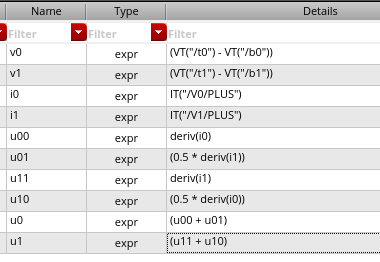
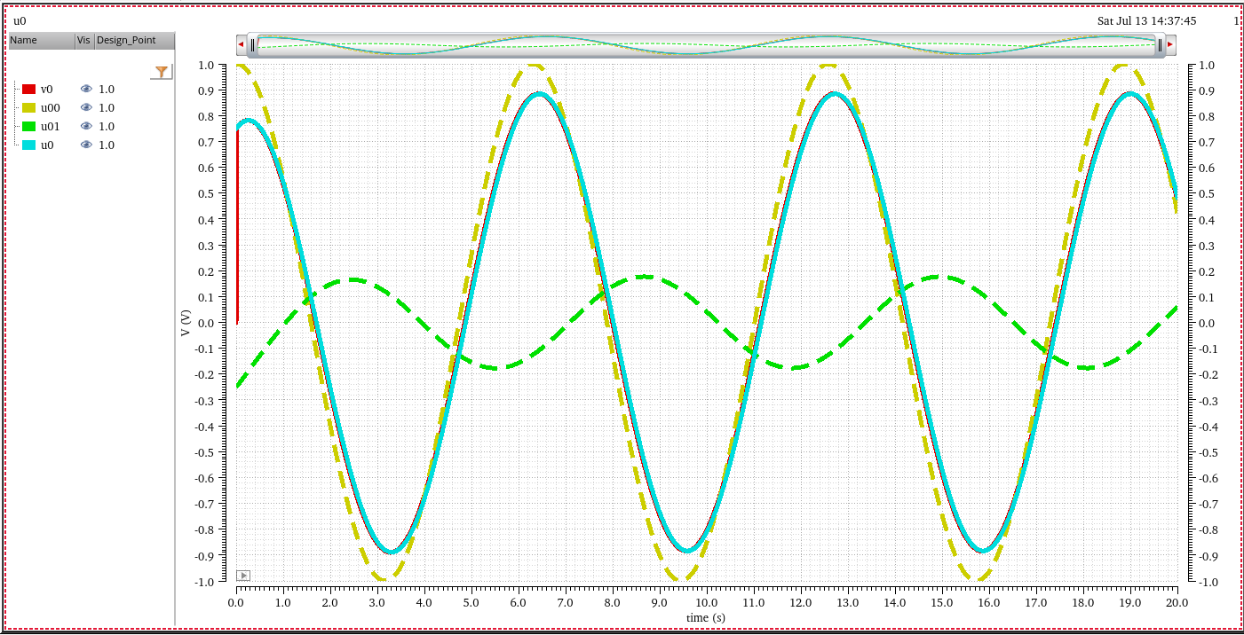
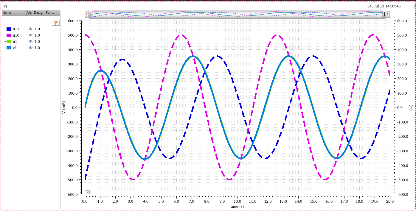
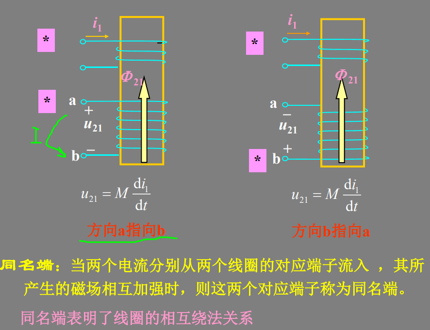
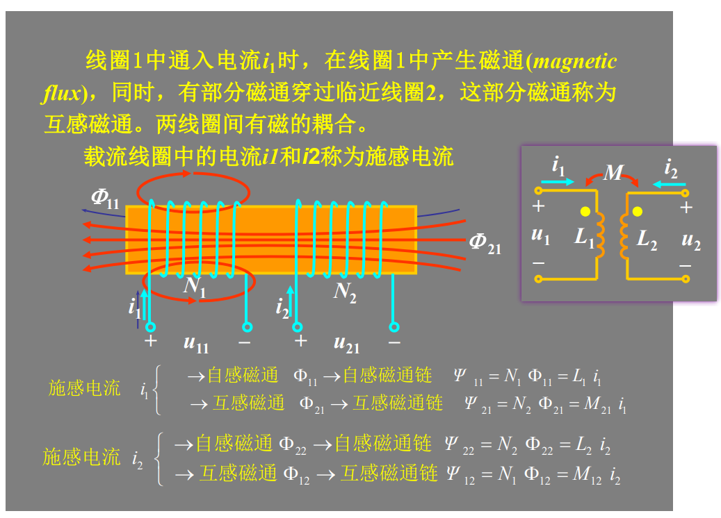
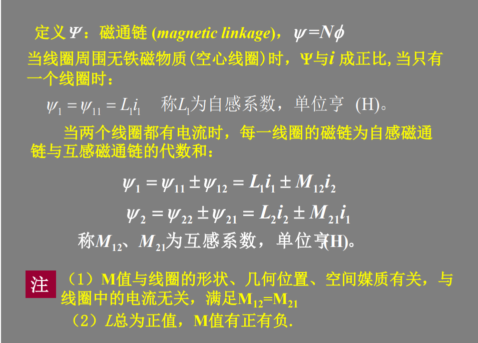
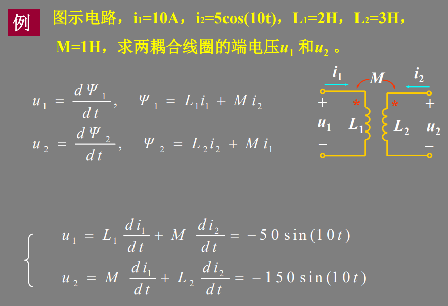
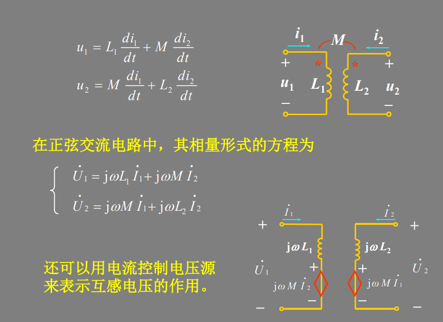
同名端:当两个电流分别从两个线圈的对应端子流入 ,其所 产生的磁场相互加强时,则这两个对应端子称为同名端。
reference
S. Shekhar, J. S. Walling and D. J. Allstot, "Bandwidth Extension Techniques for CMOS Amplifiers," in IEEE Journal of Solid-State Circuits, vol. 41, no. 11, pp. 2424-2439, Nov. 2006
David J. Allstot Bandwidth Extension Techniques for CMOS Amplifiers
B. Razavi, "The Bridged T-Coil [A Circuit for All Seasons]," IEEE Solid-State Circuits Magazine, Volume. 7, Issue. 40, pp. 10-13, Fall 2015.
B. Razavi, "The Design of Broadband I/O Circuits [The Analog Mind]," IEEE Solid-State Circuits Magazine, Volume. 13, Issue. 2, pp. 6-15, Spring 2021.
S. Galal and B. Razavi, "Broadband ESD protection circuits in CMOS technology," in IEEE Journal of Solid-State Circuits, vol. 38, no. 12, pp. 2334-2340, Dec. 2003, doi: 10.1109/JSSC.2003.818568.
M. Ker and Y. Hsiao, "On-Chip ESD Protection Strategies for RF Circuits in CMOS Technology," 2006 8th International Conference on Solid-State and Integrated Circuit Technology Proceedings, 2006, pp. 1680-1683, doi: 10.1109/ICSICT.2006.306371.
M. Ker, C. Lin and Y. Hsiao, "Overview on ESD Protection Designs of Low-Parasitic Capacitance for RF ICs in CMOS Technologies," in IEEE Transactions on Device and Materials Reliability, vol. 11, no. 2, pp. 207-218, June 2011, doi: 10.1109/TDMR.2011.2106129.
Bob Ross, "T-Coil Topics" DesignCon IBIS Summit 2011
Ross, Bob and Cong Ling. “Wang Algebra: From Theory to Practice.” IEEE Open Journal of Circuits and Systems 3 (2022): 274-285.
S. Lin, D. Huang and S. Wong, "Pi Coil: A New Element for Bandwidth Extension," in IEEE Transactions on Circuits and Systems II: Express Briefs, vol. 56, no. 6, pp. 454-458, June 2009
Starič, Peter and Erik Margan. “Wideband amplifiers.” (2006).
Kosnac, Stefan (2021) Analysis of On-Chip Inductors and Arithmetic Circuits in the Context of High Performance Computing [https://archiv.ub.uni-heidelberg.de/volltextserver/30559/1/Dissertation_Stefan_Kosnac.pdf]
Chapter 4.5. High Frequency Passive Devices [https://www.cambridge.org/il/files/7713/6698/2369/HFIC_chapter_4_passives.pdf]
