How to Save Node in DSPF?
DSPF Semantics
*|DIVIDER <divider>
<divider> represents the hierarchical pathname
divider. The default hierarchical character is forward slash
(/).
*|DELIMITER <delimiter>
<delimiter>represents the delimiter character used to concatenate an instance name and pin name to form an instance pin name.- It is also represents the delimiter character used to concatenate a net name and subnode number to form a subnode name. The default character is colon (:)
*|BUSBIT <left_busbit_char><right_busbit_char>
<left_busbit_char> and
<right_busbit_char> are used at the end of an
identifier of an array to select a single object of the array.
Objects which may be indexed include nets, primary pins, and instance pins
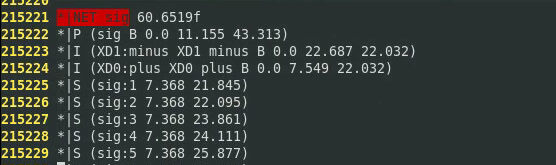
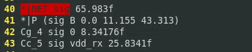
*|NET <netName> <netCap>
<netName>represents the name of a net. It can be a user-provided net name, the name of the driving pin, or the name of the driving instance pin.<netCap>represents the total capacitance value in farads associated with the net. This may be comprised of capacitances to ground and capacitances to nearby wires.
*|P <pinName> <pinType> <pinCap> {<coord>}
<pinName>represents the name of the pin.<pinType>represents the type of the pin. It can be any of the following: I (Input), O (Output), B (Bidirectional), X (don’t care), S (Switch), and J (Jumper).<pinCap>represents the capacitance value associated with the pin.<coord>is optional. It represents the location of the pin. Multiple pin locations are allowed.
*|S <subNodeName> {<coord>}
subnodes in the net
<subNodeName>represents the name of the subnode. A subnode name is obtained by concatenating the net name and a subnode number using the delimiter specified in the DELIMITER statement. The default delimiter is colon (:).<coord>represents the location of the subnode.
*|I <instPinName> <instName> <pinName> <pinType><pinCap> {<coord>?}
describes instance pins in the net
<instPinName>represents the name of the instance pin. An instance pin name is obtained by concatenating the<instName>and the<pinName>with a delimiting character which is specified by the DELIMITER statement<instName>represents the name of the instance
*|DeviceFingerDelim "@"
MOS finger delimiter
For example, M8's finger is 4, then split into 4 Devices
in DSPF
MM8,MM8@2,MM8@3,MM8@4
its drain terminal will be
MM8:d,MM8@2:d,MM8@3:d,MM8@4:d
DSPF Syntax
DSPF has two sections:
a net section
The net section consists of a series of net description blocks. Each net description block corresponds to a net in the physical design. A net description block begins with a net statement followed by pins, instance pins, subnodes, and parasitic resistor/capacitor (
R/C) components that characterize the electrical behavior of the net.an instance section
The instance section consists of a series of SPICE instance statements. SPICE instance statements begin with an
X.
Each file consists of hierarchical cells and interconnects only.
The DSPF format is as generic and as much like SPICE as possible. While native SPICE statements describe the R/C sections, some non-native SPICE statements complete the net descriptions. These non-native SPICE statements start with the notation "*|" to differentiate them from native SPICE statements. For native SPICE statements, a continuation line begins with the conventional "+" sign in the first column.
The native SPICE statements used by the DSPF format are listed below:
.SUBCKTrepresents a subcircuit statement..ENDSrepresents the end of a subcircuit statement.Rrepresents a resistor element.Crepresents a capacitor element.Erepresents a voltage-controlled voltage sources element.Xrepresents an instance of a cell;*represents a comment line unless it is*|or*+..ENDis an optional statement that represents the end of a simulation session
spectre netlist
hier_delimiter="."
Used to set hierarchical delimiter. Length of
hier_delimiter should not be longer than 1, except the
leader escape character
spfbusdelim = busdelim_schematic [busdelim_parasitic]
This option maps the bus delimiter between schematic netlist and parasitic file (i.e. DSPF, SPEF, or DPF). The option defines the bus delimiter in the schematic netlist, and optionally the bus delimiter in the parasitic file. By default, the bus delimiter of the parasitic file is taken from the parasitic file header (i.e. |BUSBIT [], |BUS_BIT [], or *|BUS_DELIMITER []). If the bus delimiter is not defined in the parasitic file header, you need to specify it by using the spfbusdelim option in schematic netlist.
Exampel
- spfbusdelim=<> - A<1> in the schematic netlist is mapped to A_1 in the DSPF file, if the bus delimiter header in the DSPF file is "_".
- spfbusdelim=@ [] - A@1 in the schematic netlist is mapped to to A[1] in the DSPF file (the bus delimiter in DSPF header will be ignored).
How to Save Net voltage in DSPF
!!! follow the name of net section in DSPF - prepend to top-level devices in the schematic with
X

Assume node n1...n4 are named as below in DSPF file (prefix
X)
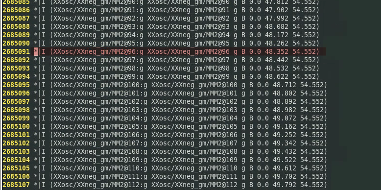
n1
XXosc/zip:1
n2
XXosc/zip:2
n3
XXosc/zip:3
n4
XXosc/zip:4
To save these nodes, you can add follow code in Definition Files
saveopt.scs
1 | save Xwrapper.Xvco.XXosc\/zip\:1 |
Escape character
\is used for hierarchical pathname divider/and subnode:By the way,
.is hierarchical delimiter of SpectreCalibre always prepend one X to instance name of schematic in generated DSPF file
The DSPF design is flatten, the DIVIDER character indicate the hierarchy
1 | save Xwrapper.Xvco.XXosc\/zip |
The above save voltage, however I'm NOT sure which node it save.
To avoid this unsure problem, the MOS terminal may be better choice to save.
But keep in mind
- OD resistance is lumped in the FEOL model
- M0OD and above layer resistances are extracted by RC tool
How to Save Current in DSPF
!!! follow the name of instance section of DSPF - prepend to top-level devices in the schematic with
XX
MOS in schematic: Xsupply.M4
MOS related information in DSPF (prefix XX in instance
section):
1 | ... |
To save drain current:
1 | save Xvco.XXXsupply\/MM4:d |
<instName>in*|I <instPinName> <instName> <pinName> <pinType><pinCap> {<coord>?}which has prefixXcorresponding to schematic is NOT the instance name in DSPF. The instance name is in instance section and has prefixXX

!!! Only work for MOS terminal current. Fail to apply to block pin
Thinking about voltage and current save
- MOS device always prepend with
M - To save net voltage, take account of the prefix
Xof top-level device - To save MOS terminal, take account of the prefix
XXof top-level device
Post-layout netlists are created by layout extraction tools - Mentor Calibre
Differences Between DSPF and Schematic Names
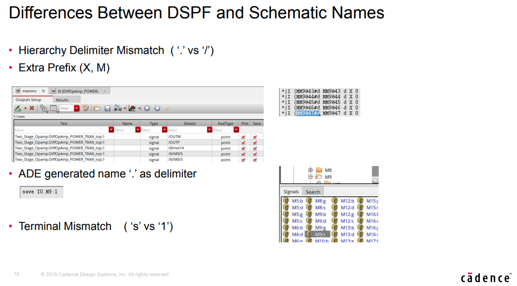
- MOS Terminal Mismatch ( ‘s’ vs ‘1’)
- Schematic: number '1' ,'2', '3','4'
- DSPF: 'd', 'g', 's','b'
.simrc file
If DSPF files show such differences, you can set options in the .simrc file to update the save statement in the netlist so that the device names match with those in the DSPF file
Additionally, dspf_include reads all the DSPF lines
starting with * (|NET, |I, *|P,*|S), while
include considers all related lines as comments.
Only verified to DSPF output of Mentor Calibre
1 | ; ensure that the netlist is recreated each time |
spfFileDevicePrefixForTermCurrentandspfFileDevicePrefixForOppointsare applicable to MOS devices only.
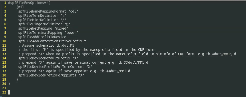
Both
@and__have been observed as Finger Delimiter in single DSPF . wired...
signal name saved using wildcard operator
How to find the signal name saved using wildcard operator with save statement in spectre?
method 1
From ADE L or ADE XL Test Editor, you can use menu Simulation →
Options → Analog→ Miscellaneous → Addition arguments
field:dump_wildcard_info=yes
method 2
add below in netlist file or Simulation Files → Definition
Files:saveopt.scs
saveopt.scs
1 | wcOption options dump_wildcard_info=yes |
saved file
After running simulation, saved wildcard summary is save into file
<netlist_file_name>.wildcard.out*
1 | Wildcard match summary: |
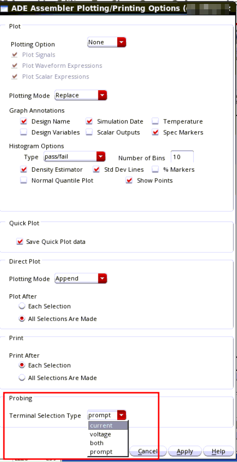
Save and Plot terminal voltage in ADE Explorer and Assembler
.cdsinit
1 | envSetVal("auCore.selection" "terminalSelectionType" 'cyclic "current") |
Available options are current, voltage, both or prompt and the default is current which matches the default behavior in previous releases.
- The schematic will have an ellipse annotation where a current probe has been saved,
- a V annotation for a voltage probe,
- and both annotations for both.
NOTE: Starting with IC 6.1.8 ISR5, you can now set this from Options->Plotting/Printing
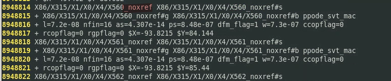
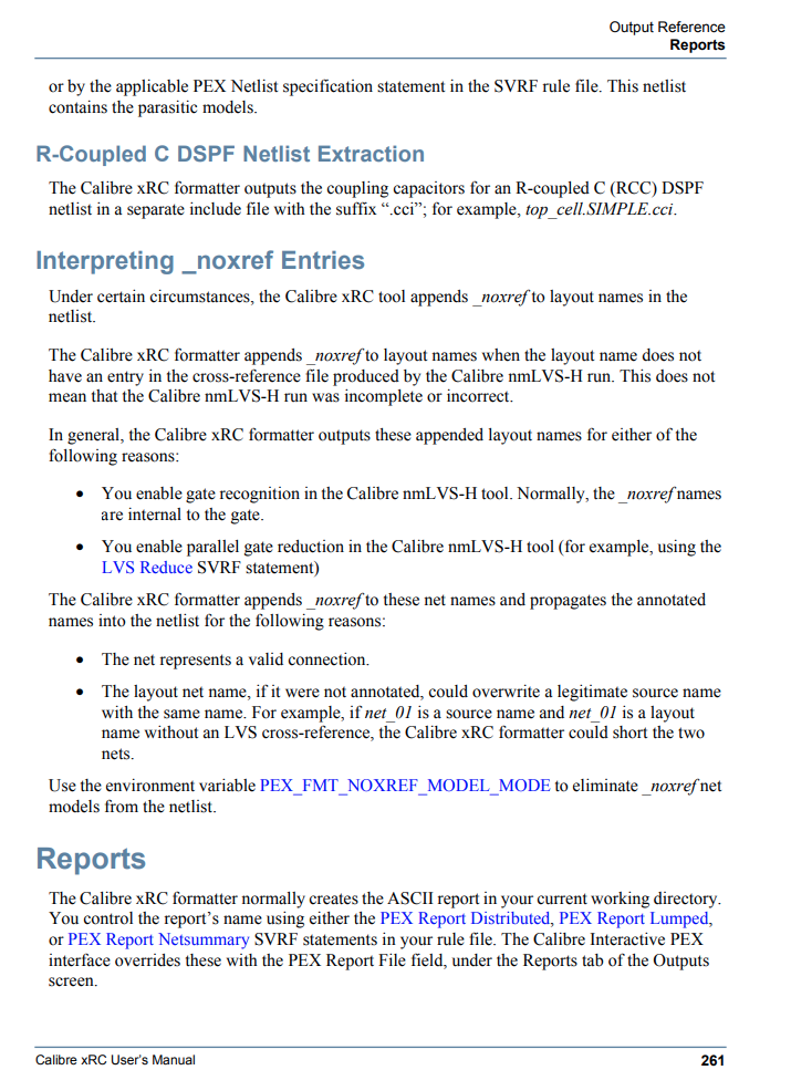
Interpreting _noxref Entries
You enable gate recognition in the Calibre nmLVS-H tool. Normally, the _noxref names are internal to the gate
Saving net with hierarchy delimiter and colon (:) in net name gives WARNING (SPECTRE-8282) during simulation
Problem
I am running simulation using an spf/spef file which has a net name
definition as shown in the below example: 1
2
3
4
5
6
7
8
9
10
11
12
13
14
15
16
17// input.scs
simulator lang=spice
.subckt pi_rc a z
r1 a x1a 1k
r2 x1a x1/x1:DRN 1k
cb x1/x1:DRN z 200f
.ends
xpi1 in 0 pi_rc
vdd in 0 pwl (0 0 1n 0 1.1n 10)
simulator lang=spectre
myopt options hier_ambiguity=lower
tran tran stop=2u
save xpi1.x1\/x1:DRN
The net name is x1/x1:DRN. During the simulation, the following warning is reported:
Warning from spectre during initial setup. 1
2WARNING (SPECTRE-8282): `xpi1.x1/x1' is not a device or subcircuit instance name.
WARNING (SPECTRE-8287): Ignoring invalid item `xpi1.x1/x1:DRN' in save statement.
How can I save this net for plotting and measurements?
Solution
The colon (:) in the save statement specifies terminal current. So, the save statement used above is for terminal current and, hence, the warning messages are reported.
1 | save xpi1.x1\/x1:DRN |
You need to modify the save statement as below: 1
save xpi1.x1\/x1\:DRN
Now, run the simulation and the issue will be resolved.
DSPF r vs rcc
rcc
c
only c dspf give the lumped capacitance