Verilog & SystemVerilog
questasim sim flow
A Short Intro to ModelSim Verilog Simulator [https://users.ece.cmu.edu/~jhoe/doku/doku.php?id=a_short_intro_to_modelsim_verilog_simulator]
1 | vlib work |
-voptargs=+acc: Add the option-voptargs=+accto the vsim command, This enables full visibility into every aspect of the design.
1 | module topmodule; |
uvm:
1 | > vlog test_pkg.sv tb_top.sv -L $QUESTA_HOME/uvm-1.2 |
verilog-mode.el
Emacs Online Documentation https://doc.endlessparentheses.com/
Emacs verilog-mode 的使用 URL: https://www.wenhui.space/docs/02-emacs/verilog_mode_useguide/
1 | emacs --no-site-file --load path/to/verilog-mode.el --batch filename.v -f verilog-auto-save-compile |
CAUTION: filename.v is overwrite by command
verilog-mode.el
1 | /*AUTOINPUT*/ |
-f verilog-batch-auto
For use with
--batch, perform automatic expansions as a stand-alone tool. This sets up the appropriate Verilog mode environment, updates automatics with M-x verilog-auto on all command-line files, and saves the buffers. For proper results, multiple filenames need to be passed on the command line in bottom-up order.
-f verilog-auto-save-compile
Update automatics with M-x verilog-auto, save the buffer, and compile
Emacs
--no-site-file
Another file for site-customization is site-start.el.
Emacs loads this before the user's init file
(.emacs, .emacs.el or
.emacs.d/.emacs.d). You can inhibit the loading of this
file with the option --no-site-file
--batch
The command-line option --batch causes Emacs to run
noninteractively. The idea is that you specify Lisp programs to run;
when they are finished, Emacs should exit.
--load, -l FILE, load Emacs Lisp FILE using the load
function;
--funcall, -f FUNC, call Emacs Lisp function FUNC with
no arguments
-f FUNC
--funcall, -f FUNC, call Emacs Lisp function FUNC with
no arguments
--load, -l FILE
--load, -l FILE, load Emacs Lisp FILE using the load
function
Verilog-mode is a standard part of GNU Emacs as of 22.2.
multiple directories
AUTOINST only search in the file's directory default.
You can append below verilog-library-directories for
multiple directories search
1 | // Local Variables: |
plusargs in Verilog
systemverilog-command-line-input URL: https://www.chipverify.com/systemverilog/systemverilog-command-line-input
PLUSARGS IN SYSTEMVERILOG URL:https://www.theartofverification.com/plusargs-in-systemverilog/
plusargs are command-line switches supported by the
simulator. As per SystemVerilog LRM arguments beginning with the
+ character will be available using the
$test$plusargs and $value$plusargs PLI
APIs.
1 | $test$plusargs (user_string) |
1 | // tb.v |
compile
1
2$ vlib work
$ vlog -sv tb.vsimulate (QuestaSim)
without plusargs
1
$ vsim work.tb -c -do "run; exit"
1
2
3
4
5
6
7
8
9# //
# Loading sv_std.std
# Loading work.tb(fast)
# run
# There is NO $test$plusargs
# There is NO $value$plusargs
# exit
# End time: 13:04:23 on Jun 04,2022, Elapsed time: 0:00:01
# Errors: 0, Warnings: 0with plusargs
1
$ vsim work.tb -c -do "run; exit" +SEED=31 +RUNSIM
+SEED=31 +RUNSIM1
2
3
4
5
6
7
8
9# //
# Loading sv_std.std
# Loading work.tb(fast)
# run
# There is RUNSIM plusargs
# SEED= 31
# exit
# End time: 13:04:55 on Jun 04,2022, Elapsed time: 0:00:01
# Errors: 0, Warnings: 0
Inertial & transport delays
Verilog Nonblocking Assignments With Delays, Myths & Mysteries
Correct Methods For Adding Delays To Verilog Behavioral Models
Article (20488135) Title: Selecting Different Delay Modes in GLS (RAK)
Article (20447759) Title: Gate Level Simulation (GLS): A Quick Guide for Beginners
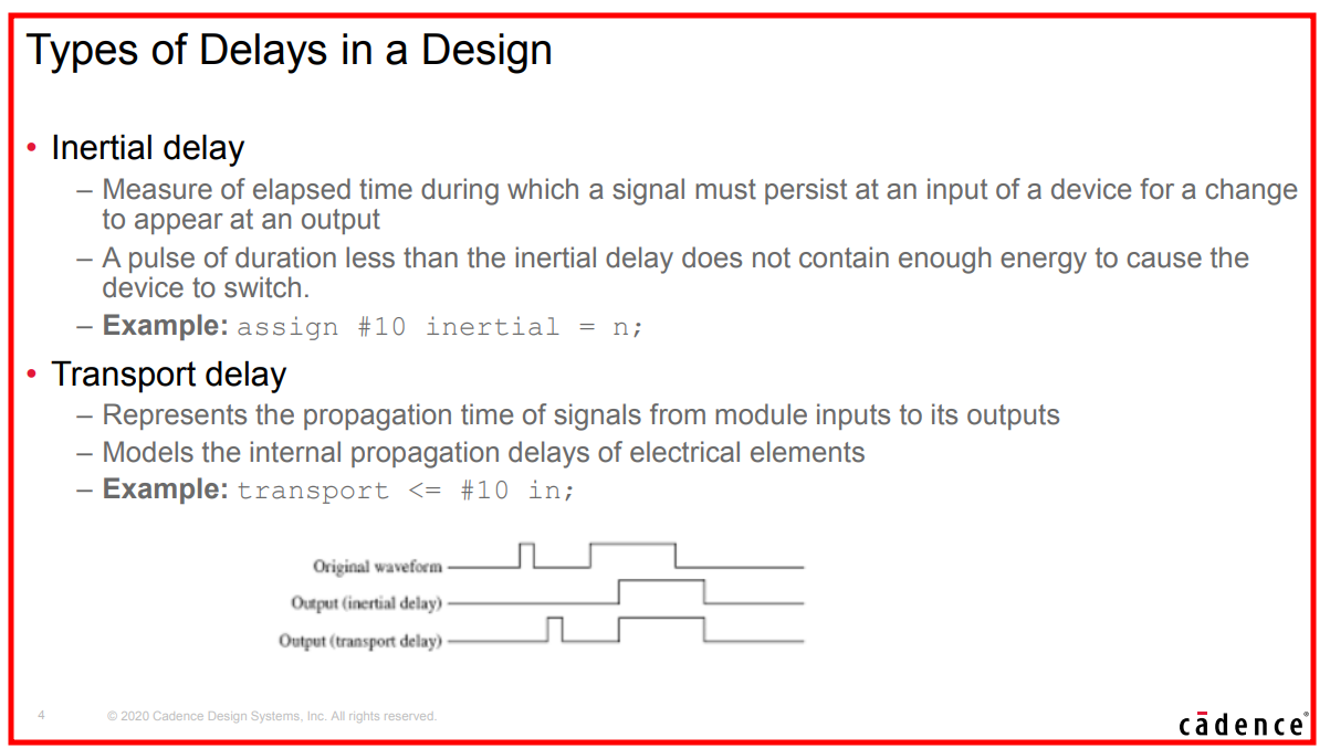
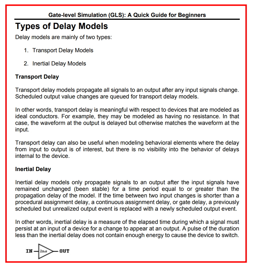
Inertial delay
Inertial delay models are simulation delay models that filter pulses
that are shorted than the propagation delay of Verilog gate
primitives or continuous assignments
(assign #5 y = ~a;)
COMBINATIONAL LOGIC ONLY !!!
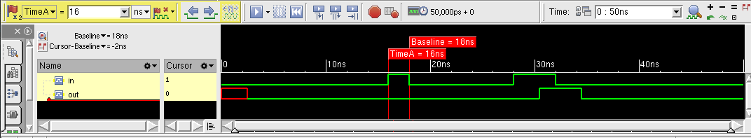
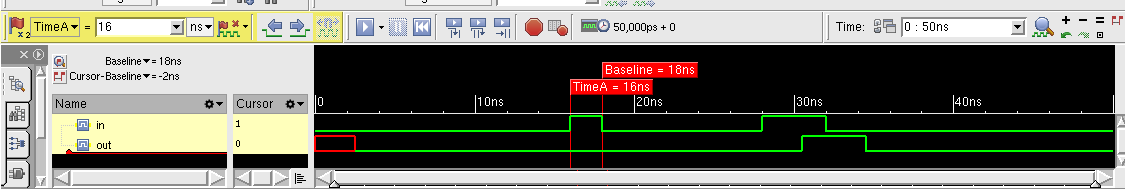
- Inertial delays swallow glitches
- sequential logic implemented with procedure assignments DON'T follow the rule
continuous assignments
1 |
|
procedure assignment - combinational logic
1 |
|
procedure assignment - sequential logic
1 |
|
As shown above, sequential logic DON'T follow inertial delay
Transport delay
Transport delay models are simulation delay models that pass all pulses, including pulses that are shorter than the propagation delay of corresponding Verilog procedural assignments
- Transport delays pass glitches, delayed in time
- Verilog can model RTL transport delays by adding explicit delays to the right-hand-side (RHS) of a nonblocking assignment
1 | always @(*) |
nonblocking assignment
1 |
|
blocking assignment
1 |
|
It seems that new event is discarded before previous event is realized.
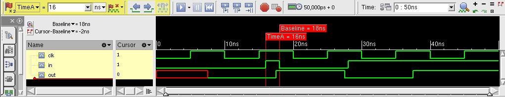
clocking block in SystemVerilog
Assignment at <interface>.<clocking block>.<output signal> (i.e. synchronous) do NOT change <interface>.<output signal> until active clock edge.
1 | // router_io.sv |
All interface signals are asynchronous and without a direction spection (i.e. input, output, inout).
- The direction can only be specified in
clockingblock for synchronous signals- or a
modportfor asynchronous signalsAll directions for the signals in the clocking block must be with respect to the test program;
1 | // test.sv |
1 | // router_test_top.sv |
compile:
1 | $ vcs -sverilog -full64 -kdb -debug_access+all router_test_top.sv test.sv router_io |
file with `
timescalemust be placed in the first, which isrouter_test_top.svin above example
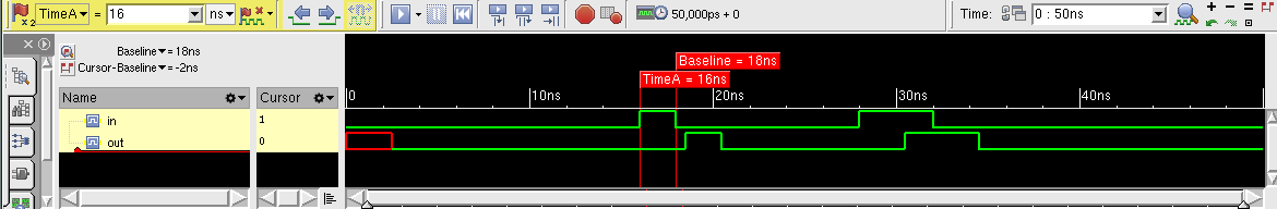
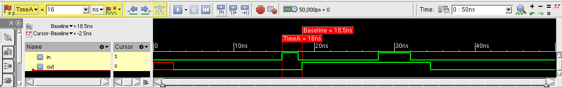
clocking.output
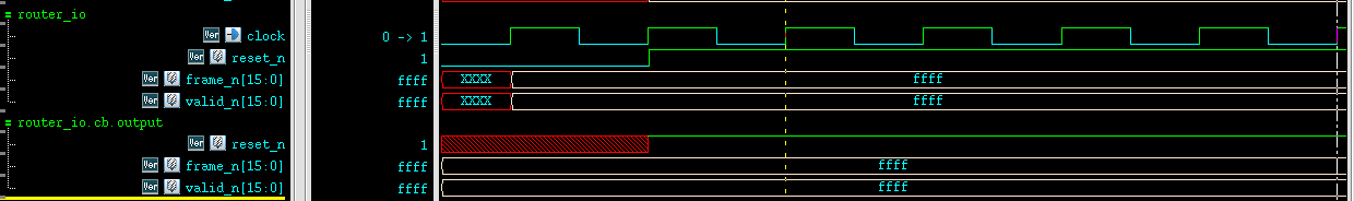
systemverilog don't pass clocking.output to interface's until current or next active edge and after output-skew
clocking.input
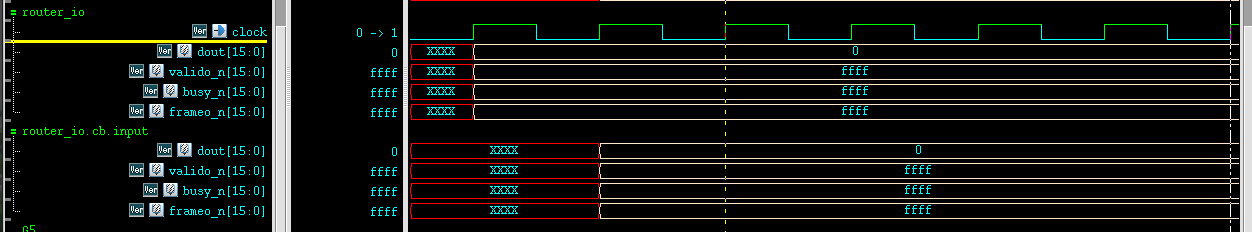
Systemverilog automatically update clocking.input signal from interface's value, input-skew before active edge
Gotcha
An interface must be compiled separately like a
module and CANNOT `include inside a
package or ohter module
Cadence EE_pkg 101
What Is Real Number Modeling?
- model analog blocks operation as signal flow model
- only the digital solver is used for high-speed simulation
- Event-driven
- No convergence issues, because no analog solver is used
- Five different language standards support real number modeling:
- wreal (wired-real) ports in Verilog-AMS
- real data type in VHDL
- real data type in Verilog
- real variables and nettypes in SystemVerilog (SV)
- real types in e
Benefits of RNM
- Most analog circuits that need to be modeled for MS verification at the SoC level can be described in terms of real-valued voltages or currents
- RNM is a mixed approach, borrowing concepts from both continuous and
discrete domains
- The values are floating-point (real) number.
- Time is discrete; the real signals change values based on discrete events
- Applicability of RNM is bounded primarily by signal-flow model style
- Migrating analog behavior from the analog domain to the event or pseudo-analog domain can bring huge benefits without sacrificing too much accuracy
- Simulation is executed by a digital simulation engine without need for the analog solver
- Hence real-number modeling enables very high performance simulation of mixed-signal systems
Limitations of RNM
- connecting real or wreal signals
to electrical signals requires careful consideration
- Too conservative an approach can lead to large numbers of timepoints
- Too liberal an approach can lead to losing signal accuracy
- Time accuracy limited by the discrete sampling approach and the
`
timescalesetting - no continuous signals anymore - Limited capability for combination of signals by wiring outputs
together
- Requires assumptions about impedances to do simple merging
constant part-select and indexed part-select in Verilog
Verilog scalar and vector [link]
What is the "+:" operator called in Verilog? [link]
A range of contiguous bits can be selected and is known as part-select. There are two types of part-selects, one with a constant part-select and another with an indexed part-select
1 | reg [31:0] addr; |
Having a variable part-select allows it to be used effectively in loops to select parts of the vector. Although the starting bit can be varied, the width has to be constant.
[<start_bit +:
] // part-select increments from start-bit [<start_bit -:
] // part-select decrements from start-bit
Example
1 | logic [31: 0] a_vect; |
Mixing Signed and Unsigned in Verilog
Bevan Baas, VLSI Digital Signal Processing, EEC 281 - VLSI Digital Signal Processing [https://www.ece.ucdavis.edu/~bbaas/281/]
Sign Extension
- Calculate the necessary minimum width of the sum so that it contains all input possibilities
- Extend the inputs' sign bits to the width of the answer
- Add as usual
- Ignore bits that ripple to the left of the answer's MSB
- signed
| inA (signed) | inB (signed) | outSum (signed/unsigned) |
|
|---|---|---|---|
| 0101 (5) | 1111 (-1) | ||
| extend sign | 00101 | 11111 | |
| sum result | 00100 |
1 | module tb; |
- mixed
| inA (signed) | inB (unsigned) | outSum (signed/unsigned) |
|
|---|---|---|---|
| 0101 (5) | 1111 (15) | ||
| extend sign | 00101 | 01111 | |
| sum result | 10100 |
1 | reg signed [3:0] inA; |
| inA (unsigned) | inB (signed) | outSum (signed/unsigned) |
|
|---|---|---|---|
| 0101 (5) | 1111 (-1) | ||
| extend sign | 00101 | 01111 | |
| sum result | 10100 |
1 | module tb; |
xcelium
1 | xcelium> run |
vcs
1 | Compiler version S-2021.09-SP2-1_Full64; Runtime version S-2021.09-SP2-1_Full64; May 7 17:24 2022 |
observation
When signed and unsigned is mixed, the result is by default unsigned.
Prepend to operands with 0s instead of extending sign, even though the operands is signed
LHS DONT affect how the simulator operate on the operands but what the results represent, signed or unsigned
Therefore, although outSumUs is declared as signed, its
result is unsigned
subtraction example
In logic arithmetic, addition and subtraction are commonly used for digital design. Subtraction is similar to addition except that the subtracted number is 2's complement. By using 2's complement for the subtracted number, both addition and subtraction can be unified to using addition only.
operands are signed
| inA (signed) | inB (signed) | outSub (signed/unsigned) |
|
|---|---|---|---|
| 1111 (-1) | 0010 (2) | ||
| extend sign | 11111 | 00010 | |
| sub result | 11101 |
1 | module tb; |
1 | Compiler version S-2021.09-SP2-1_Full64; Runtime version S-2021.09-SP2-1_Full64; May 7 17:46 2022 |
1 | xcelium> run |
operands are mixed
| inA (signed) | inB (unsigned) | outSub (signed/unsigned) |
|
|---|---|---|---|
| 1111 (-1) | 0010 (2) | ||
| extend sign | 01111 | 00010 | |
| sub result | 01101 |
1 | module tb; |
1 | Compiler version S-2021.09-SP2-1_Full64; Runtime version S-2021.09-SP2-1_Full64; May 7 17:50 2022 |
1 | xcelium> run |
Danger Sign
https://projectf.io/posts/numbers-in-verilog/
Verilog has a nasty habit of treating everything as unsigned unless all variables in an expression are signed. To add insult to injury, most tools won’t warn you if signed values are being ignored.
If you take one thing away from this post:
Never mix signed and unsigned variables in one expression!
1 | module signed_tb (); |
1 | Chronologic VCS simulator copyright 1991-2021 |
time format in Verilog
https://verificationacademy.com/forums/systemverilog/time-vs-realtime#answer-94062 https://verificationacademy.com/forums/systemverilog/time-vs-realtime#answer-94096
realtime vs time
$realtimeround the current time totimeprecision$timeround the current time to integer%twill scale the rounded value to representtimeprecision,i.e. \([\$\text{realtime}, \$\text{time}]\cdot \$\text{timeunit} / \$\text{timeprecision}\)
1 | module tb; |
output
1 | $realtime = 0 |
timeunit, timeprecision
The time unit and time precision can be specified in the following two ways:
- Using the compiler directive
`timescale - Using the keywords
timeunitandtimeprecision
1 | module D (...); |
The minimum of timeprecision determine %t
output, the nearest timeunit and timeprecision
determine the round of $realtime and $time. Of
course, the simulator follow the time tick shown by
$realtime.
1 |
|
output
1 | fine: $realtime = 2.7 |
questasim cmd
1 | vlib work |
data dumping of simulation
$dumpvarsand$dumpfileVerilog, [http://www.referencedesigner.com/tutorials/verilog/verilog_62.php]
FSDB
$fsdbDumpfile
It specifies the FSDB file name created by the Novas object files for FSDB dumping. If it is not specified, then the default FSDB file name is "novas.fsdb".
This command is valid only before executing
$fsdbDumpvarsand is ignored if specified after$fsdbDumpvars
$fsdbSuppress
The fsdbSuppressutility is used to skip dumping of few
instances, scopes, modules and signals. The
fsdbSuppressutility is a system task like other fsdb
tasks.
For
$fsdbSuppress()to be effective, it needs to be specified/called before$fsdbDumpvars
$fsdbAutoSwitchDumpfile
Automatically switch to a new dump file when the working FSDB file reaches the specified size or the specified wall time period.
After the dumping is finished, a virtual FSDB file (*.vf) is automatically created and list all of the generated FSDB files with the correct sequence. Only the virtual FSDB file, rather than all of the FSDB files, needs to be loaded to view the simulation results
When specified in the design to switch based on file size:
1 | $fsdbAutoSwitchDumpfile(File_Size | File_Size_var, "FSDB_Name" |FSDB_Name_var, Number_of_Files | Number_of_Files_var[ ,"log_filename" | ,log_filename_var ], ["+no_overwrite"]); |
When specified in the design to switch based on time period
1 | $fsdbAutoSwitchDumpfile(File_Size | File_Size_var, "FSDB_Name" |FSDB_Name_var, Number_of_Files | Number_of_Files_var[ ,"log_filename" | ,log_filename_var ], ["+no_overwrite"], “+by_period”); |
“+by_period”
$fsdbDumpvars
This command dumps the change in signal value to the FSDB file.
1 | $fsdbDumpvars([ depth, | "level=",depth_var, ],[instance | "instance=",instance_var]) |
For VCS users, to include memory, MDA, packed array and structure information in the generated FSDB file, the
-debug_accessoption must be included when VCS is invoked to compile the design
depthSpecify how many sub-scope levels under the given scope you want to dump.
- Specify this argument as 1 to dump the signals under the given scope
- Specify this argument as 0 to dump all signals under the given scope and its descendant scopes.
0: all signals in all scopes.
1: all signals in current scope.
2: all signals in the current scope and all scopes one level below.
n: all signals in the current scope and all scopes n-1 levels below.
tb.clk tb.u_div2.div2 tb.u_div2.u_div2neg.div2neg $fsdbDumpvars(0) ✓ ✓ ✓ $fsdbDumpvars(1) ✓ ✗ ✗ $fsdbDumpvars(2) ✓ ✓ ✗ $fsdbDumpvars(1, tb.u_div2) ✗ ✓ ✗ $fsdbDumpvars(0, tb.u_div2) ✗ ✓ ✓ 1
2
3
4
5
6
7
8
9
10
11
12
13
14
15
16
17
18
19
20
21
22
23
24
25
26
27
28
29
30
31
32
33
34
35
36
37
38
39
40
41
42
43
44
45
46
47
48
49
50
51
52
53
54
55
56
57
58
59
60module tb;
reg clk;
divider2 u_div2(clk);
initial begin
clk = 1'b0;
forever #5 clk = ~clk;
end
initial begin
#100;
$finish();
end
initial begin
#10;
$fsdbDumpfile("tb.fsdb");
//$fsdbDumpvars(0); // same with $fsdbDumpvars(0, tb)
//$fsdbDumpvars(1); // same with $fsdbDumpvars(1, tb)
//$fsdbDumpvars(2); // same with $fsdbDumpvars(2, tb)
//$fsdbDumpvars(1, tb.u_div2);
$fsdbDumpvars(0, tb.u_div2);
#80 $finish();
end
endmodule
module divider2 (
input clk
);
reg div2;
divider2neg u_div2neg(div2);
always@(posedge clk) begin
div2 = ~div2;
end
initial begin
div2 = 1'b0;
end
endmodule
module divider2neg (
input clk
);
reg div2neg;
always@(negedge clk) begin
div2neg = ~div2neg;
end
initial begin
div2neg= 1'b0;
end
endmodulecompile
1
vcs -full64 -kdb -debug_access+all tb.v
simulate
1
./simv
load fsdb
1
verdi -ssf tb.fsdb

$fsdbDumpon, $fsdbDumpoff
1 | $fsdbDumpon(["+fsdbfile+filename"]) |
These FSDB dumping commands turn dumping on and off.
fsdbDumpon/fsdbDumpoff has the highest priority and
overrides all other FSDB dumping commands.
fsdbDumpon/fsdbDumpoff is not restricted to only
fsdbDumpvars. If there is more than one FSDB file open for
dumping at one simulation run, fsdbDumpon/fsdbDumpoff may
only affect a specific FSDB file by specifying the specific file
name.
+fsdbfile+filename: Specify the FSDB file name. If not specified, the default FSDB file name is "novas.fsdb"
$fsdbDumpFinish
This command closes all FSDB files in the current simulation and stops dumping of signals. Although all FSDB files are closed automatically at the end of simulation, this dumping command can be invoked to explicitly close the FSDB files during the simulation
VCD
$dumpfile
The declaration onf $dumpfile must come before the
$dumpvars or any other system tasks that specifies
dump.
1 | $dumpfile("test.vcd"); |
argument is necessary, there is no default value
$dumpvars
The $dumpvars is used to specify which variables are to
be dumped ( in the file mentioned by $dumpfile). The
simplest way to use it is without any argument.
1 | $dumpvars(<levels> <, <module_or_variable>>* ); |
$dumplimit
It is possible that you inadvertantly generate huge file in Gigabytes
( for examples while dumping a Gigahertz clock for one second). To
reduce such occurrences, we may use $dumplimit. It usage
is
1 | $dumplimit(<filesize>); |
$dumpoff and $dumpon
During the simulation if you are bothered about about only during a
certain interval then you can use $dumpoff and
$dumpon. The following example shows its usage. It will
dump the changes for first 100 units of time and then between 10200 and
10400 units of time.
1 | initial |
demo
stimulus.v
1 |
|
comparator.v
1 | module comparator( |
1 | $ xrun stimulus.v comparator.v -access +rwc |
readmemb & readmemh in Verilog
Initialize Memory in Verilog [https://projectf.io/posts/initialize-memory-in-verilog/]
$readmemh("hex_memory_file.mem", memory_array, [start_address], [end_address])
$readmemb("bin_memory_file.mem", memory_array, [start_address], [end_address])
The system task has no versions to accept octal data or decimal data.
- The 1st argument is the data file name.
- The 2nd argument is the array to receive the data.
- The 3rd argument is an optional start address, and if you provide it, you can also provide
- The 4th argument optional end address.
Note, the 3rd and 4th argument address is for array not data file.
If the memory addresses are not specified anywhere, then the system tasks load file data sequentially from the lowest address toward the highest address.
The standard before 2005 specify that the system tasks load file data sequentially from the left memory address bound to the right memory address bound.
readtest.v
1 | module readfile; |
data.txt
1 | 00000000 |
result
1 | array4[0] = 00000000 |
iff in SystemVerilog
system verilog中的iff, [https://www.francisz.cn/2019/07/18/sv-iff]
1 | @(posedge clk iff(vld)); |
is equivalent to
1 | forever begin |
iffis more efficient thanifbecause the expression is recalculated whenvldtransition rather thanclk.
One example, detecting the negative edge of
rtr_io.cb.frameo_n[da]
1 | wait(rtr_io.cb.frameo_n[da] !== 0); |
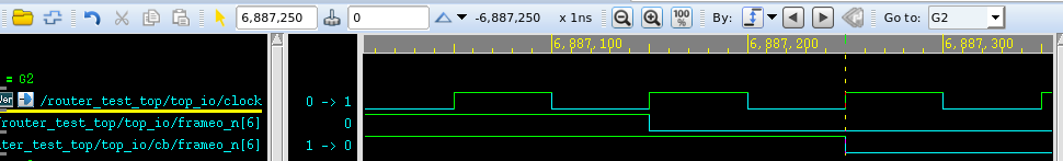
[DEBUG HGUO] 6887250.0ns, rtr_io.cb.frameo_n[da] negedge
signed and unsigned arithmetic in Verilog
With implict sign extension, the implementation of signed arithmetic is DIFFERENT from that of unsigned. Otherwise, their implementations are same.
The implementations manifest the RTL's behaviour correctly
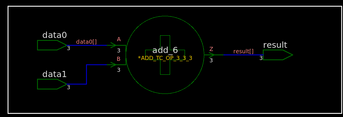
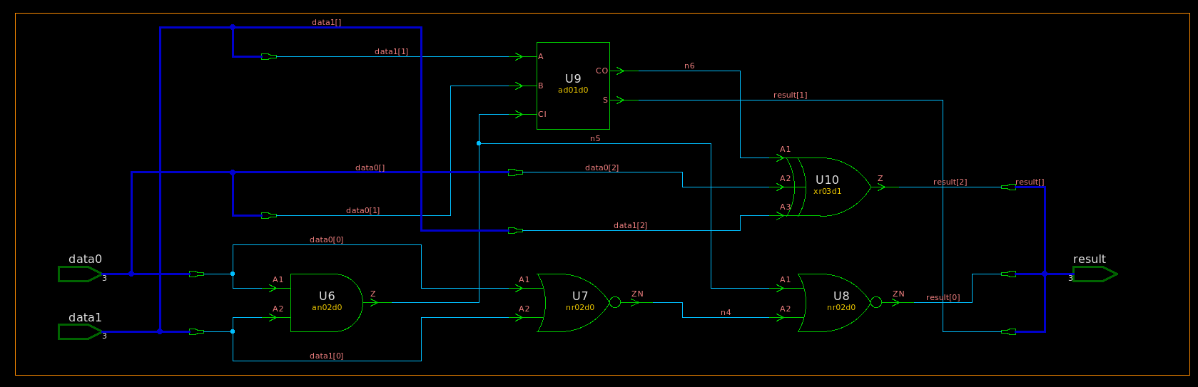
add without implicit sign extension
unsigned
rtl
1 | module TOP ( |
synthesized netlist
1 | ///////////////////////////////////////////////////////////// |
vcs compile with
-v /path/to/lib.v
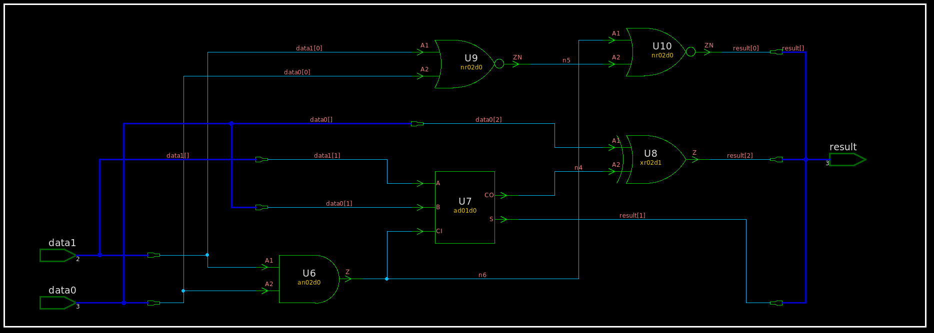
signed
rtl
1 | module TOP ( |
synthesized netlist
1 | ///////////////////////////////////////////////////////////// |
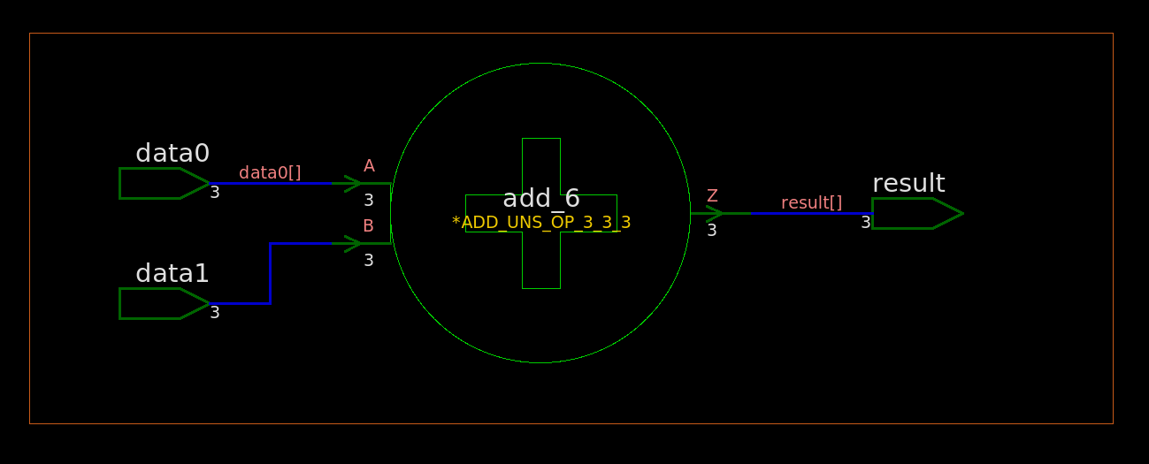
add WITH implicit sign extension
unsigned with 0 extension
rtl
1 | module TOP ( |

synthesized netlist
1 | ///////////////////////////////////////////////////////////// |
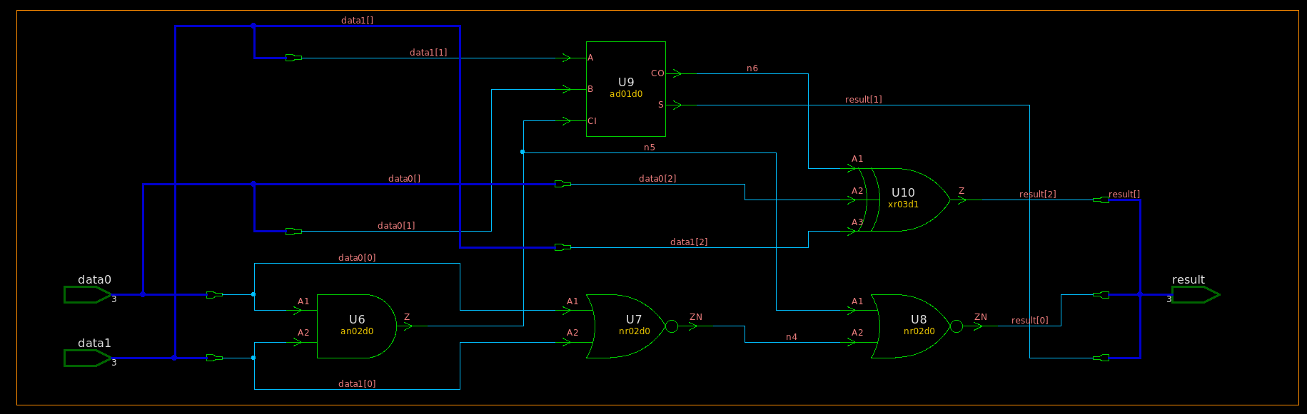
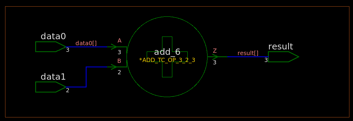
signed with implicit sign extension
rtl
1 | module TOP ( |
synthesized netlist
1 | ///////////////////////////////////////////////////////////// |
Latch Inference in Verilog
UC Berkeley CS150 Lec #20: Finite State Machines [slides]
always@( * )
always@( * ) blocks are used to describe Combinational
Logic, or Logic Gates. Only = (blocking) assignments should
be used in an always@( * ) block.
Latch Inference
If you DON'T assign every element that can be
assigned inside an always@( * ) block every time that
always@( * ) block is executed, a latch will be inferred
for that element
The approaches to avoid latch generation:
- set default values
- proper use of the
elsestatement, and other flow constructs
without default values
latch is generated
RTL
1 | module TOP ( |
synthesized netlist
1 | ///////////////////////////////////////////////////////////// |
add default value
Default values are an easy way to avoid latch generation
RTL
1 | module TOP ( |
synthesized netlist
1 | ///////////////////////////////////////////////////////////// |
if evaluation
signed number cast to unsigned
automatically before evaluating
1 | // tb.v |
1 | $ vlog tb.v |
Arithmetic in Verilog
unsigned + unsigned = unsigned
1 | function [7:0] satadd_uuu8b; // unsigned + unsigned = unsigned |
1'b1: overflow
signed + signed = signed
1 | function [7:0] satadd_sss8b; // signed + signed = signed |
2'b01: overflow
2'b10: underflow
signed + unsigned = unsigned
1 | function [7:0] satadd_suu8b; // signed + unsigned = unsigned |
signed + unsigned = signed
1 | function signed [7:0] satop_sus8b; //signed +/- unsigned = signed |
Overflow Detection in Verilog
Overflow Detection: [http://www.c-jump.com/CIS77/CPU/Overflow/lecture.html]
- Arithmetic operations have a potential to run into a condition known as overflow.
- Overflow occurs with respect to the size of the data type that must accommodate the result.
- Overflow indicates that the result was too large or too small to fit in the original data type.
Overflow when adding unsigned number
When two unsigned numbers are added, overflow occurs if
- there is a carry out of the leftmost bit.
Overflow when adding signed numbers
When two signed 2's complement numbers are added, overflow is detected if:
- both operands are positive and the result is negative, or
- both operands are negative and the result is positive.
Notice that when operands have opposite signs, their sum will never overflow. Therefore, overflow can only occur when the operands have the same sign.
| A | B | carryout_sum | overflow |
|---|---|---|---|
| 011 (3) | 011 (3) | 0_110 (6) | overflow |
| 100 (-4) | 100 (-4) | 1_000 (-8) | underflow |
| 111 (-1) | 110 (-2) | 1_101 (-3) | - |
carryout information ISN'T needed to detect overflow/underflow for signed number addition
EXTBIT:MSB
extended 1bit and msb bit can be used to detect overflow or underflow
1 | reg signed [1:0] acc_inc; |
2'b01: overflow, up saturation
2'b10: underflow, down saturation
2's complement negative number
- Flip all bits
- Add 1.
N-bit signed number \[ A = -M_{N-1}2^{N-1}+\sum_{k=0}^{N-2}M_k2^k \] Flip all bits \[\begin{align} A_{flip} &= -(1-M_{N-1})2^{N-1} +\sum_{k=0}^{N-2}(1-M_k)2^k \\ &= M_{N-1}2^{N-1}-\sum_{k=0}^{N-2}M_k2^k -2^{N-1}+\sum_{k=0}^{N-2}2^k \\ &= M_{N-1}2^{N-1}-\sum_{k=0}^{N-2}M_k2^k -1 \end{align}\]
Add 1 \[\begin{align} A_- &= A_{flip}+1 \\ &= M_{N-1}2^{N-1}-\sum_{k=0}^{N-2}M_k2^k \\ &= -A \end{align}\]
reference
Lee, Weng Fook, Weng Fook Lee, and Glaser. Learning from VLSI design experience. Springer International Publishing, 2019.
Bevan Baas, EEC281 VLSI Digital Signal Processing, [https://www.ece.ucdavis.edu/~bbaas/281/]