ESD & Latchup
CDM (Charged Device Model)
Jordan Davis, Samsung Electronics. Full-Chip CDM Analysis: Is Static Simulation Enough? [https://www.synopsys.com/content/dam/synopsys/implementation&signoff/electrical-layout-verification-documents/esd-workshop-2021-pres.pdf]
M. Etherton et al., "A new full-chip verification methodology to prevent CDM oxide failures," 2015 37th Electrical Overstress/Electrostatic Discharge Symposium (EOS/ESD), Reno, NV, USA, 2015 [pdf]
P.E. Allen 2021. Lesson 4 – ESD Input Circuit Protection [https://aicdesign.org/wp-content/uploads/2021/05/Lesson04_ESD_Input_Ckt_Protection210323.pdf]
M. Di, H. Wang, F. Zhang, C. Li, Z. Pan and A. Wang, "Does CDM ESD Protection Really Work?," 2019 IEEE Workshop on Microelectronics and Electron Devices (WMED), Boise, ID, USA, 2019 [https://sci-hub.se/10.1109/WMED.2019.8714145]
On-Chip Decoupling Capacitors
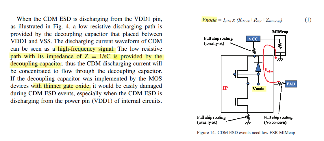
Y. -C. Huang and M. -D. Ker, "Study on CDM ESD Robustness Among On-Chip Decoupling Capacitors in CMOS Integrated Circuits," in IEEE Journal of the Electron Devices Society, vol. 9, pp. 881-890, 2021 [pdf]
Y. -C. Huang and M. -D. Ker, "Investigation of CDM ESD Protection Capability Among Power-Rail ESD Clamp Circuits in CMOS ICs With Decoupling Capacitors," in IEEE Journal of the Electron Devices Society, vol. 11, pp. 84-94, 2023
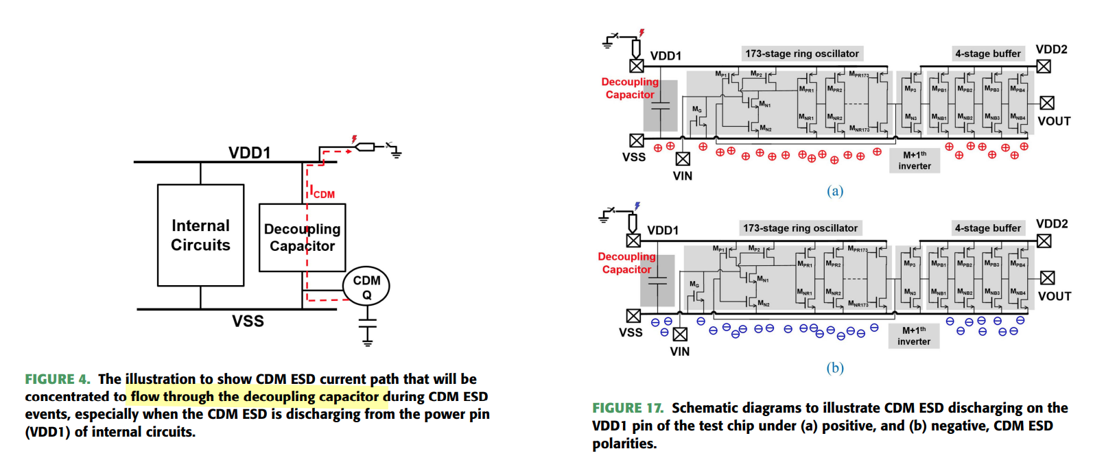
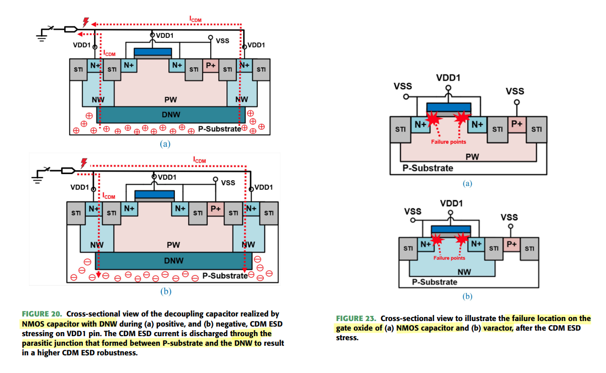
NMOS capacitor with DNW owing to the parasitic junction that formed between P-substrate and the DNW to reduce the probability of ESD damage on the thin gate oxide layer of NMOS capacitor.
Therefore, it results in higher CDM ESD robustness than that of the other two designs with decoupling capacitors realized by of varactor and NMOS capacitor
Circuit-Level CDM Model
H. Wang, F. Zhang, C. Li, M. Di and A. Wang, "Chip-Level CDM Circuit Modeling and Simulation for ESD Protection Design in 28nm CMOS," 2018 14th IEEE International Conference on Solid-State and Integrated Circuit Technology (ICSICT), Qingdao, China, 2018
—. (2018). A Chip-Level CDM ESD Protection Circuit Modeling and Simulation Method and Experimental Verification. UC Riverside [https://escholarship.org/content/qt1355v6vs/qt1355v6vs.pdf]
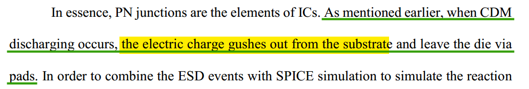
Today's cognition ondie CDM charge is stored in the substrate
The circuit model is divided into three parts:
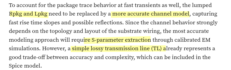
IC package
substrate resistance & capacitance
protection devices & circuit elements
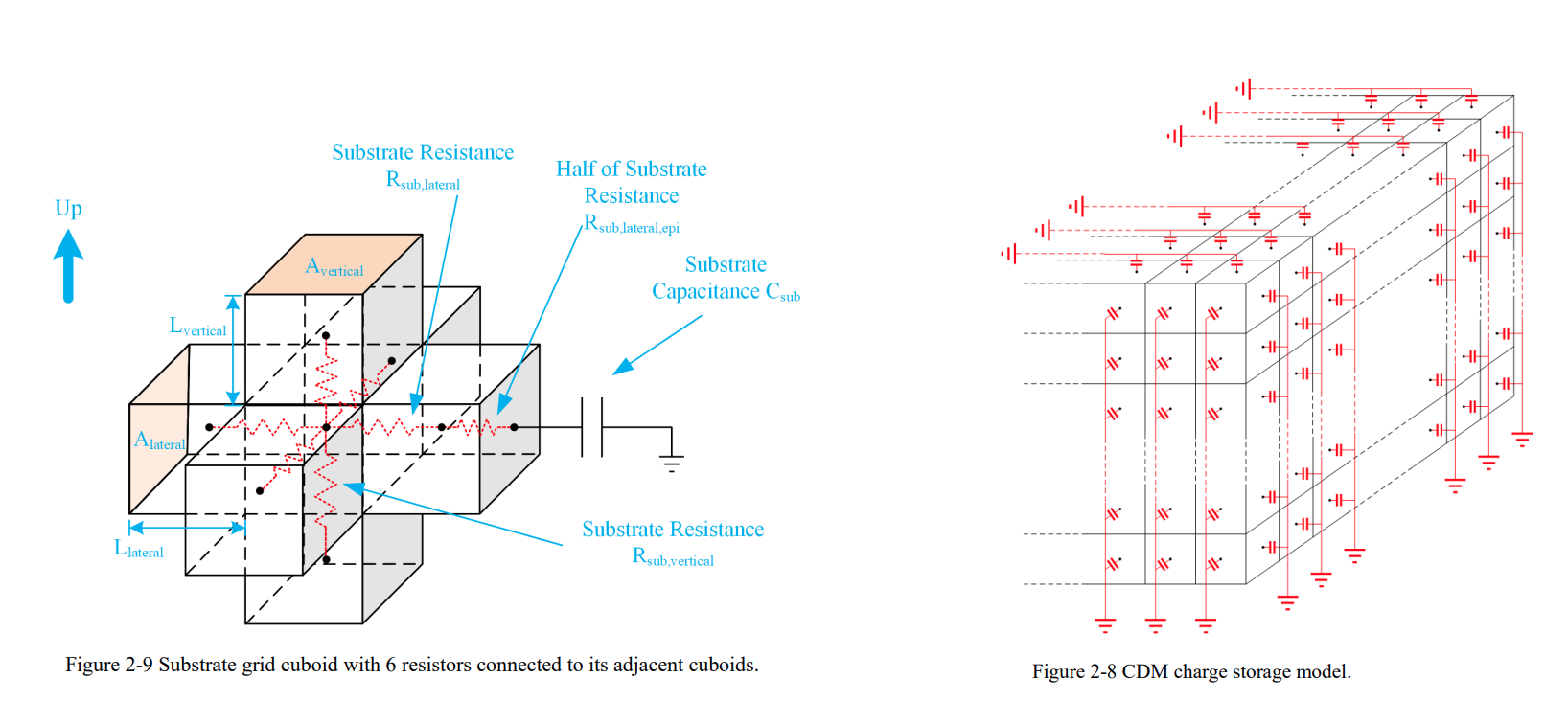
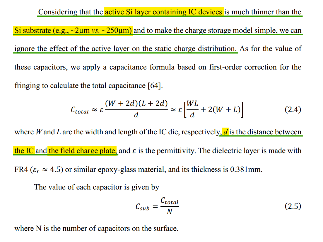
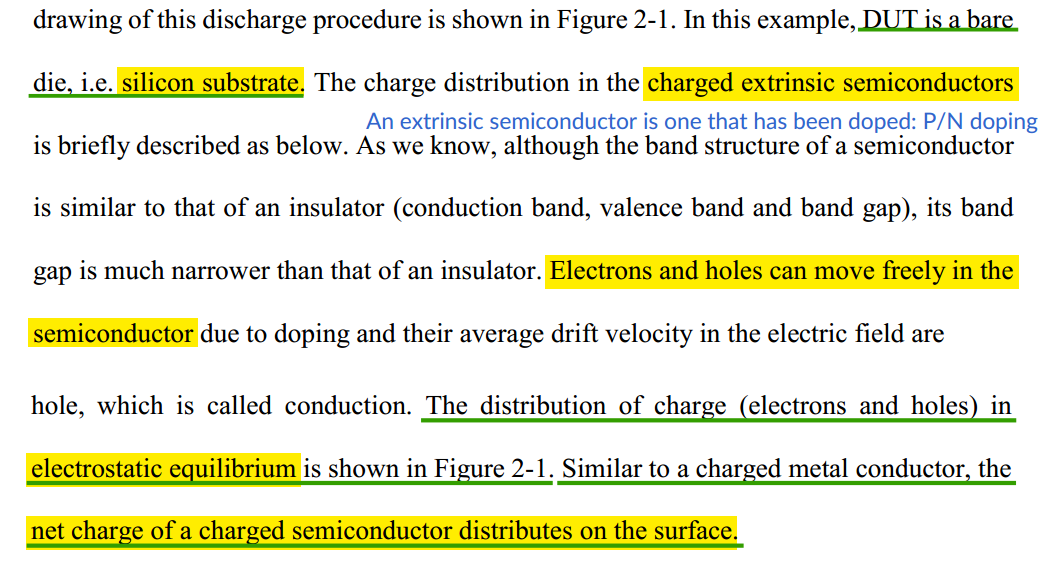
all charges are considered be distributed to the surface of an IC die, i.e., Si substrate
The surface-stored charges are modeled using the capacitors at the surfaces of the IC substrate
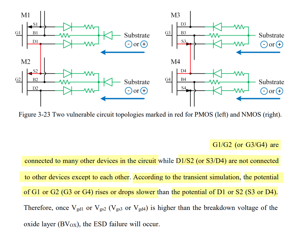
A Vulnerable Circuit Topology — cascode topology
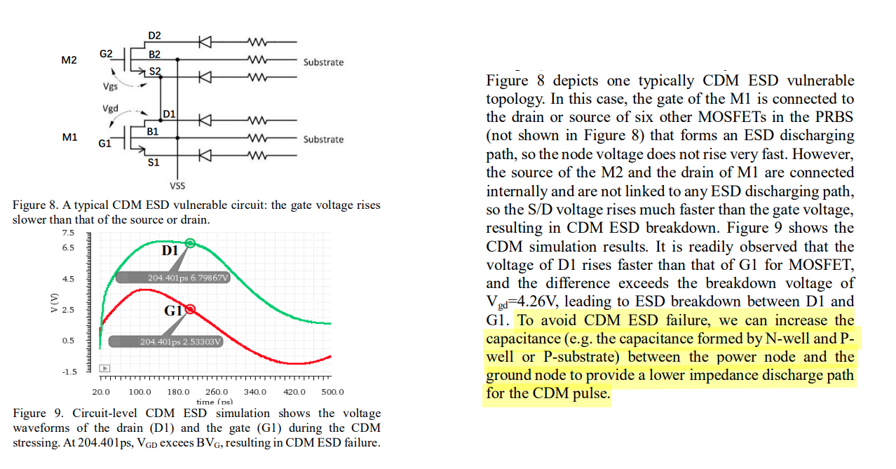
Parasitic Capacitance Path
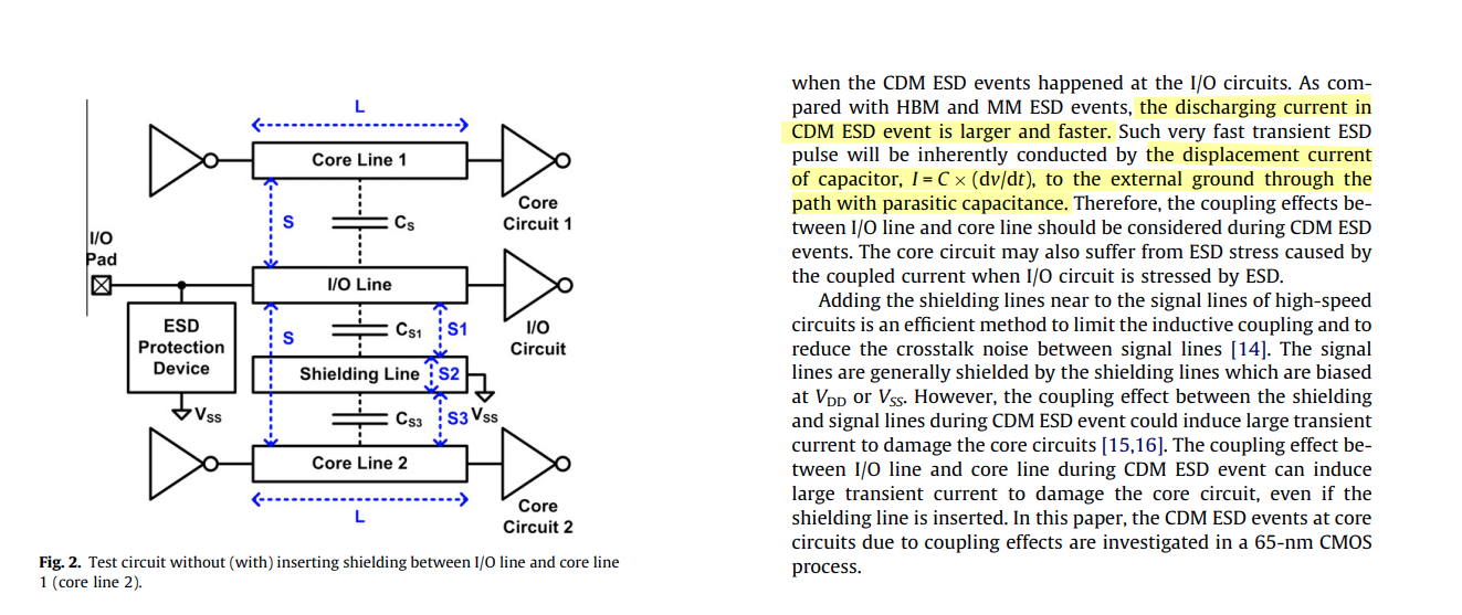
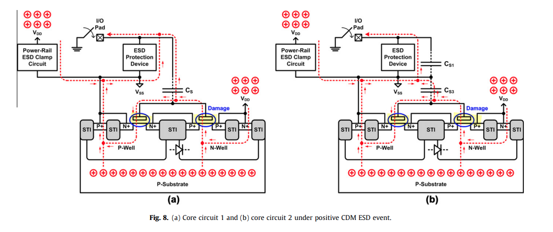
Lin, Chun-Yu, Tang-Long Chang and Ming-Dou Ker. "Investigation on CDM ESD events at core circuits in a 65-nm CMOS process." Microelectron. Reliab. 52 (2012) [pdf]
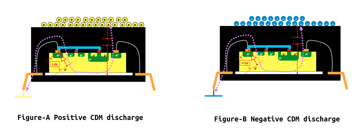
CDM ESD issue due to the coupled current when I/O circuit is stressed by CDM ESD
negative CDM ESD event
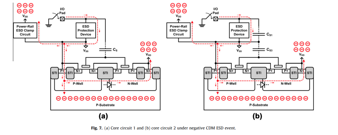
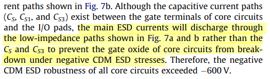
positive CDM ESD event
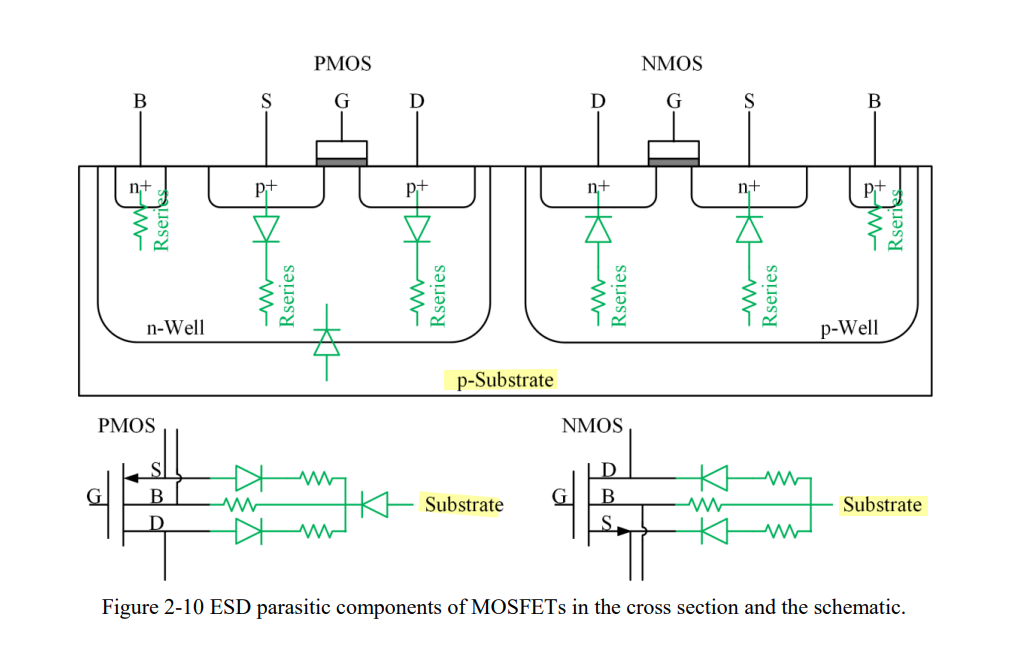
CDM Failure Mechanisms
- reverse S/D junctions
- capacitively coupled through the gate
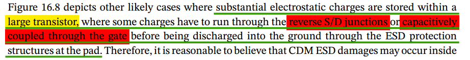
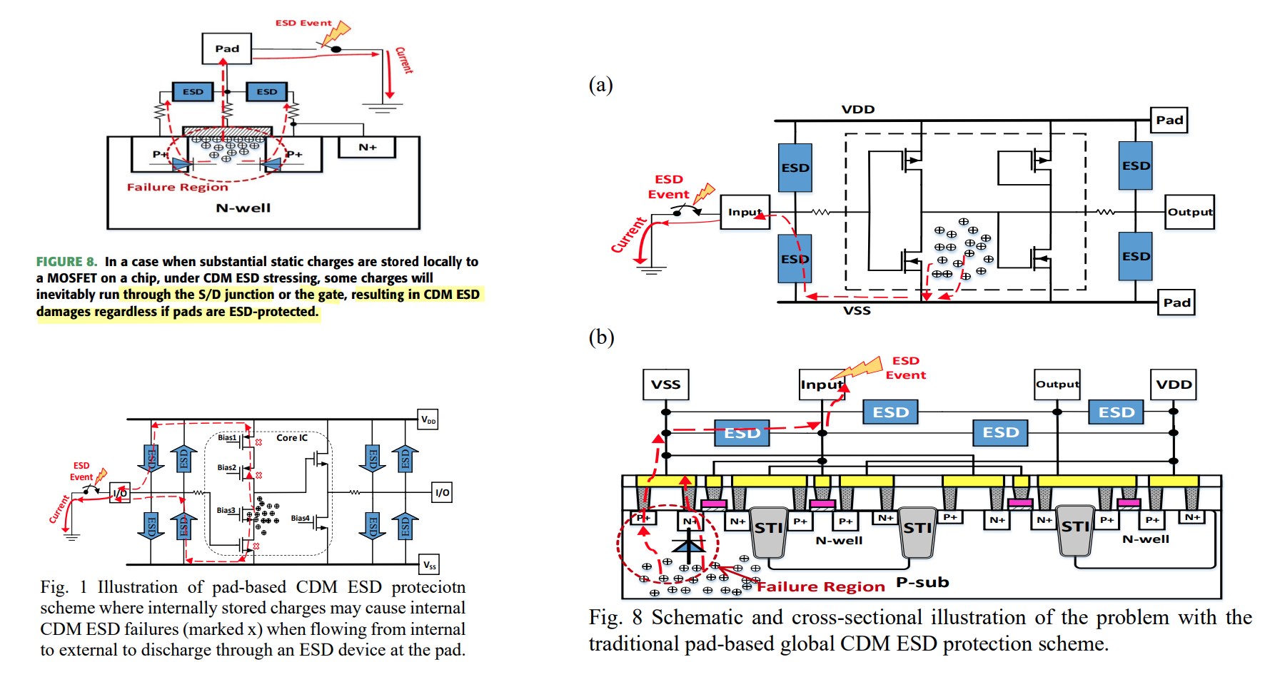
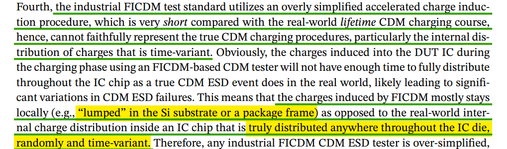
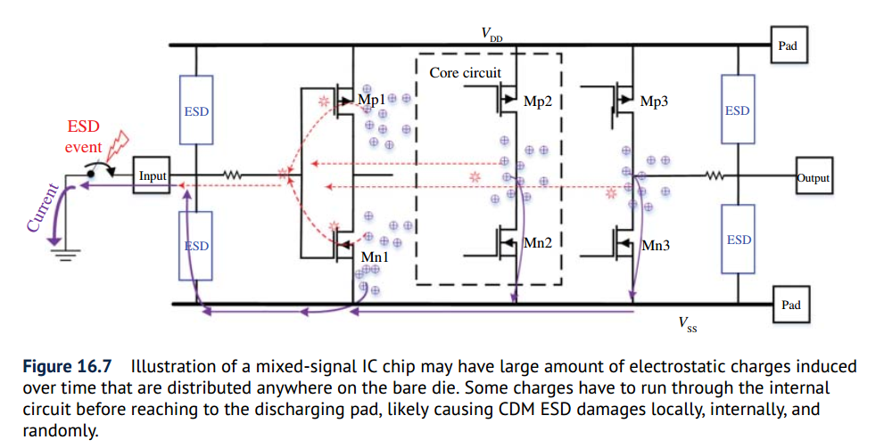
For a bare Si die, the charges induced by whatever procedures, are stored inside the IC die randomly, unpredictably and anywhere, e.g., in the substrate, along the metal rails or locally to transistors
M. Etherton et al., "A new full-chip verification methodology to prevent CDM oxide failures," 2015 37th Electrical Overstress/Electrostatic Discharge Symposium (EOS/ESD), Reno, NV, USA, 2015 [https://www.synopsys.com/content/dam/synopsys/implementation&signoff/electrical-layout-verification-documents/cdm-esd-paper.pdf]
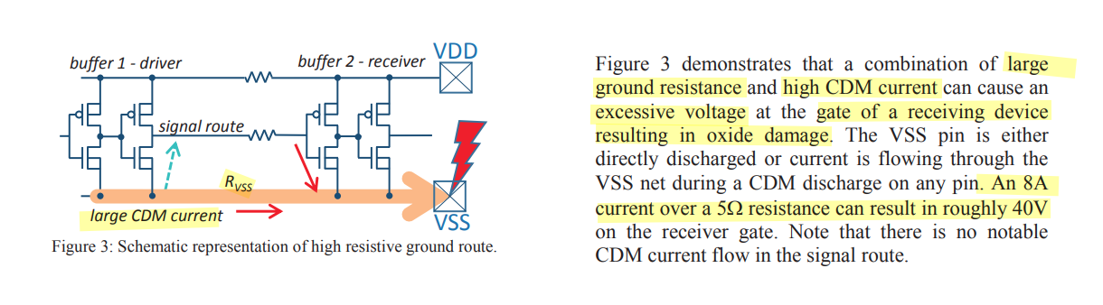
Note that there is no notable CDM current flow in the signal route
Yorgos Christoforou. Why negative polarity CDM ESD leads more often to failure [https://ycindustrial.wordpress.com/2014/01/15/why-negative-polarity-cdm-esd-leads-more-often-to-to-failure/]
?? suppose that charged package and substrate are same electric potential
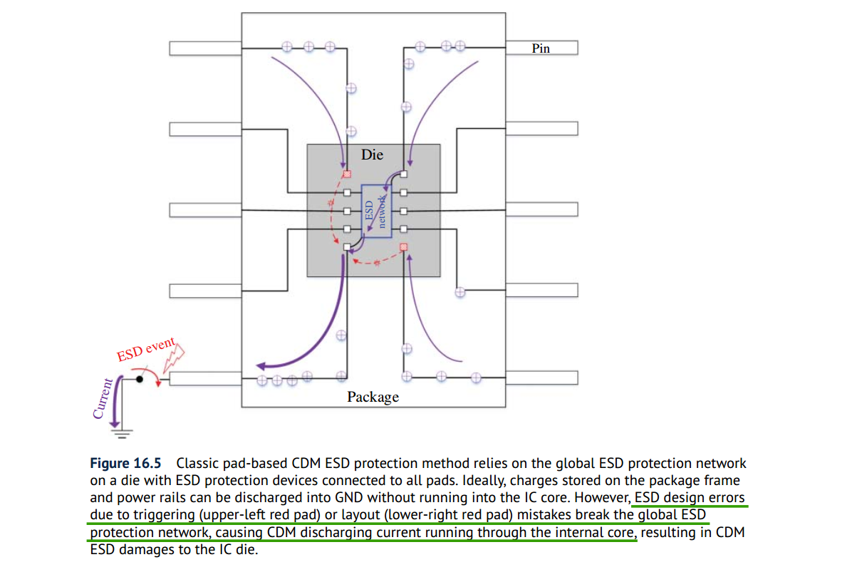
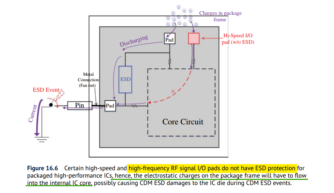
Misconception in CDM ESD Protection
Two players will affect the internal CDM discharging routing:
- the amount of electrostatic charge stored inside the IC
- more importantly, their internal distribution within a chip
Wang, Han, Feilong Zhang, Cheng Li, Mengfu Di and Albert Z. H. Wang. “Chip-Level CDM Circuit Modeling and Simulation for ESD Protection Design in 28nm CMOS.” 2018 14th IEEE International Conference on Solid-State and Integrated Circuit Technology (ICSICT) (2018) [pdf]
It is generally believed that the induced electrostatic charges are stored on the package frame and/or on the supply buses in a lumped way
induced electrostatic charges are randomly distributed throughout a bare die of mixed-signal IC, anywhere and everywhere
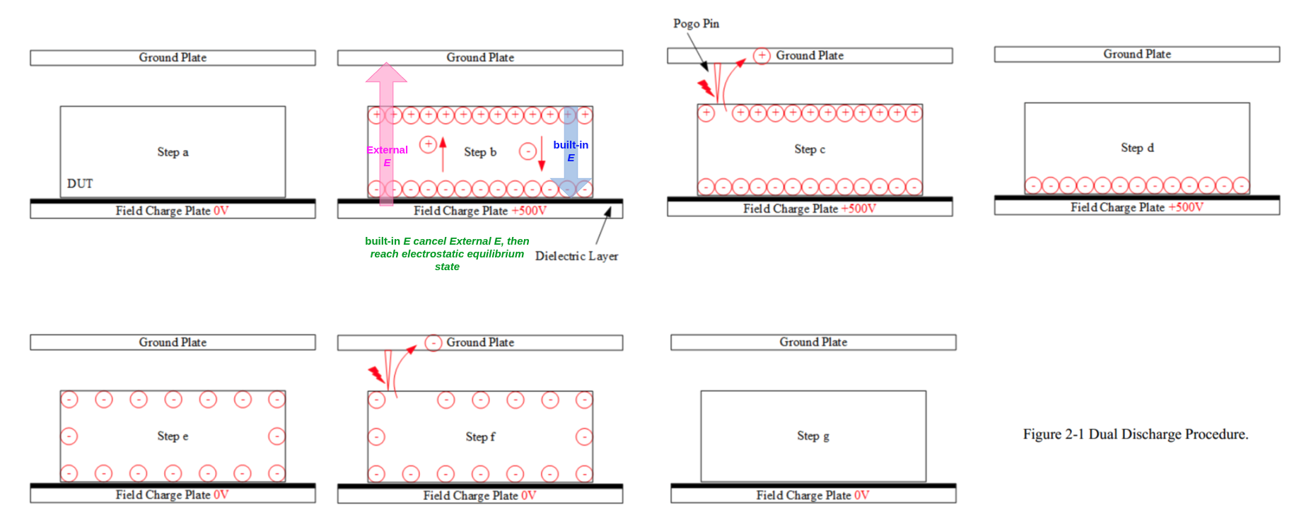
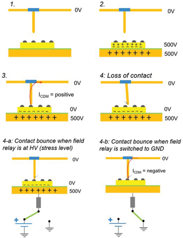
Field Induced CDM (FICDM)
Field Induced CDM Explained [https://certus-semi.com/field-induced-cdm-explained/]
 Confusion about the test procedure is
understandable because the actual process is opposite from what is
expected
Confusion about the test procedure is
understandable because the actual process is opposite from what is
expected
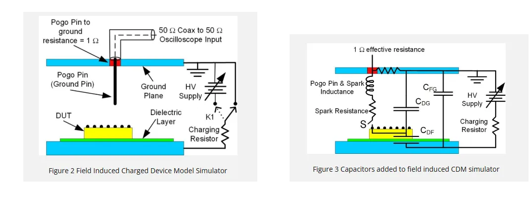
field induction does not place any charge on the device
the "discharge" when the pogo pin first touches the DUT is when the DUT is actually charged
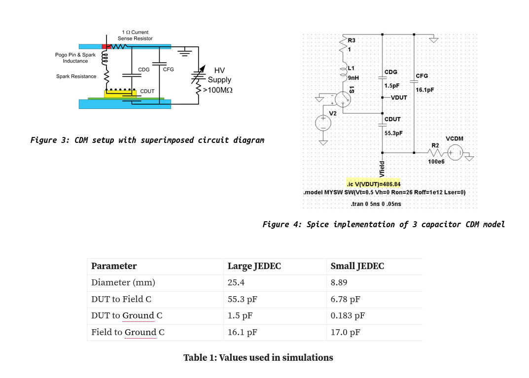
\(C_{DF}\) is the capacitance of the DUT to the field plate
\(C_{DG}\) is the capacitance of the DUT to the ground plane
\(C_{FG}\) is the capacitance of the field plate to the ground plane
\(C_{DF}\gg C_{DG}\) — the separation of the DUT from the field plate is always much less than the separation of the DUT from the ground plane
Assuming no initial charge on the DUT, with the switch S open the DC voltage between the DUT and the Field Plate is \[ V_{DF} = \frac{C_{DG}}{C_{DG} + C_{DF}}\cdot V_{HV} \approx 0 \]
- DUT potential will therefore closely track the power supply voltage
- The potential of the DUT relative to the ground plane can therefore be controlled without actually putting any net charge on the DUT
CDM Test Sequence
With the field plate at zero volts an uncharged DUT is placed on the field plate in the dead bug position and the ground plane is positioned with the pogo pin above the pin to be tested
The field plate is raised to a high potential, for example +500 V. The high value resistor ensures that the field plate changes potential relatively slowly. The slow change in potential ensures that the DUT is not damaged before the CDM event.
The potential of the DUT will closely track the field plate, reaching in excess of 450 V, although there will be no net charge on the DUT
Capacitive coupling elevates the potential of the integrated circuit to a voltage close to that of the field plate
After the voltage has stabilized the separation between the field plate and the ground plane is reduced until an arc forms between the pogo pin and the DUT pin and eventually the two pins touch.
This is equivalent to closing the switch S in Figure 3
Closing S in the circuit diagram produces a very rapid grounding of the DUT and a redistribution of charge between the three capacitors
At this point the DUT is charged and the potential between the field plate and the ground plane has fallen as the capacitor \(C_{FG}\) provides charge to the DUT
During this redistribution of charge, which usually lasts under 2 ns, the high voltage power supply and the high value resistor can be ignored because of their slow response time
After the initial redistribution of charge the field plate will slowly return to the voltage on the high voltage power supply, while the DUT remains at zero potential, but in a charged state
With the pogo pin still touching the DUT pin the HV power supply voltage is set to zero. The field plate will slowly return to zero volts and the charge on the DUT will slowly bleed off through the pogo pin.
single & dual discharge method
single discharge procedure:
single positive or single negative CDM ESD pulse is applied to DUT for individual CDM discharge
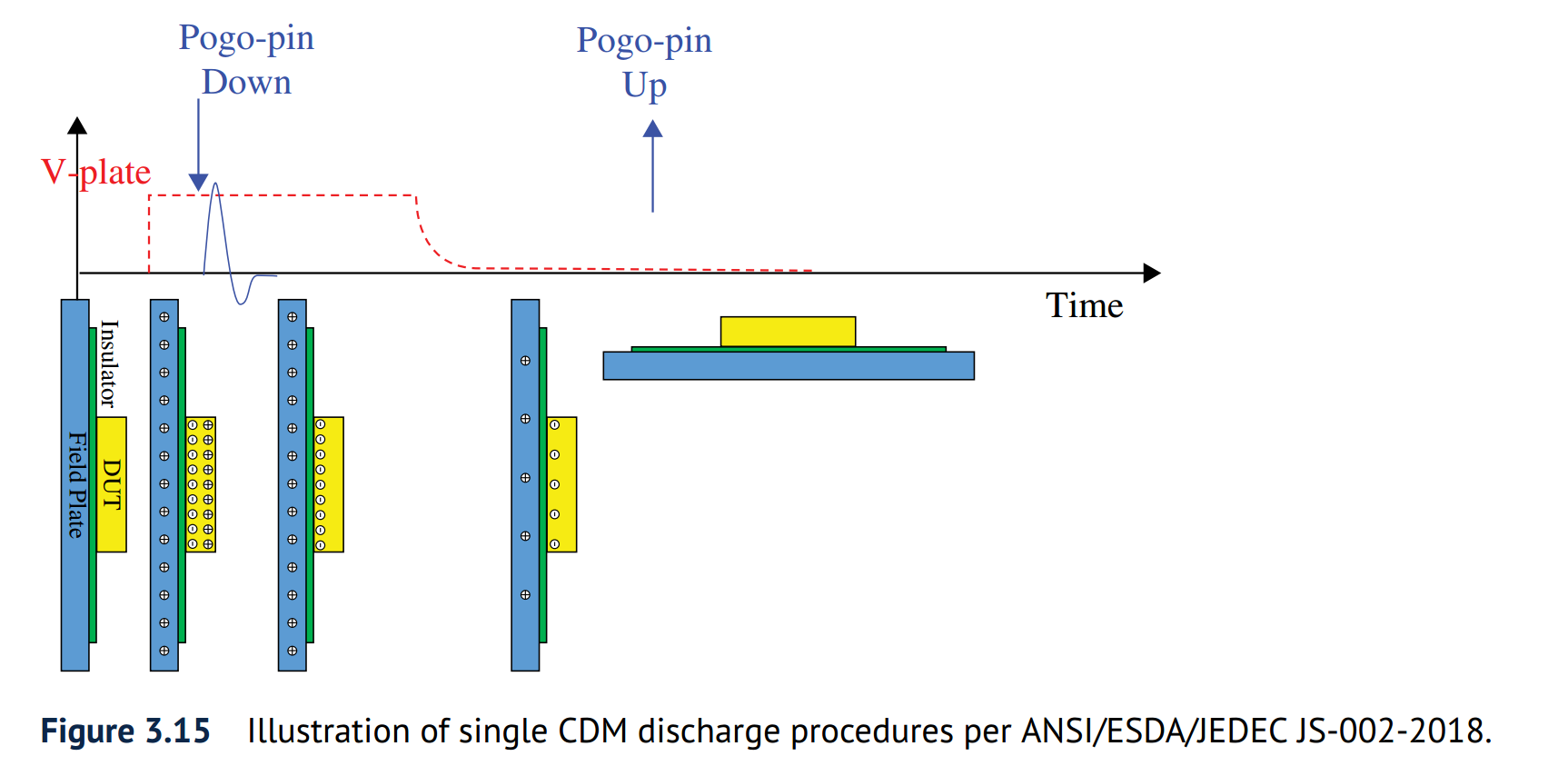
the single discharge procedure involves only one CDM discharge to stress the DUT device
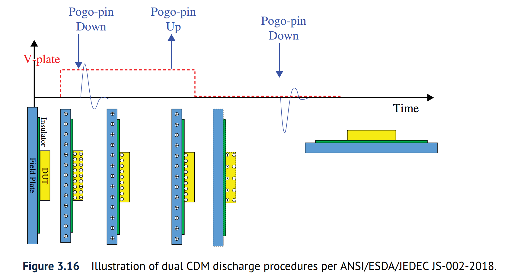
dual discharge procedure:
single positive and single negative CDM ESD pulses are applied to produce one pair of alternating polarity CDM discharges to zap the DUT
Static Induction
ESD Static Induction & Double Jeopardy Demonstration [https://youtu.be/RGN-PvAE-OI]
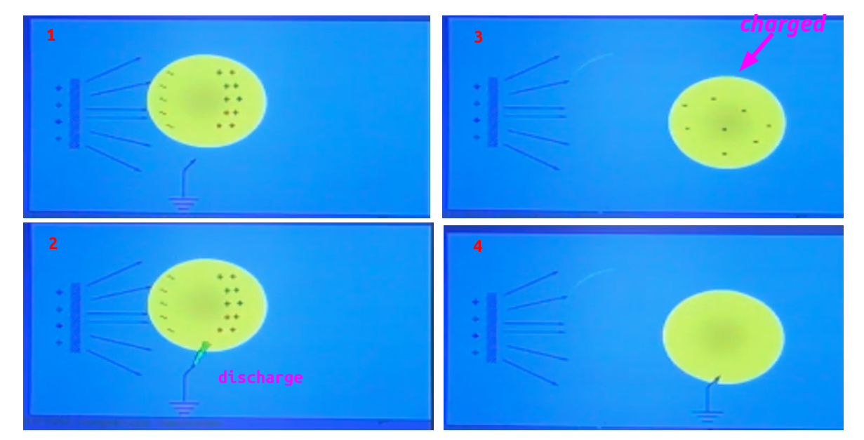
Electrostatic Equilibrium State
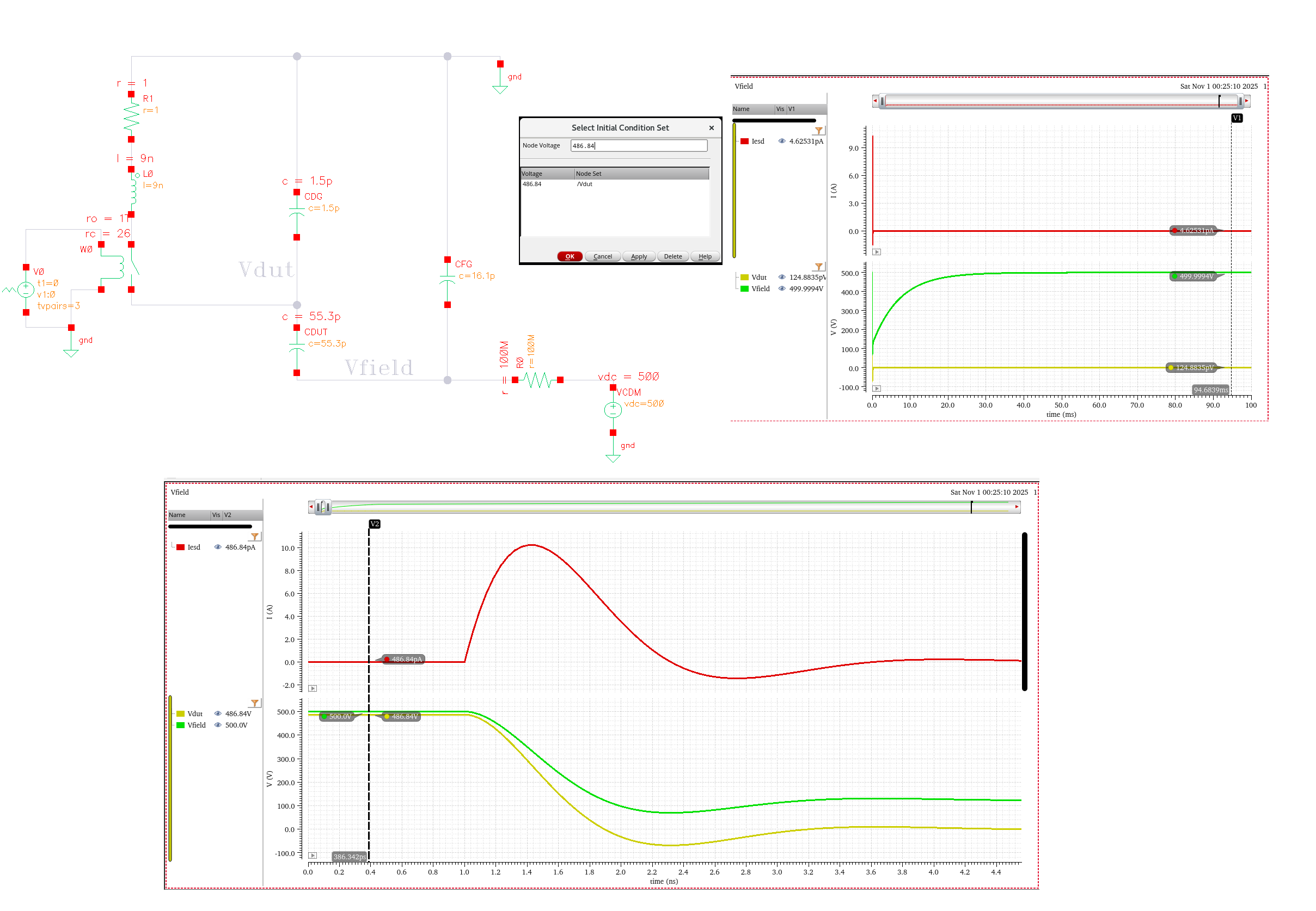
CDM Tester Model Using Spice
Robert Ashton. Simulating Small Device CDM Using Spice [https://incompliancemag.com/simulating-small-device-cdm-using-spice/]
TODO 📅
The value of CFG is also based on a parallel plate capacitor model with a peripheral capacitance term minus a capacitance representing a shielding of the Field Plate to ground plane capacitance due to the size of the device under test
Challenges of CDM Modeling for High-Speed Interface Devices [https://incompliancemag.com/challenges-of-cdm-modeling-for-high-speed-interface-devices/]
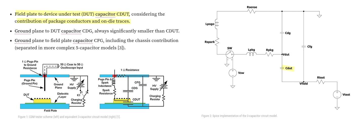
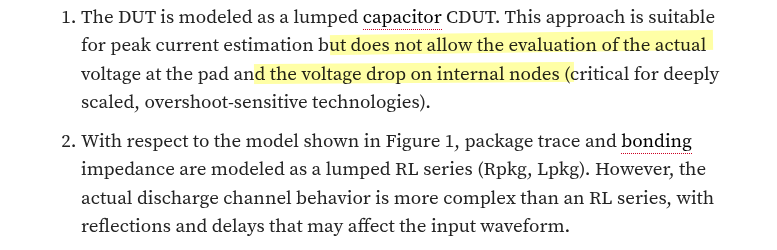
Problem Statement of a lumped capacitor CDUT
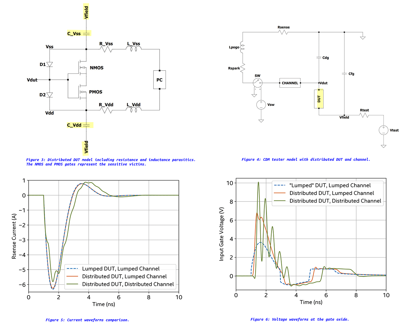
Distributed DUT model
To assess the design solutions, a distributed DUT model, as presented in Figure 3, can be plugged into the CDM tester model, replacing the lumped DUT capacitor
- The maximum voltage difference between Vdut and Vss (Vdd) should not exceed the breakdown voltage of the gates.
- On-die parasitics of Vss and Vdd nets strongly influence the actual voltage waveform at the input gate oxide. In particular, oscillations and spikes in the voltage waveform are sensed by the gate oxide and can lead to damage

Can Mechanical Movements on FI‑CDM Tester Cause Additional Zap During CDM Stress? [https://incompliancemag.com/additional-zap-during-cdm-stress/]
Protection Design
Lin, Chun-Yu and Ming-Dou Ker. “CDM ESD protection design with initial-on concept in nanoscale CMOS process.” 2010 17th IEEE International Symposium on the Physical and Failure Analysis of Integrated Circuits (2010): 1-4. [https://sci-hub.jp/10.1109/IPFA.2010.5532223]
Shih-Hung Chen, Ming-Dou Ker, Active ESD protection circuit design against charged-device-model ESD event in CMOS integrated circuits [https://sci-hub.jp/10.1016/j.microrel.2007.07.095]
Jian-Hsing Lee et al., "The study of sensitive circuit and layout for CDM improvement," 2009 16th IEEE International Symposium on the Physical and Failure Analysis of Integrated Circuits, Suzhou, China, 2009 [link]
using the deep N-well
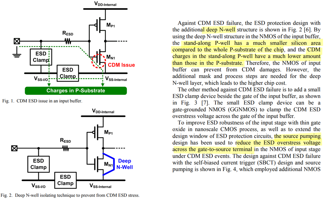
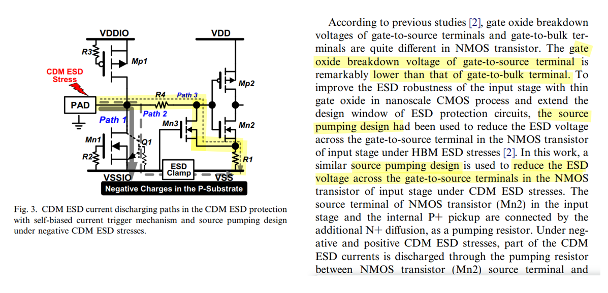
source pumping resistor
Power Clamp
Ein.019, RCCLAMP个人理解 [https://blog.eetop.cn/blog-1779684-6962653.html]
Thanks to the device scaling the area is actually reasonable.
However, the leakage becomes the main bottleneck. 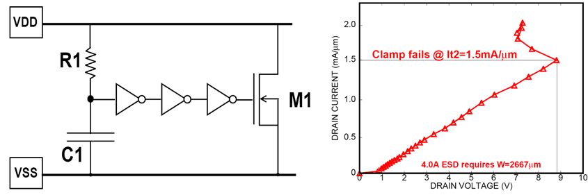


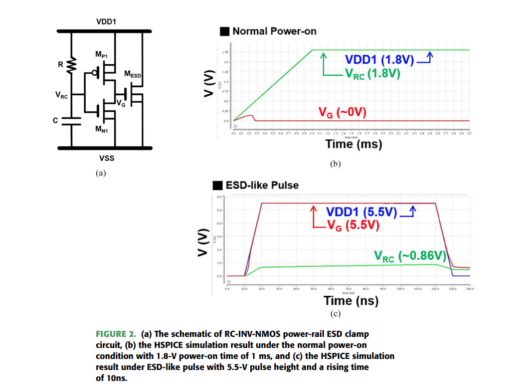
Y. -C. Huang and M. -D. Ker, "Investigation of CDM ESD Protection Capability Among Power-Rail ESD Clamp Circuits in CMOS ICs With Decoupling Capacitors," in IEEE Journal of the Electron Devices Society, vol. 11, pp. 84-94, 2023 [pdf]
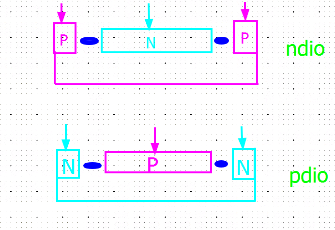
Dual Stacked Diodes
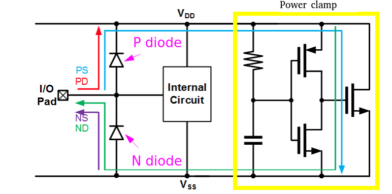
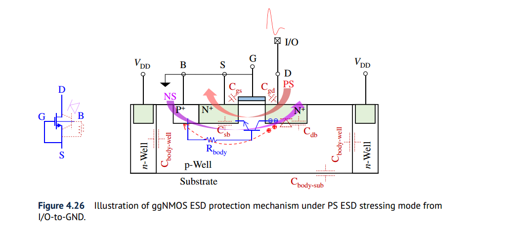
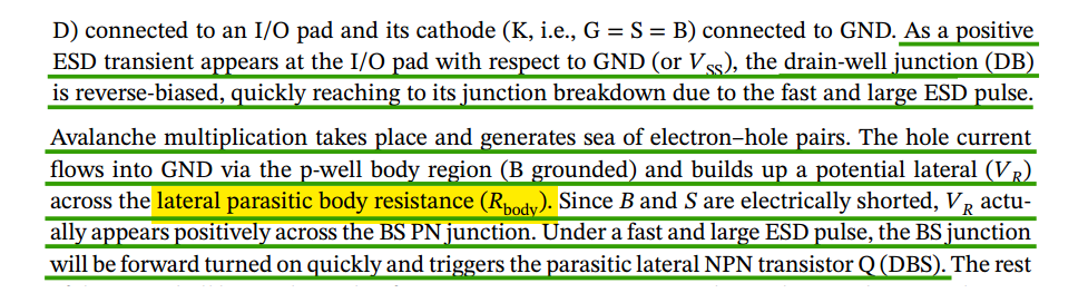
PS: I/O to GND positively
NS: I/O to GND negatively
PD: I/O to VDD positively
ND: I/O to VDD negatively
Dual diode should be used with power clamp for PS and ND path
PMOS power clamp

Reverse diode for 1.8V/3.3V power clamp
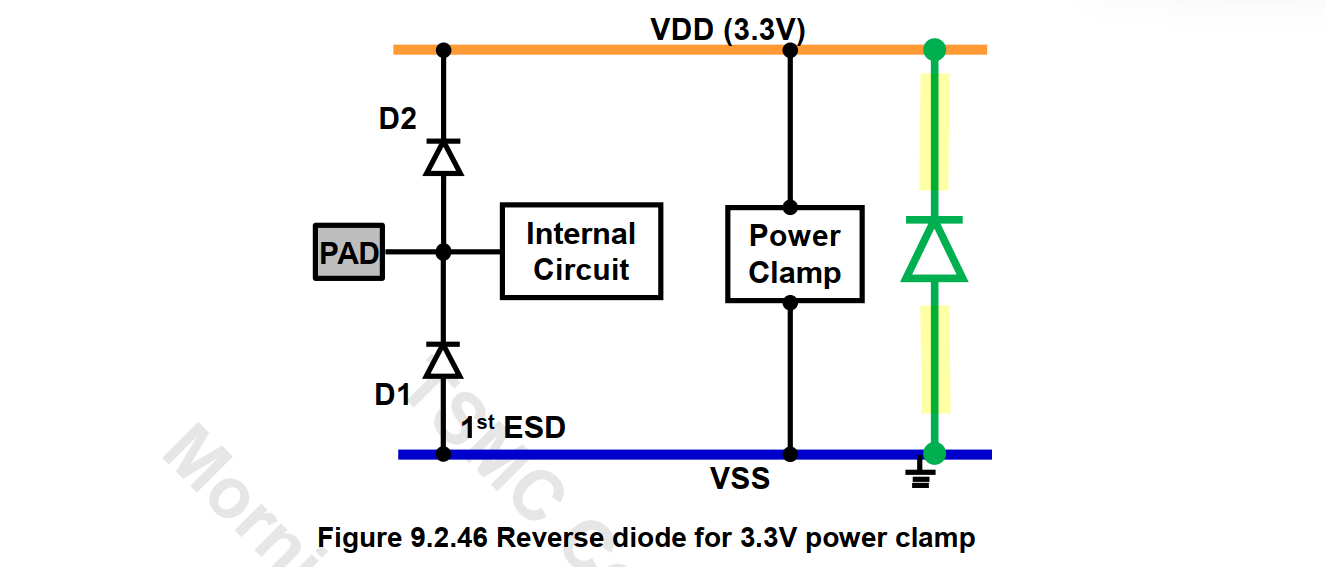
The resistance between HIA Diode and power/ground bump is constricted in PERC check
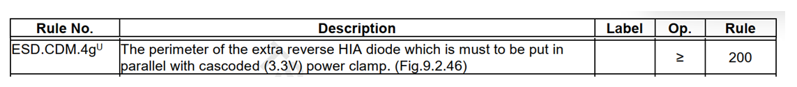
B2B Diode
M. Etherton et al., "A new full-chip verification methodology to prevent CDM oxide failures," 2015 37th Electrical Overstress/Electrostatic Discharge Symposium (EOS/ESD), Reno, NV, USA, 2015 [https://www.synopsys.com/content/dam/synopsys/implementation&signoff/electrical-layout-verification-documents/cdm-esd-paper.pdf]
also known as anti-parallel ESD diode
pdiode is usually employed as B2B diode
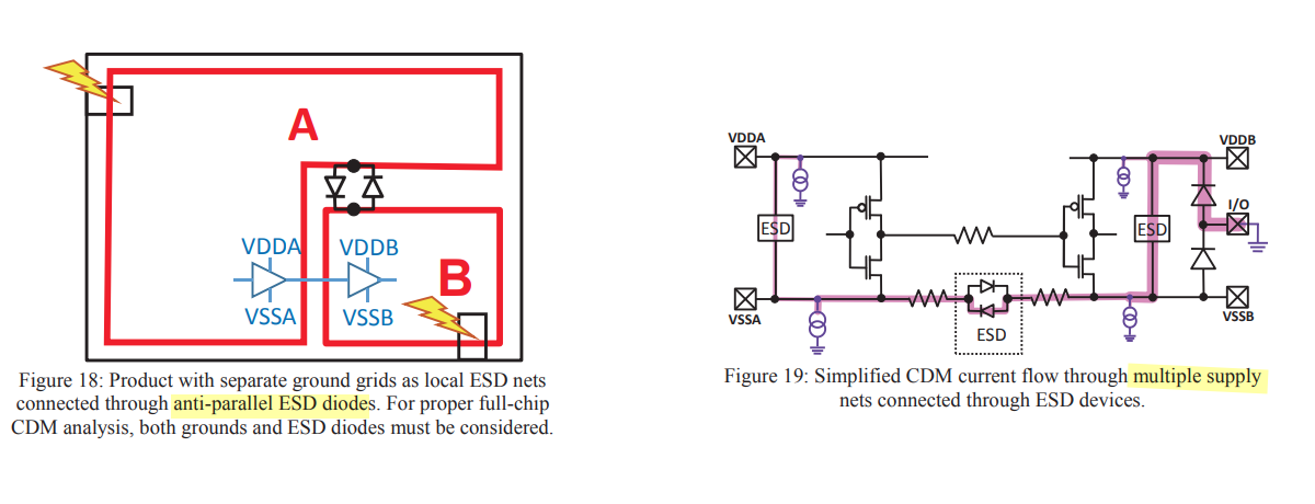
PERC
Frank Feng. New Approach For Full Chip Electrical Reliability Verification [pdf]
Calibre PERC Catalog Test-Cases & Common Examples Version 2.0
K. -H. Meng, M. Khazhinsky and J. C. Smith, "Effective ESD Design Through PERC Programming," 2023 45th Annual EOS/ESD Symposium (EOS/ESD), Riverside, CA, USA, 2023
What is Programmable Electrical Rules Checking? [https://www.synopsys.com/glossary/what-is-programmable-electrical-rules-checking.html]
Dina Medhat. Programmable Electrical Rule Checking (PERC) [pdf]
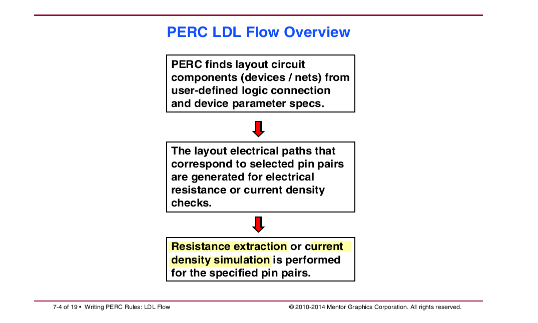
Programmable Electrical Rules Checking (PERC) is a method for checking reliability issues of integrated circuit (IC) designs that cannot be checked with design rule checking (DRC) or layout versus schematic (LVS).
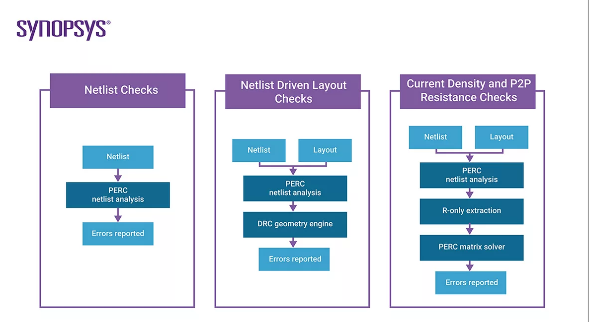
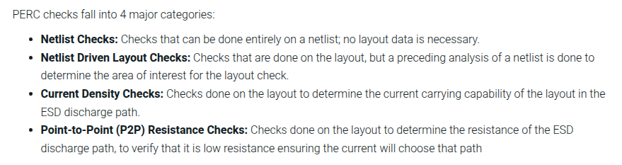
| Topology (Circuit Connection and Device Size) | Check ESD protection scheme |
|---|---|
| LDL (Logic-Driven-Layout DRC) | Check Latch-up rules |
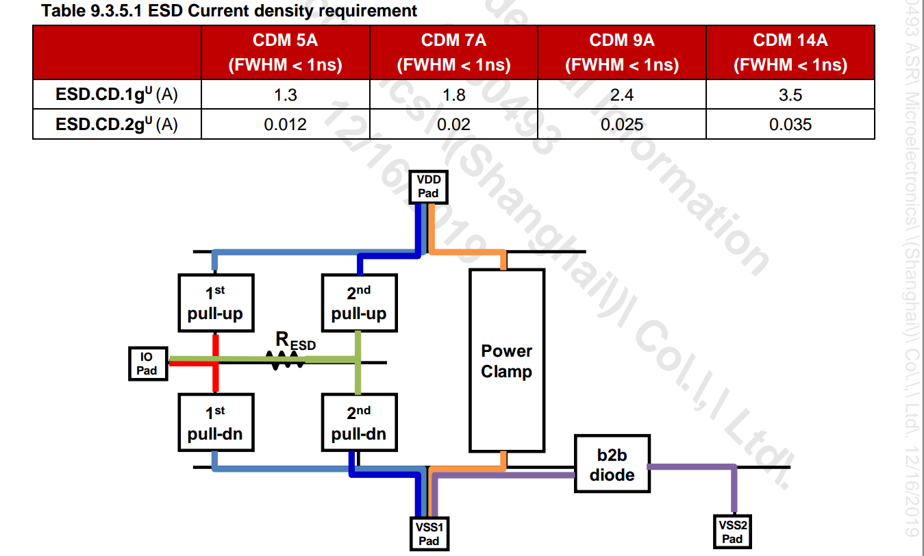
| CD (Current Density) | Check primary, secondary ESD discharge path |
| P2P (Point-to-Point Resistance) | Check I/O to power-clamp path |
pad_info
1 | // Define PAD Voltage |
above <x0-coor y0-coor> and <x1-coor y1-coor> are shorted together, in this way the two bump can share power clamp

in TSMC
Topology (Circuit Connection and Device Size) Check ESD protection scheme LDL (Logic-Driven-Layout DRC) Check Latch-up rules CD (Current Density) Check primary, secondary ESD discharge path P2P (Point-to-Point Resistance) Check I/O to power-clamp path
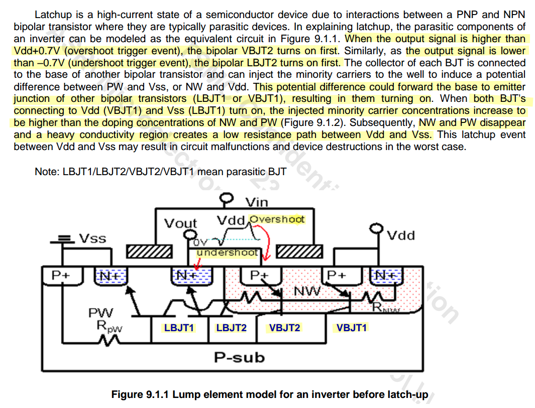
Latchup
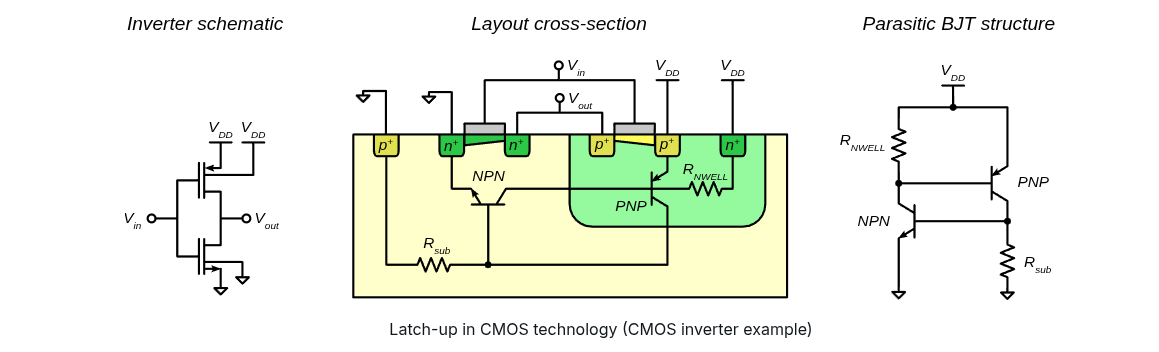
Latch-up in CMOS circuits: threat or opportunity (part 1) [https://monthly-pulse.com/2021/01/05/latch-up-in-cmos-circuits-threat-or-opportunity-part-1/]
Latch-up in CMOS circuits: threat or opportunity (part 2) [https://monthly-pulse.com/2021/01/05/latch-up-in-cmos-circuits-threat-or-opportunity-part-2/]
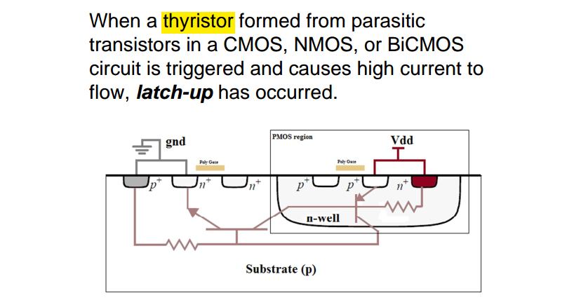
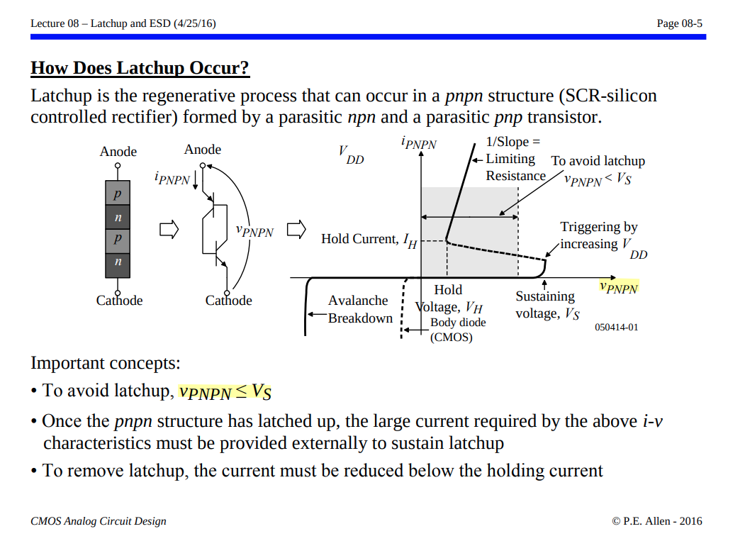
This can happen when a parasitic thyristor, which is essentially a pair of interconnected transistors, is triggered into a latched state, leading to sustained current flow and potential device failure.
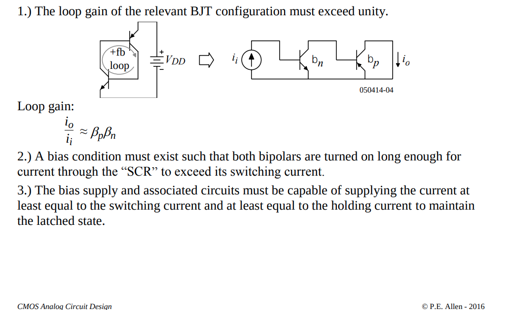
Necessary Conditions
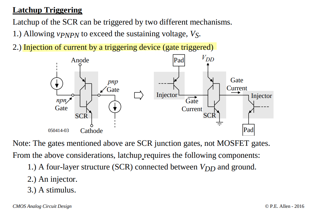
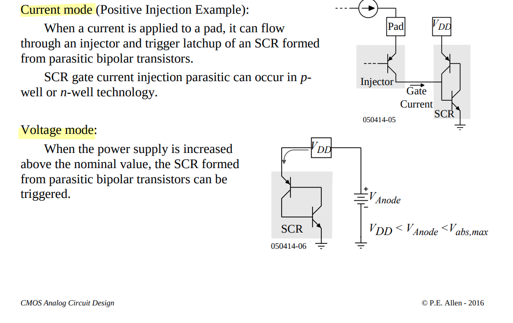
Trigger Modes
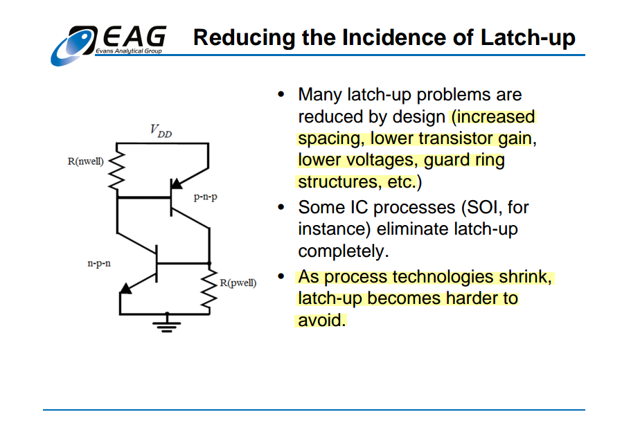
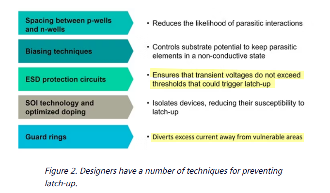
latchup-prevention technique
Technical Paper Ensuring latch-up guard rings ESDA rules using Calibre PERC [https://resources.sw.siemens.com/en-US/technical-paper-ensuring-latch-up-guard-rings-esda-rules-using-calibre-perc/]
Protect against ESD by ensuring latch-up guard rings [https://semiwiki.com/eda/362551-protect-against-esd-by-ensuring-latch-up-guard-rings/]
Guard Rings
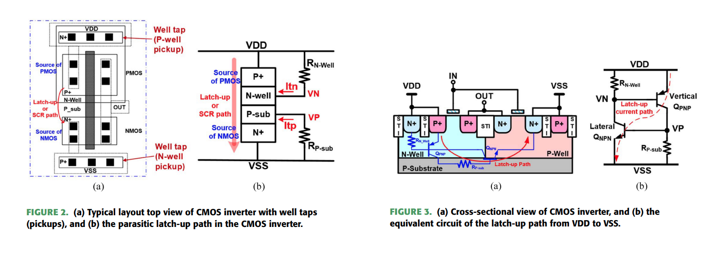
One important technique is the use of guard rings, the heavily doped regions surrounding sensitive components on the IC to divert excess current away from vulnerable areas, thereby reducing the likelihood of latch-up occurrence
These guard rings not only function as barriers against parasitic thyristor (SCR) formation but also serve to isolate different regions of the IC, minimizing unwanted electrical interactions and maintaining pathway integrity
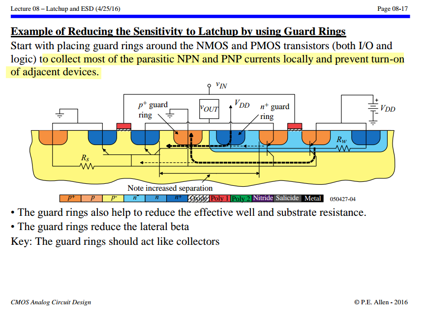
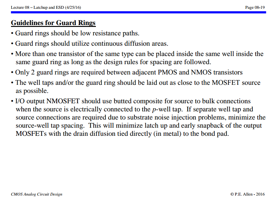
P.E. Allen - 2016. CMOS Analog Circuit Design: Lecture 08 – Latchup and ESD (4/25/16) [https://aicdesign.org/wp-content/uploads/2018/08/lecture08-160425.pdf]
[https://analoghub.ie/category/Layout/article/layoutDependentEffects#Latchup]
Latch-Up triggers:
- Power up
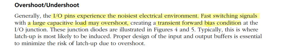
- Overshoot voltages and currents
- Substrate noise
- ESD occurrences
Latch-up key points:
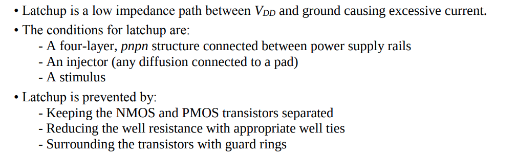
- State of an IC when it is made inoperable by a parasitic shorting of VDD and VSS;
- Triggering of a Low Impedance High Current state between supplies;
- High Current State remains even when trigger signal is removed.
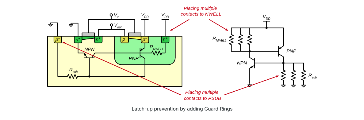
Latch-up prevention:
- Guard rings has a lot of contacts, providing a strong VDD/Ground potential;
- Guard rings add more parallel resistance to the NWELL/Substrate, thereby reducing parasitic resistors;
- NWELL/substrate potentials are held around VDD/Ground, no positive feedback is formed.
Transient-Induced Latchup
OD injector with different noise level
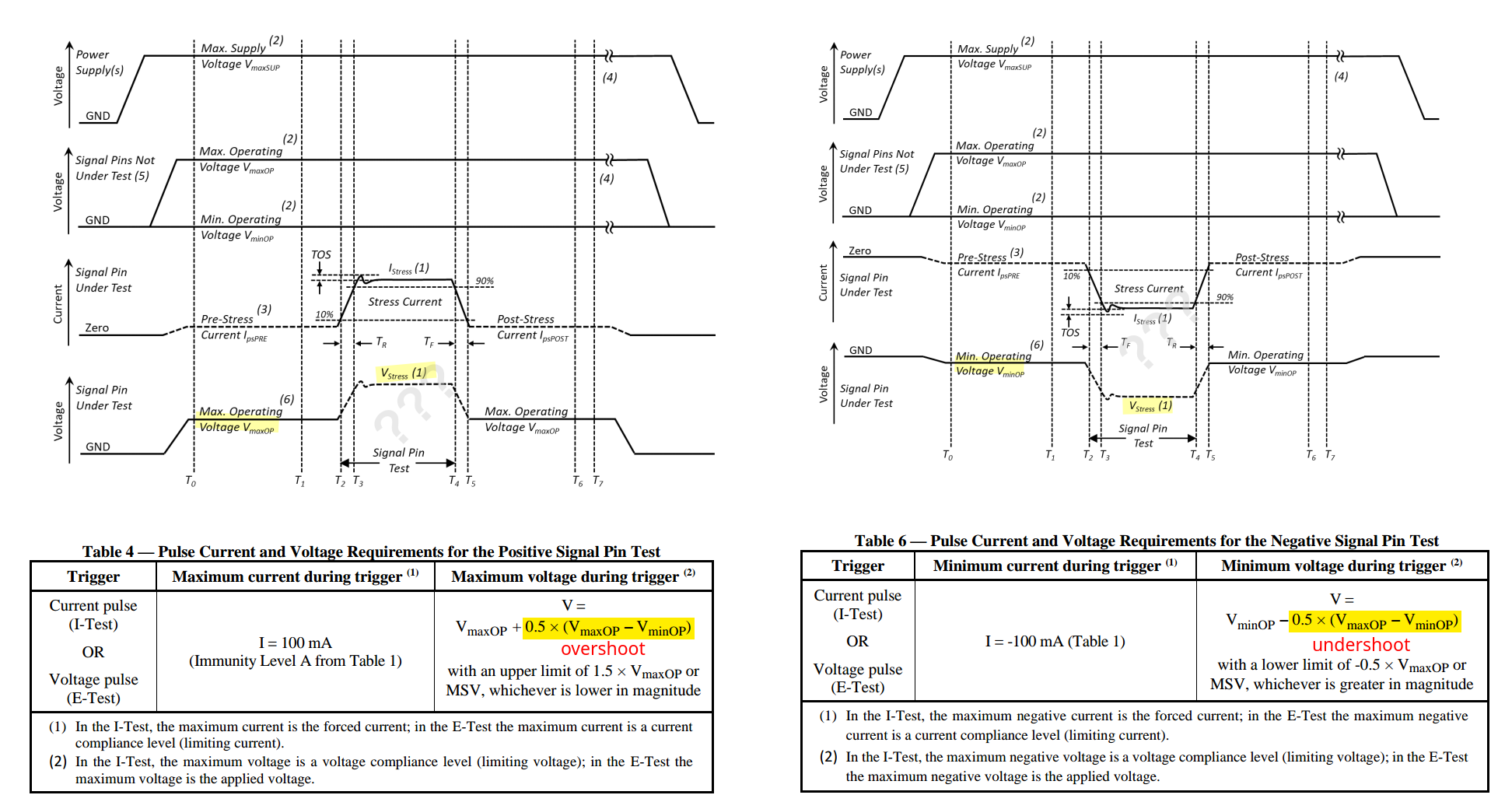
JEDEC STANDARD IC Latch-Up Test JESD78F.01 (Revision of JESD78F dated January 2022 [https://www.jedec.org/sites/default/files/docs/JESD78D.pdf]
Latch up DRC
藍色天空. 版图Latch up DRC规则解读 [https://www.kaixinspace.com/latch-up-rule/]
—. 一文搞懂闩锁效应(Latch up)[https://www.kaixinspace.com/latch-up/]
RES200
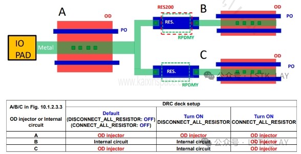
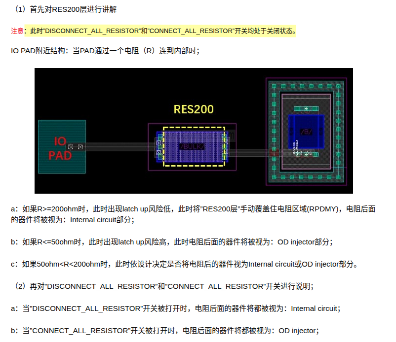
If the reistance of RESD is less than 200ohm and covered by RES200, it will be flagged by warning
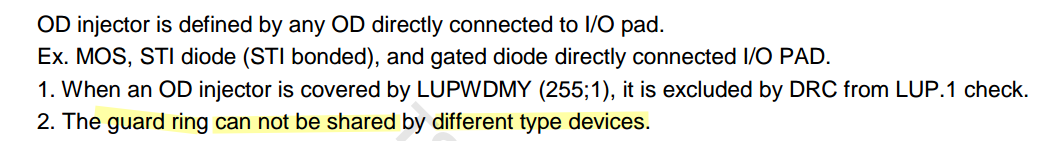
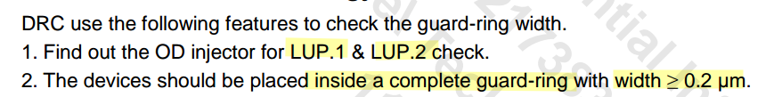
LUP.1
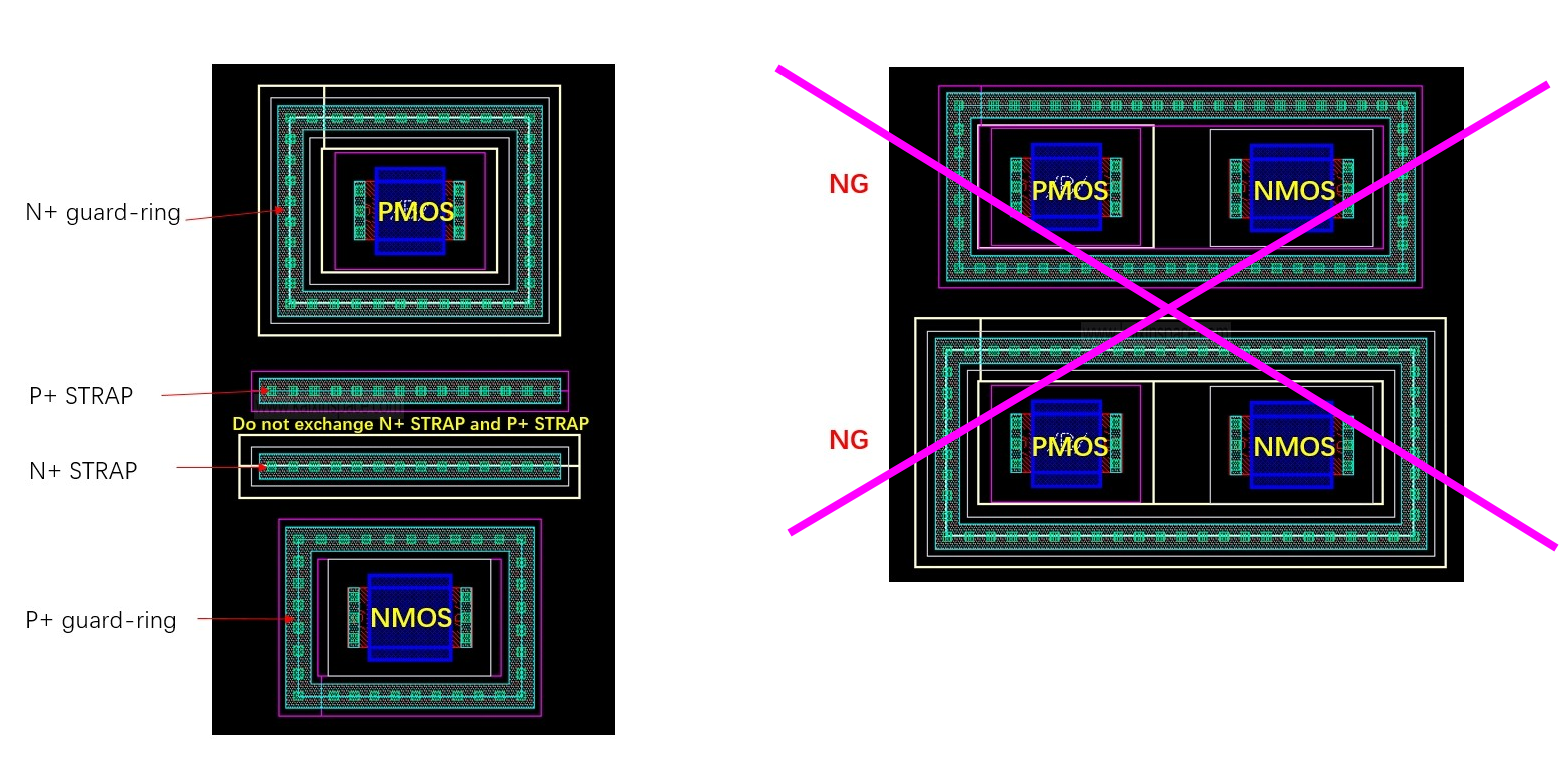
检查对象:被视为OD injector的部分。
检查内容:
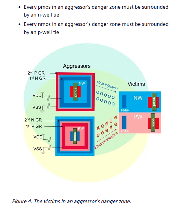
任何的N+ OD都必须被P+ guardring围绕;或者任何P+ OD都必须被N+ guardring围绕;
LUP.2
检查对象:对距离OD injector区域15um范围内的MOS OD
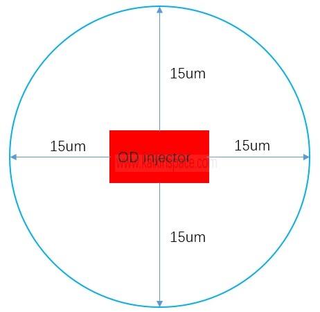
对上述检查对象进行LUP.1检查
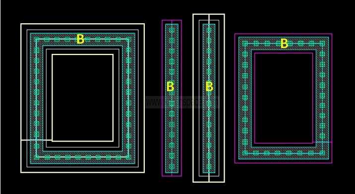
LUP.4
检查对象及内容:OD injector区域以及距离此区域15um以内的guardring或STRAP中的OD宽度B都要大于等于一定值。
Diode in ESD Protection
A diode can operate in both forward and reverse modes for ESD protection.
\(R_{ON}\) for a forward-biased diode is lower than that for a reverse-biased diode
One major disadvantage of a forward diode-string for ESD protection is that the leakage current (Ileak) may be enlarged due to the Darlington effect in the diode-string
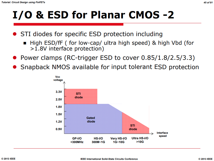
Gated diode & STI diode
"gated diode" aka. "poly bound" diode
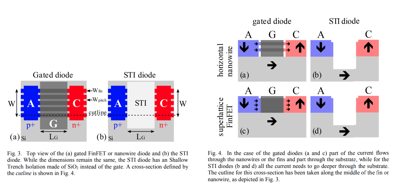
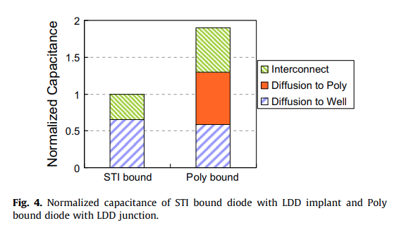
STI bound diodes typically have lower capacitance
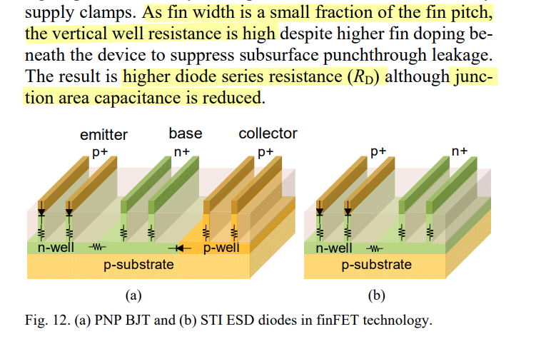
M. Simicic, G. Hellings, S. -H. Chen, N. Horiguchi and D. Linten, "ESD diodes with Si/SiGe superlattice I/O finFET architecture in a vertically stacked horizontal nanowire technology," 2018 48th European Solid-State Device Research Conference (ESSDERC), Dresden, Germany, 2018
US9653448B2. Electrostatic Discharge (ESD) Diode in FinFET Technology
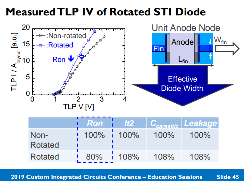
?? Rotated STI Diode
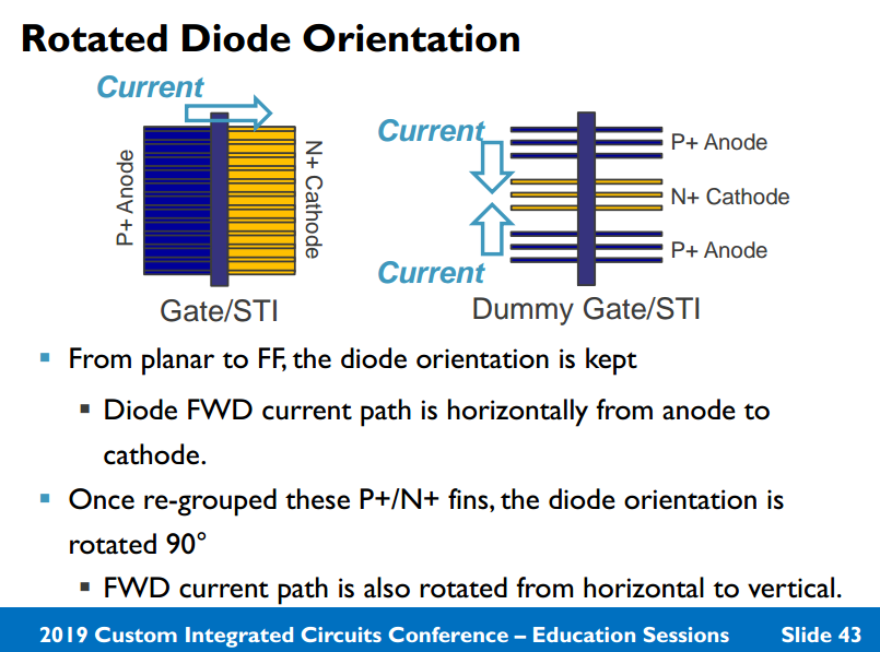
Loke, Alvin & Yang, (2018). Analog/mixed-signal design challenges in 7-nm CMOS and beyond. 10.1109/CICC.2018.8357060.
Shih-Hung Chen. CICC 2019: Designing Diode Based ESD Protection in Advanced State of the Art Technologies
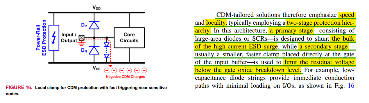
Two-Stage ESD Protection
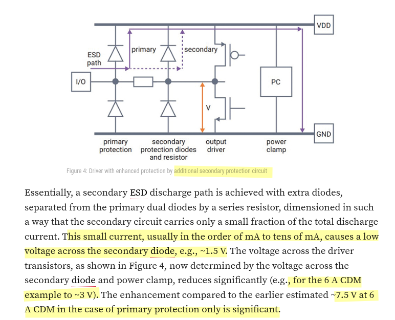
two-stage primary–secondary ESD protection
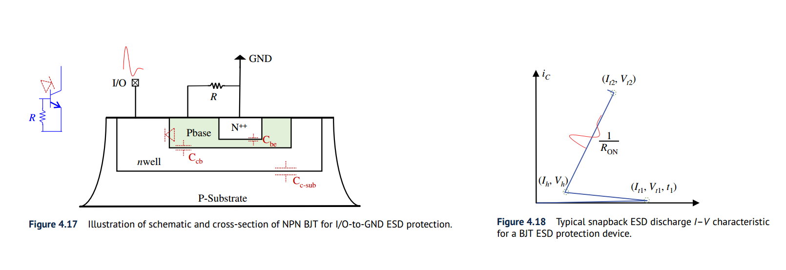
a primary ESD protection structure (ESD1), a secondary ESD protection unit (ESD2), and an isolation resistor (\(R\))
The desired specs for ESD2 is low \(V_\text{t1}\) and short \(t_1\), while that for ESD1 include low \(R_{ON}\), low \(V_\text{h}\) and high \(I_\text{t2}\)
The primary ESD1 structure is typically optimized for high ESD protection level, which however may feature a high ESD \(V_\text{t1}\), not suitable for low-voltage (LV) ICs
The secondary ESD2 unit serves as a trigger-assisting device that features a lower ESD \(V_\text{t1}\) and fast ESD triggering, which is typically weak in handling large ESD discharge currents
The isolation \(R\) has another role, which is to prevent an ESD pulse from getting into IC core (i.e., stressing the input device) directly, hence avoid possible CMOS gate breakdown
\(R\) involves a design trade-off too: large enough for fast voltage build up, but not too large to avoid adverse impact on signal propagation
The two-stage ESD protection method is re-gaining attention for CDM ESD protection because it can handle large ESD surges without overheating, while preventing CMOS gate breakdown due to the isolation R (i.e., no direct zapping on the input gate)
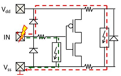
- Adding a (small) clamp behind the isolation resistance can extend the ESD design window, e.g. enabling dual diode protection for thin oxide transistors.
- ESD current through this clamp will build-up voltage across the isolation resistance, while protecting the circuit.
- The higher voltage at the IN pad will then trigger the primary protection (red current path)
Adding a (small) clamp behind the isolation resistance can extend the ESD design window, e.g. enabling dual diode protection for thin oxide transistors
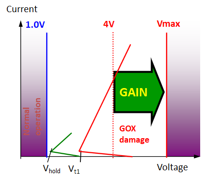
Extended ESD design window example. The failure voltage of a thin gate oxide in advanced CMOS is about 4V. The primary ESD solution (red IV curve) introduces too much voltage. Thanks to an isolation resistance between primary and secondary local clamp device (green IV curve) additional margin is created.
[https://monthly-pulse.com/2022/03/29/introduction-esd-protection-concepts-for-i-os/]
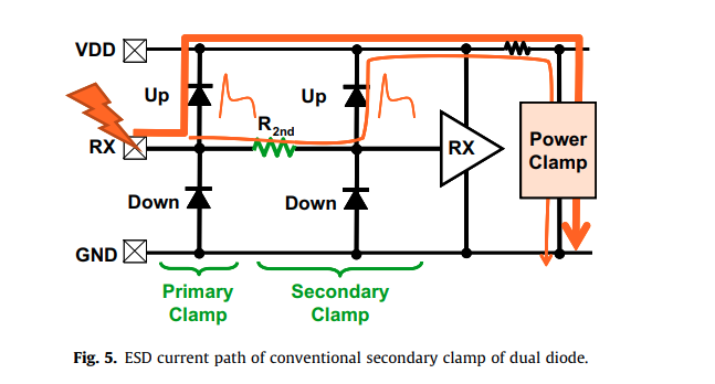
Okushima, M. and Tsuruta, J., "Secondary ESD clamp circuit for CDM protection of over 6Gbit/s SerDes application in 40nm CMOS", Microelectronics Reliability, vol. 53, no. 2, pp. 215–220, 2013 [https://sci-hub.se/https://doi.org/10.1016/j.microrel.2012.04.010]
Peter de Jong. ESD Co-Design for High-Speed SerDes in FinFET Technologies [https://incompliancemag.com/esd-co-design-for-high-speed-serdes-in-finfet-technologies/]
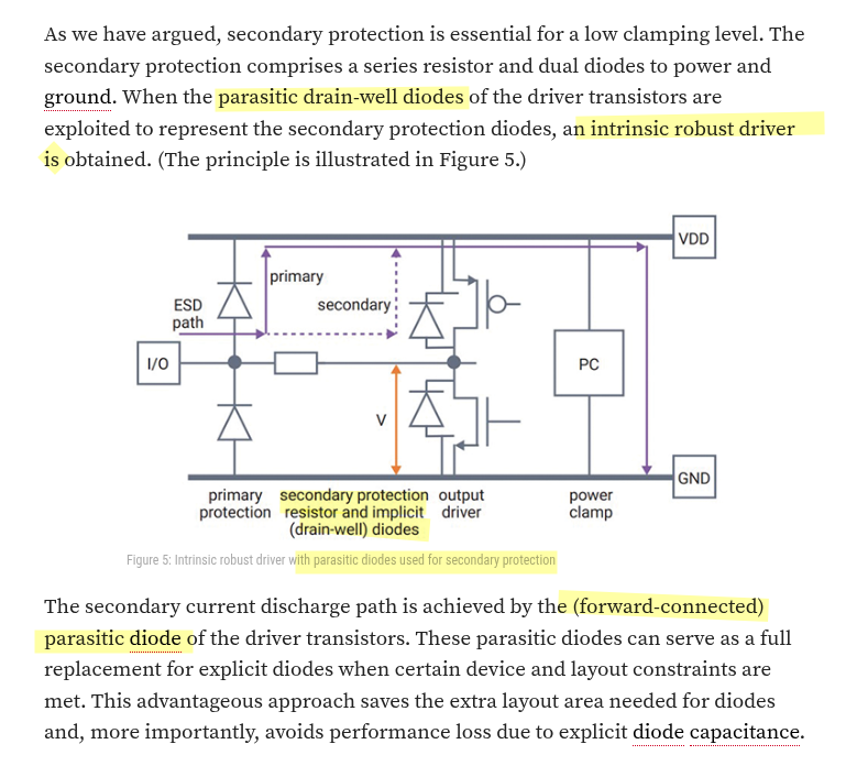
Enhanced ESD Protection for Output Driver
Intrinsic Robust Output Driver
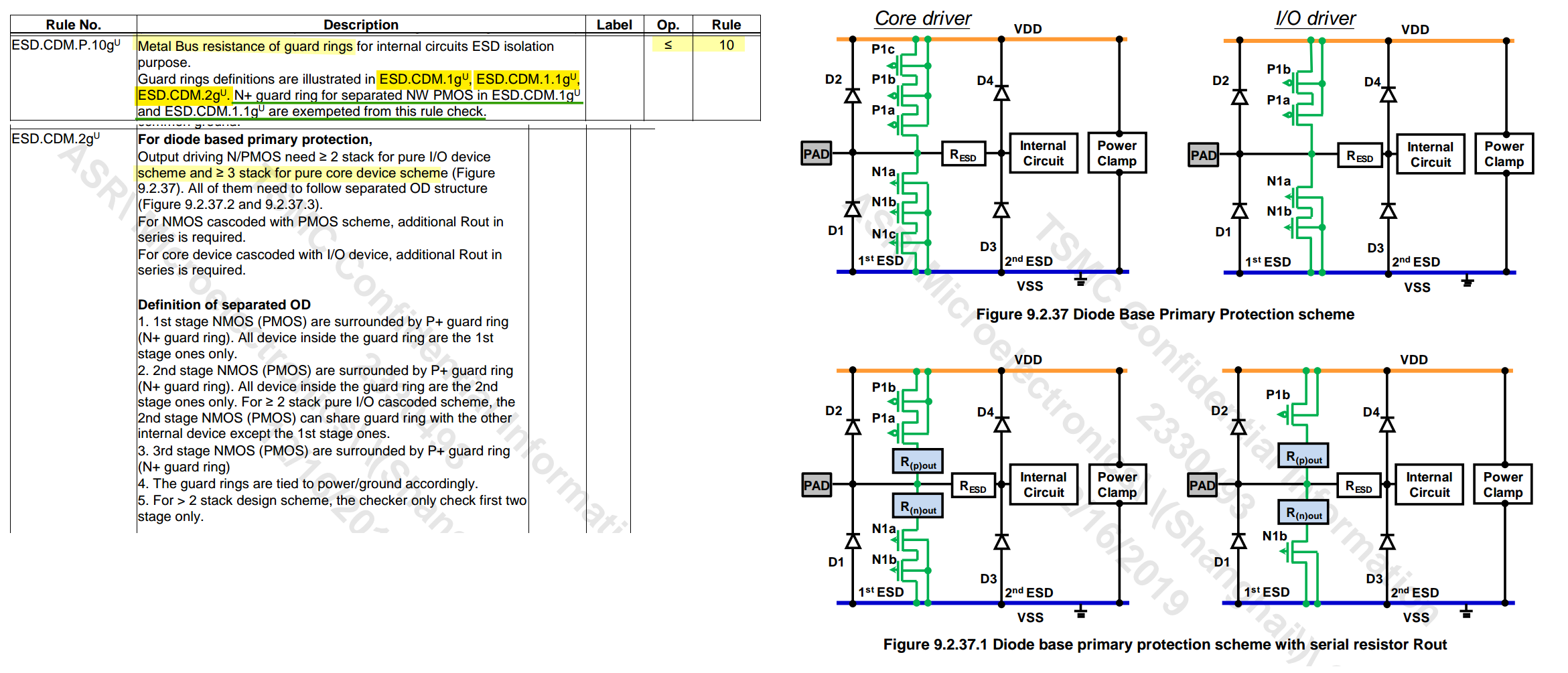
metal resistance of guard ring
Silicon Controlled Rectifiers (SCR)
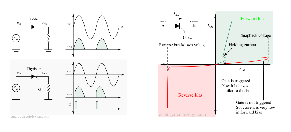
A thyristor (also known as a Silicon Controlled Rectifier or SCR) is a three-terminal semiconductor device used as an electronic switch or rectifier

To turn the thyristor on, a positive voltage pulse is applied to the gate (G) terminal. This voltage pulse needs to be of sufficient magnitude to trigger the device. When the gate is triggered, it allows a small current to flow into the base of the P-N-P transistor within the thyristor structure
[https://ec2-44-207-46-173.compute-1.amazonaws.com/thyristor/]
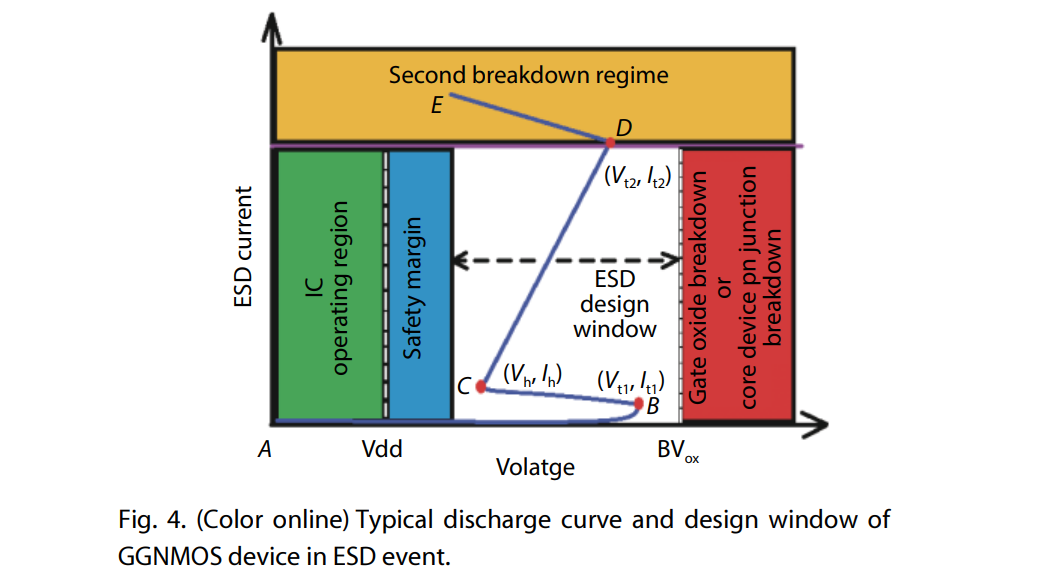
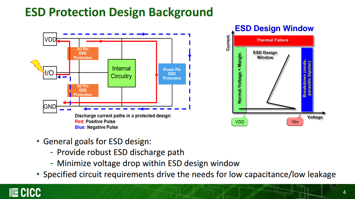
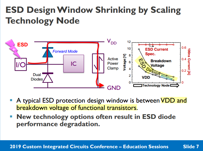
ESD design window
[https://monthly-pulse.com/2021/06/02/the-esd-design-window-concept/]
[https://www.researching.cn/ArticlePdf/m00098/2020/41/12/122403.pdf]
- Transparency
- Trigger voltage Vt1
- Holding/clamping voltage Vh
- Robustness
- failure current level It2
- Effectiveness
- maximum voltage of the clamp device: Vmax
You Li. CICC2020: ESD Protection Design Overview in Advanced SOI and Bulk FinFET Technologies
[https://picture.iczhiku.com/weixin/message1640668908028.html]
ESD工作区称为“设计窗口”
保护设备的触发电压(V t1)定义了它设计为导通的电平; 触发后的保持电压(V Hold)是指应高于施加电压的钳位电平。最后,I t2是指ESD故障电流水平。
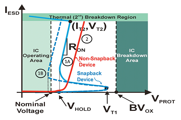
如蓝色曲线(1A或1B)所示,NMOS晶体管在触发点V t1处进入双极击穿(npn),并迅速恢复为称为V Hold的保持电压,并保护高达故障电流I ESD对应于ESD目标水平。(I t2,V t2)是指保护设备可能烧坏的散热点,因此该I t2必须大于I ESD目标电流水平(例如,目标1.5 kV HBM的电流为1 Amp)。如果保护设备的导通电阻(R on)太高,则V t2也可能达到可靠性电压极限。钳位电路必须有效触发,以使其电压累积不超过栅极氧化层击穿电压(BV ox)或晶体管击穿电压。晶体管的V Hold经过设计,使其具有一定的工作电压裕度,如曲线1A所示。相反,在具有V Hold的快速恢复装置小于工作电压(曲线1B)的情况下,存在EOS损坏的风险。
TLP/vf-TLP
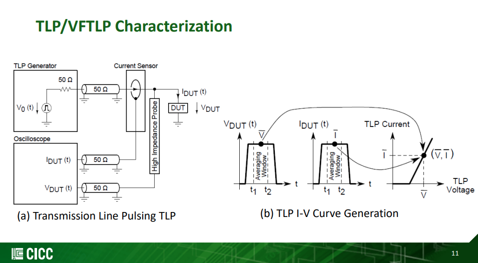
TRANSMISSION LINE PULSE TESTING: THE INDISPENSABLE TOOL FOR ESD CHARACTERIZATION OF DEVICES, CIRCUITS AND SYSTEMS [https://www.esda.org/assets/News/1708-ESD-firstDraft.pdf]
[https://monthly-pulse.com/2021/06/08/transmission-line-pulse-tlp-test-system/]
Jon Barth "TLP and VFTLP Testing of Integrated Circuit ESD Protection" [https://barthelectronics.com/wp-content/uploads/2016/09/TLP-and-VFTLP-Test-of-Integrated-Circuit-ESD-Protection.pdf]
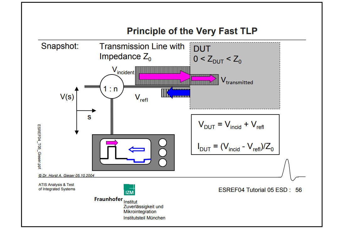
Horst A. Gieser(IZM), "ESD- Testing: HBM to very fast TLP" [https://www.thierry-lequeu.fr/data/ESREF/2004/Tut5.pdf]
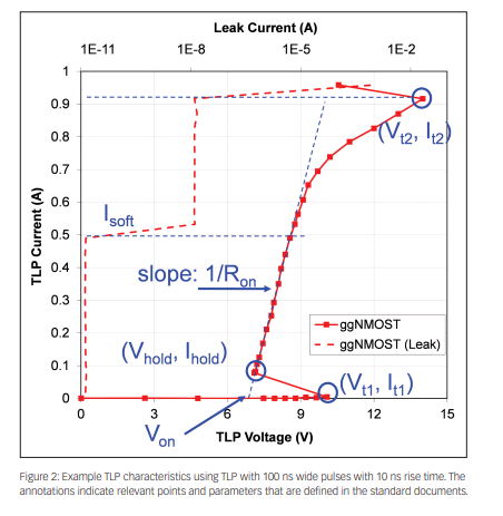
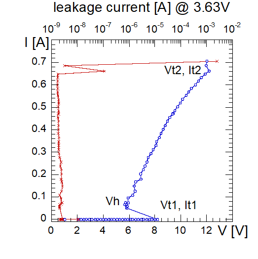
Vt1: trigger voltage
Vhold: holding voltage
soft failure current: Isoft
hard failure current: It2
TLP vs ESD
- ESD tests simulate real world events (HBM, MM, CDM)
- TLP does not simulate any real-world event
- ESD tests record failure level (Qualification)
- TLP tests record failure level and device behavior (Characterization)
TLP is not a qualification test, but a characterization method, which describes the resistance of a device for a given stimulus, aka. Device Characterization
Unlike ESD waveforms, TLP does not mimic any real world event
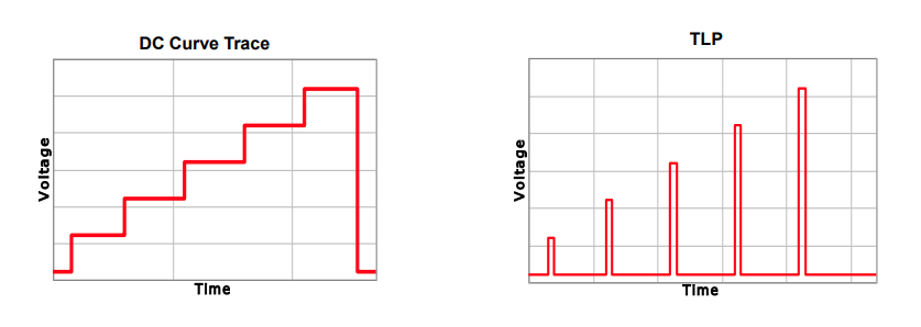
TLP and Curve Tracing
- Curve Tracing is DC; TLP is a short pulse
- Shorter pulse - Reduced duty cycle, less heating, which means higher voltage before failure
- Controlled Impedance - Allows device behavior to be observed
- Both measure resistance of device with increasing voltage
Device Characterization with TLP
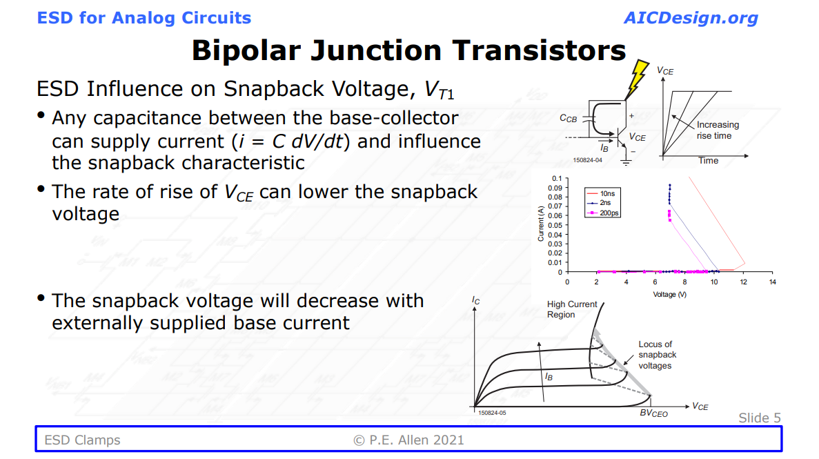
- Turn-on time
- Snapback voltage
- Performance changes with rise time
VF-TLP and CDM differences
Question:
How well will VF-TLP results predict CDM testing performance?
Answer:
VF-TLP can be a guide to CDM failure levels, and provide a lot of understanding of a circuit's operation during CDM stressing, but simple correlations between VF-TLP failure current level and CDM withstand voltage levels are difficult to establish.
I.V and Leakage Evolution Plots
DC leakage current data combined with the I-V data provides electrical indications of where damage begins, and how rapidly it can evolve from soft to hard failures
Henry, Leo & Barth, Jon & Richner, John & Verhaege, Koen. (2000). Transmission Line Pulse Testing of the ESD Protection Structures in ICs - A Failure Analyst's Perspective. 203-213. 10.31399/asm.cp.istfa2000p0203. [https://barthelectronics.com/pdf_files/2000%20ISTFA%20TLP%20Testing%20of%20the%20ESD%20Protection%20Structure.pdf]
Henry, L.G. & Barth, Jon & Verhaege, K. & Richner, J.. (2001). Transmission-line pulse ESD testing of ICs: A new beginning. Compliance Engineering. 18. 46+53. [https://barthelectronics.com/pdf_files/CE%20TLP%20Article%20March-April%202001.pdf]
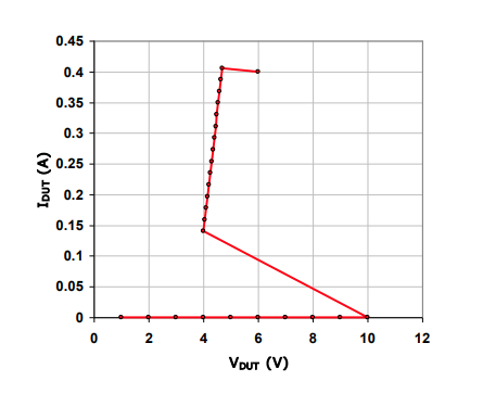
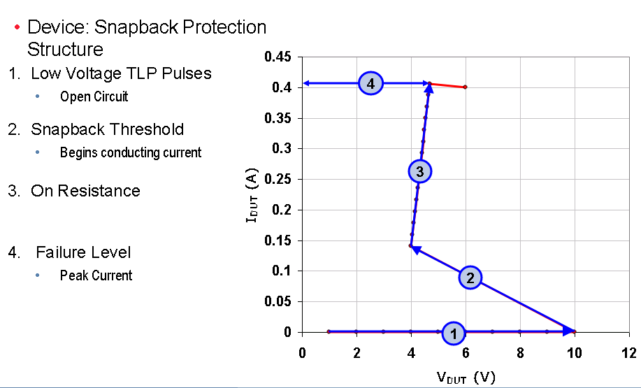
Snapback devices
Lesson 2 - ESD Clamps [https://aicdesign.org/wp-content/uploads/2021/05/Lesson02_ESD_Clamps210315.pdf]
Introduction of Transmission Line Pulse (TLP) Testing for ESD Analysis - Device Level [https://www.esdemc.com/public/docs/TechnicalSlides/ESDEMC_TS001.pdf]
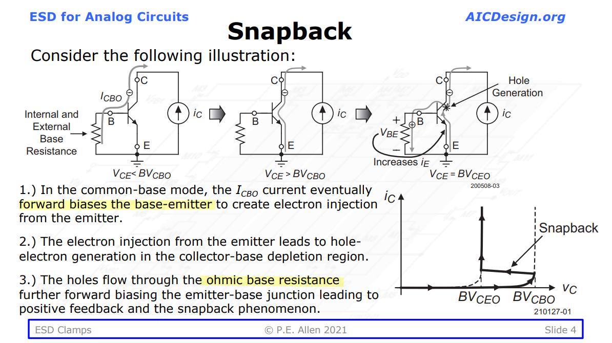
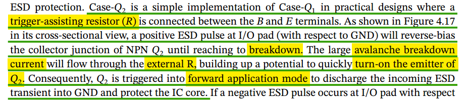
BJT
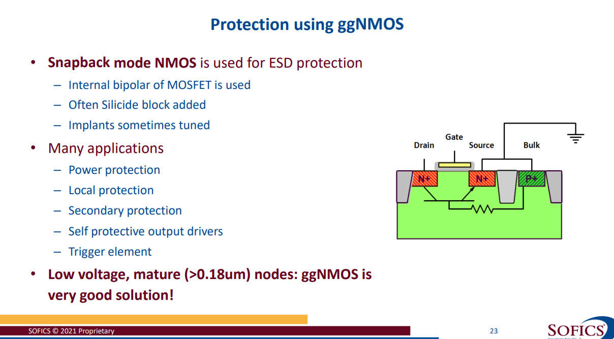
Grounded-gate NMOS (ggNMOS)
[https://monthly-pulse.com/2022/02/02/time-to-say-farewell-to-the-snapback-ggnmos-for-esd-protection/]
[https://monthly-pulse.com/2023/01/26/ggnmos-grounded-gated-nmos/]
snapback ggNMOS for ESD protection
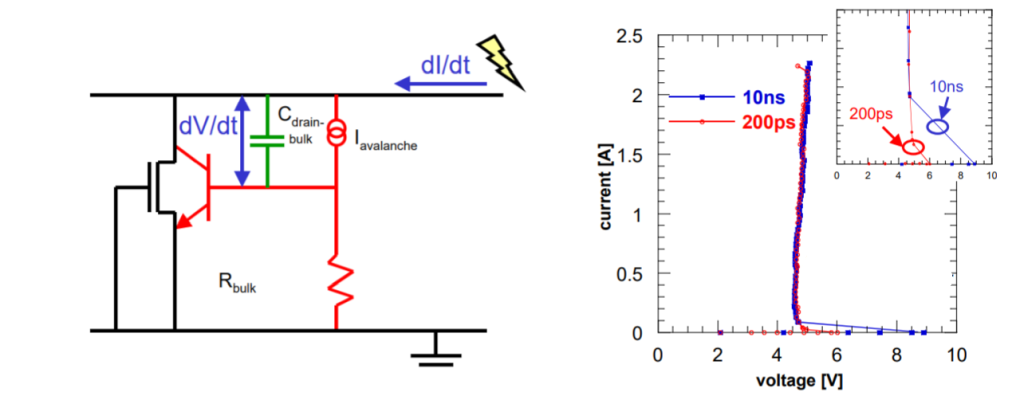
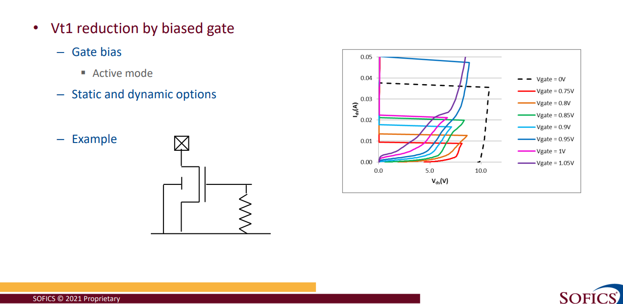
Influence of the pulse rise time on ggNMOS. (left side) A fast ESD pulse can couple the bulk of the NMOS to a higher potential for a short period, reducing the trigger voltage. (right side) A clear Vt1 reduction is visible, while the remaining part of the IV curve remains the same.
[https://picture.iczhiku.com/weixin/message1588643699565.html]
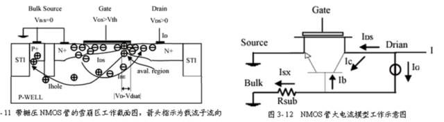
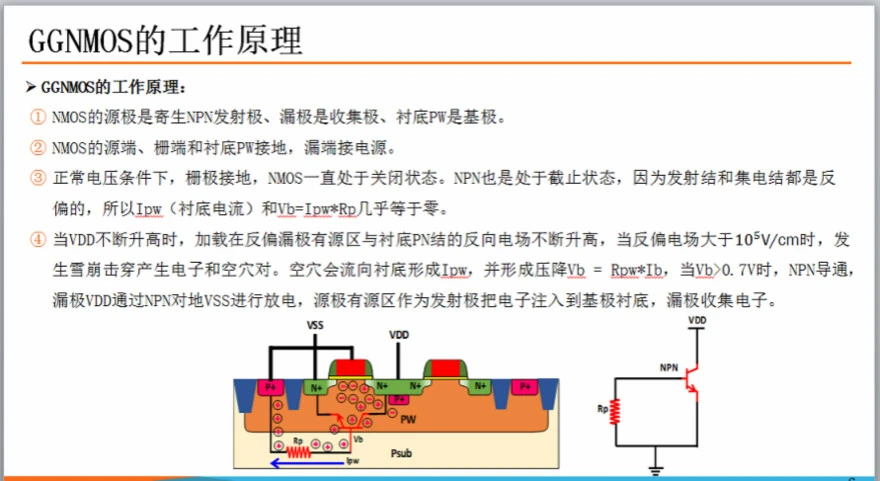
一般都是把Gate/Source/Bulk短接在一起,把Drain结在I/O端承受ESD的浪涌(surge)电压,NMOS称之为GGNMOS (Gate-Grounded NMOS)PMOS称之为GDPMOS (Gate-to-Drain PMOS)。以NMOS为例,原理都是Gate关闭状态,Source/Bulk的PN结本来是短接0偏的,当I/O端有大电压时,则Drain/Bulk PN结雪崩击穿,瞬间bulk有大电流与衬底电阻形成压差导致Bulk/Source的PN正偏,所以这个MOS的寄生横向NPN管进入放大区(发射结正偏,集电结反偏),所以呈现特性,起到保护作用。PMOS同理推导。
Trigger电压/Hold电压: Trigger电压当然就是之前将的的第一个拐点(Knee-point),寄生BJT的击穿电压,而且要介于BVCEO与BVCBO之间。而Hold电压就是要维持持续ON,但是又不能进入栅锁(Latch-up)状态,否则就进入二次击穿(热击穿)而损坏了。还有个概念就是二次击穿电流,就是进入Latch-up之后I^2*R热量骤增导致硅融化了,而这个就是要限流,可以通过控制W/L,或者增加一个限流高阻, 最简单最常用的方法是拉大Drain的距离/拉大SAB的距离(ESD rule的普遍做法)。
PN结的击穿分两种,分别是电击穿和热击穿,电击穿指的是雪崩击穿, Avalanche Breakdown (低浓度)和齐纳击穿(高浓度),而这个电击穿主要是载流子碰撞电离产生新的电子-空穴对(electron-hole),所以它是可恢复的。但是热击穿是不可恢复的,因为热量聚集导致硅(Si)被熔融烧毁了。所以我们需要控制在导通的瞬间控制电流,一般会在保护二极管再串联一个高电阻,
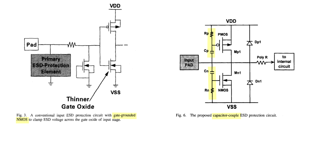
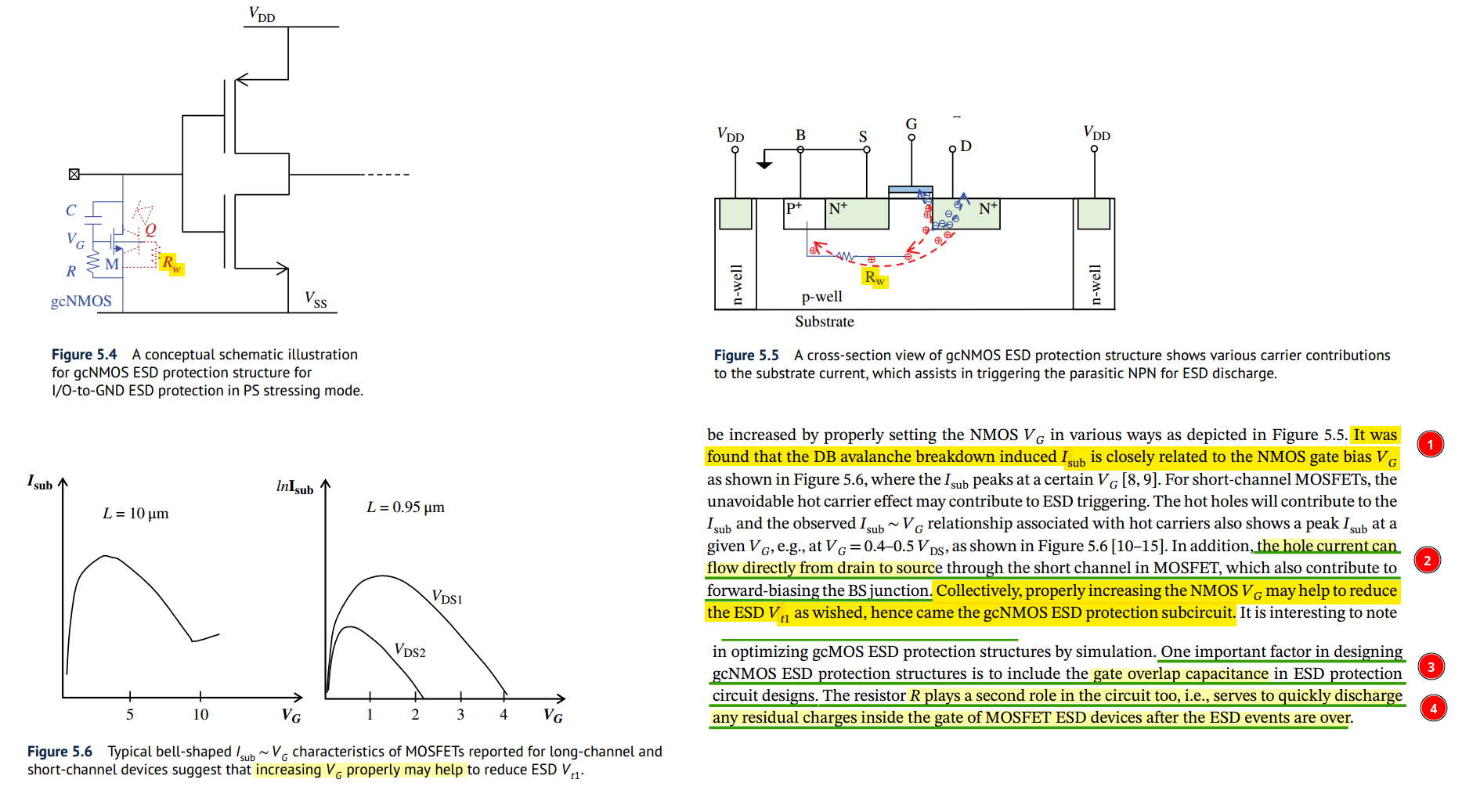
Gate-coupled NMOS (gcNMOS)
Ming-Dou Ker, Chung-Yu Wu, Tao Cheng and Hun-Hsien Chang, "Capacitor-couple ESD protection circuit for deep-submicron low-voltage CMOS ASIC," in IEEE Transactions on Very Large Scale Integration (VLSI) Systems, vol. 4, no. 3, pp. 307-321, Sept. 1996 [https://ir.lib.nycu.edu.tw/bitstream/11536/1053/1/A1996VE01800002.pdf]
Gate-coupled NMOS (gcNMOS) was proposed to effectively reduce the \(V_\text{t1}\)
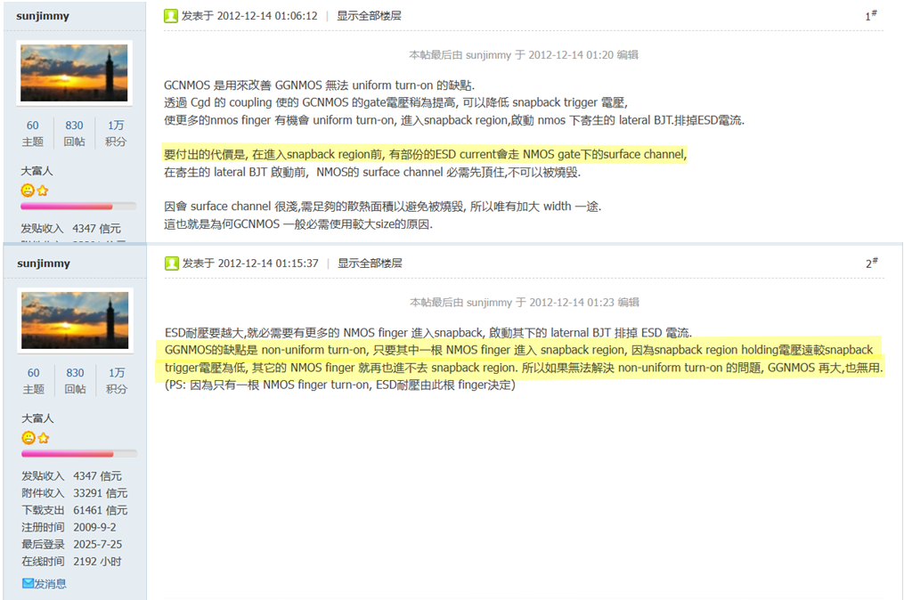
[https://bbs.eetop.cn/forum.php?mod=redirect&goto=findpost&ptid=353178&pid=7305079]
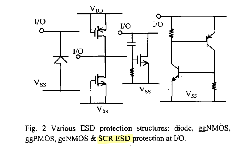
SCR (thyristor)
Guang Chen, Haigang Feng and A. Wang, "A systematic study of ESD protection structures for RF ICs," IEEE Radio Frequency Integrated Circuits (RFIC) Symposium, 2003, Philadelphia, PA, USA, 2003 [https://sci-hub.se/10.1109/RFIC.2003.1213959]
[https://www.sharecourse.net/sharecourse/upload/course/180/c574580760de44d2c6fb66d8be4c6d4a.pdf]
Safe operating area (SOA)
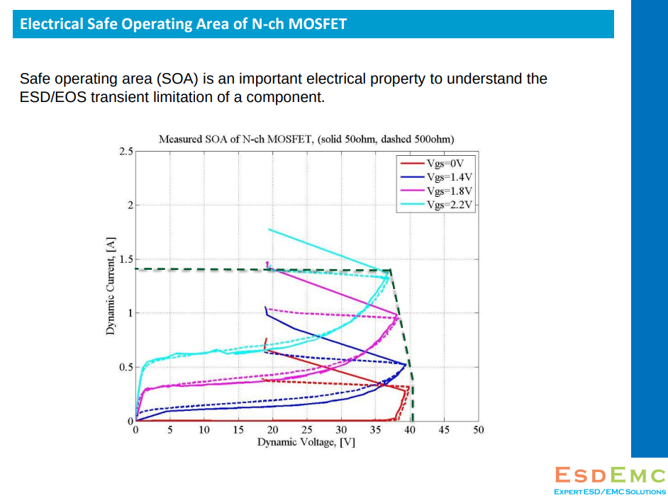
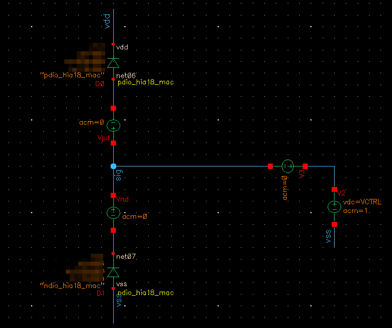
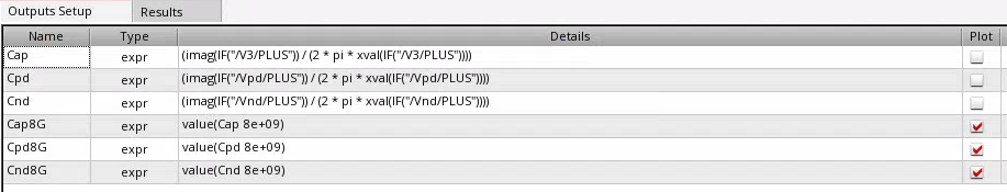
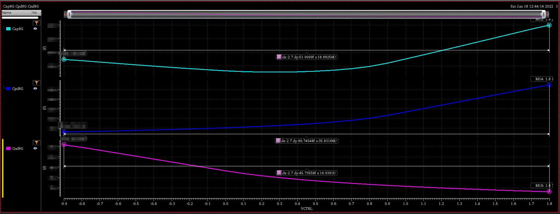
high current diode (HIA)
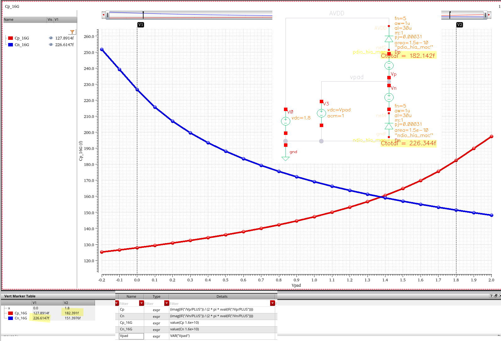
both diode are reverse-biased in normal operation, the PN Junction capacitance is proportional to forward-bias voltage
| Device | |
|---|---|
| ndio_mac | N+/P-well Diode |
| pdio_mac | P+/N-well Diode |
| ndio_18_mac | 1.8V N+/P-well Diode |
| pdio_18_mac | 1.8V P+/N-well Diode |
| ndio_hia18_mac | N-HIA Diode |
| pdio_hia18_mac | P-HIA Diode |
| ndio_gated18_mac | Thick Oxide N-Gated Diode |
| pdio_gated18_mac | Thick Oxide P-Gated Diode |
HIA_DIO can be used for logic or high speed circuits ESD protection
HIA: high current application purpose (High Amp)
There is no process difference between HIA_DIO and regular diode
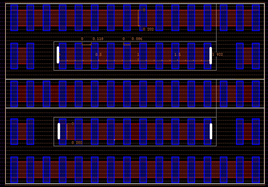
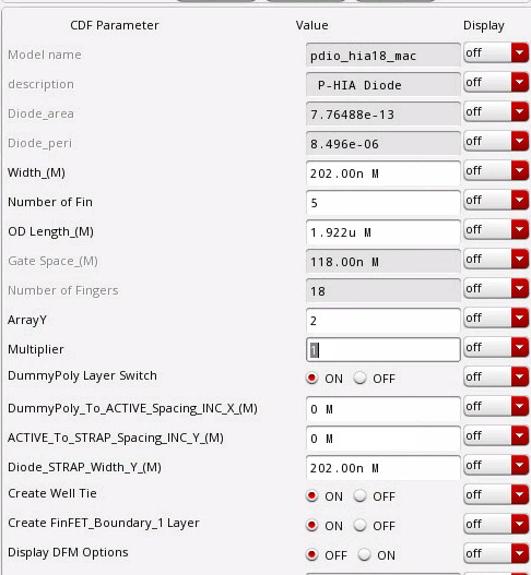
| width (W) | 2.020E-07 |
|---|---|
| Length (L) | 1.922E-06 |
| ArrayY (Ny) | 2 |
| Perimeter (Ny*2*(W+L)) | 8.496E-06 |
| Area (Ny*W*L) | 7.76488E-13 |
diode is drain/source originated, which is different from MOS (Gate originated)
The perimeter of diode in DRC is different from that in PERC deck, where PERC excludes the the left and right edge of OD
g after the rule numbers: DFM recommendations and guidelines
U: the rule is not checked by the DRC
I-V curve
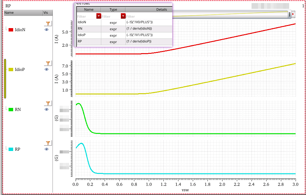
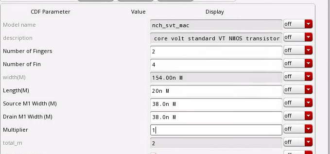
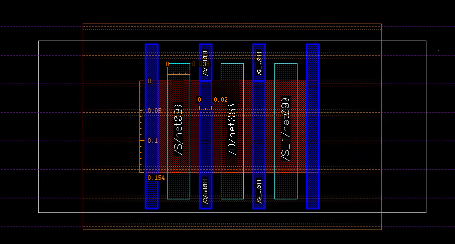
MOS
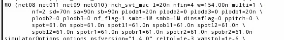
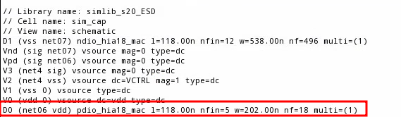
lin netlist has different definition for MOS and diode.MOS: length of channel
diode: Gate space
HIA = High Amp
lateral diode: perimeter is key DRC rule for ESD diode
HIA diode process is same with regular junction diode
EOS
[https://picture.iczhiku.com/weixin/message1640668908028.html]
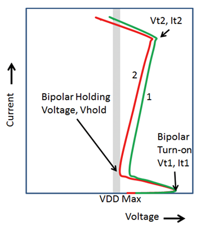
尽管通常ESD保护的设计并非旨在防止EOS事件,但根据特定的应用和操作,上述器件的ESD保护的IC 设计风格确实可以影响EOS损坏导致的故障率。环境。图2说明了两个不同的骤回设备,其中设备1与设备2的设计相比相对安全。设备2的EOS风险增加是由于V Hold参数低于最大允许VDD。
CMOS集成电路闩锁效应 - 摘录
CMOS闩锁效应的发展
闩锁效应是以体CMOS工艺为基础的集成电路特有的现象,无论是一般的常规体CMOS工艺集成电路,还是从CMOS工艺衍生出来的BiCMO、BCD和HV-CMOS等,都会发生闩锁效应。
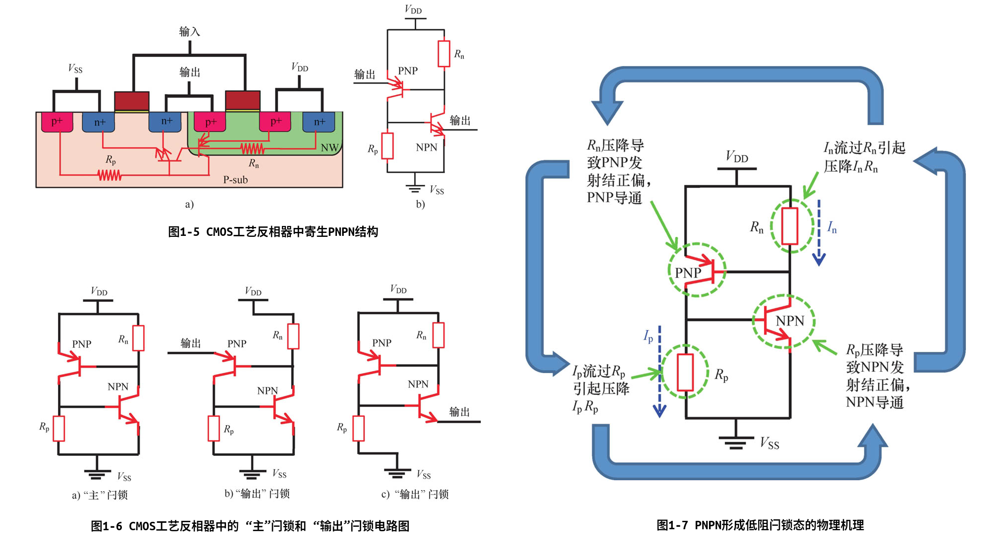
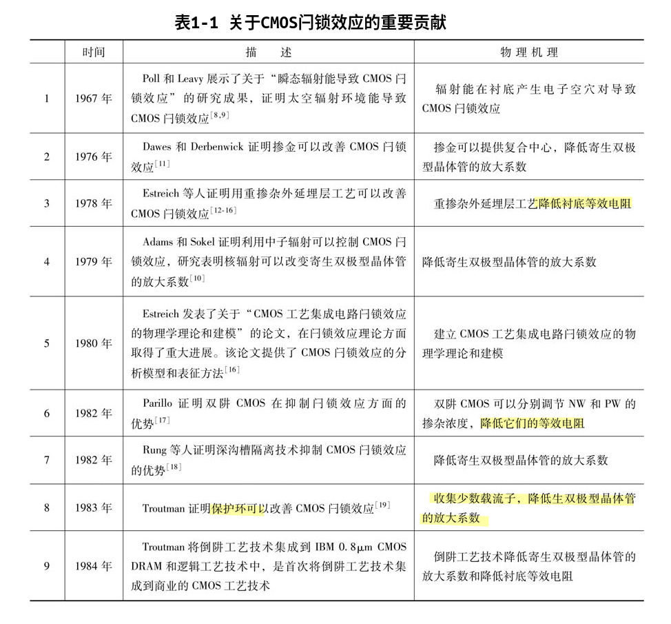
- 降低寄生BJT的放大系数
- 降低衬底等效电阻
双极型晶体管
双极型晶体管的四种工作模式下集电结和发射结外加偏置电压
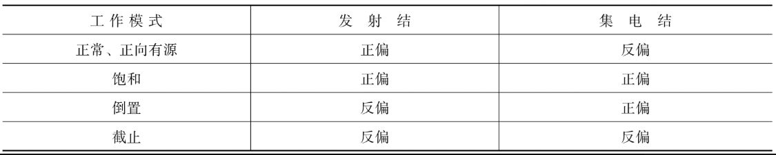
1)正向有源:双极型晶体管的发射结正偏和集电结反偏。工作在正向有源区的双极型晶体管具有电流放大功能,它的放大系数是\(\beta\),\(\beta\)是集电极电流与基极电流的比,\(\beta\)是一个非常关键的参数,通常双极型晶体管设计和制造工艺参数的变动都是为了获得足够大的\(\beta\)。正向有源是一种常用的工作区
2)饱和:双极型晶体管的发射结和集电结都正偏,它相当于两个并联的二极管。
3)倒置:双极型晶体管发射结反偏和集电结正偏。与正向有源相比,它们的角色倒置了。工作在倒置区的双极型晶体管也具有电流放大功能,不过其放大系数会比正向有源小几倍。实际应用中也很少会把双极型晶体管偏置在倒置区。
4)截止:双极型晶体管的发射结和集电结都反偏,其漏电流非常微弱,就像开路的开关
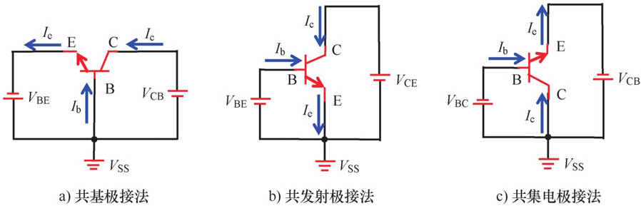
根据双极型晶体管的电极被输入和输出共用的情况,可以把双极型晶体管分为三种电路连接方式
双极型晶体管的击穿电压
双极型晶体管两个PN结的反向击穿电压有以下三种:
第一种是发射极开路时的BVCBO; 第二种是集电极开路时的BVEBO; 第三种是基极开路时的BVCEO。
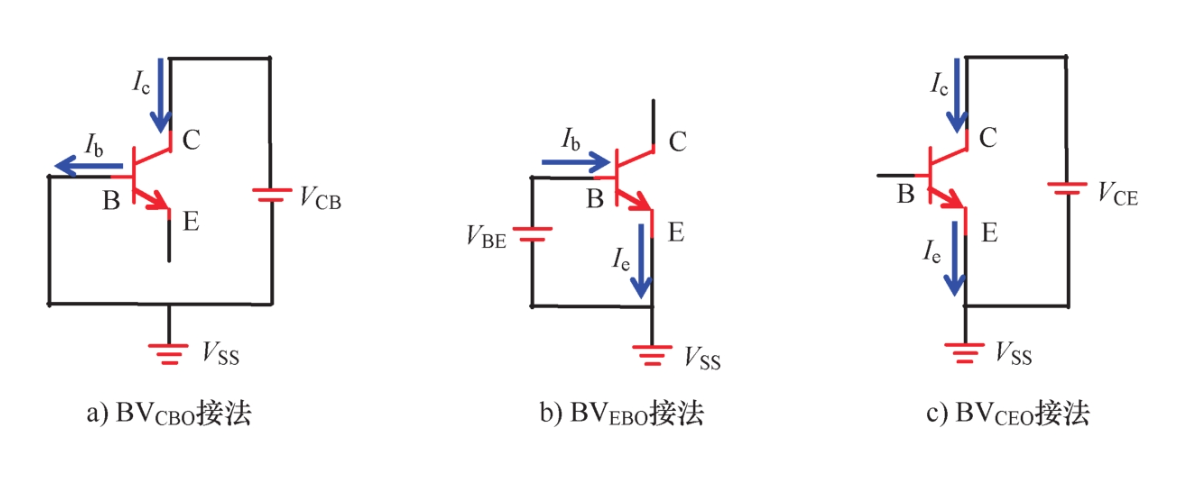
这三个击穿电压的关系如下:BVCBO>BVCEO>BVEBO
NPN闩锁效应
在CMOS集成电路中,不仅寄生的PNPN结构会发生闩锁效应,单个NMOS自身寄生NPN也会发生闩锁效应
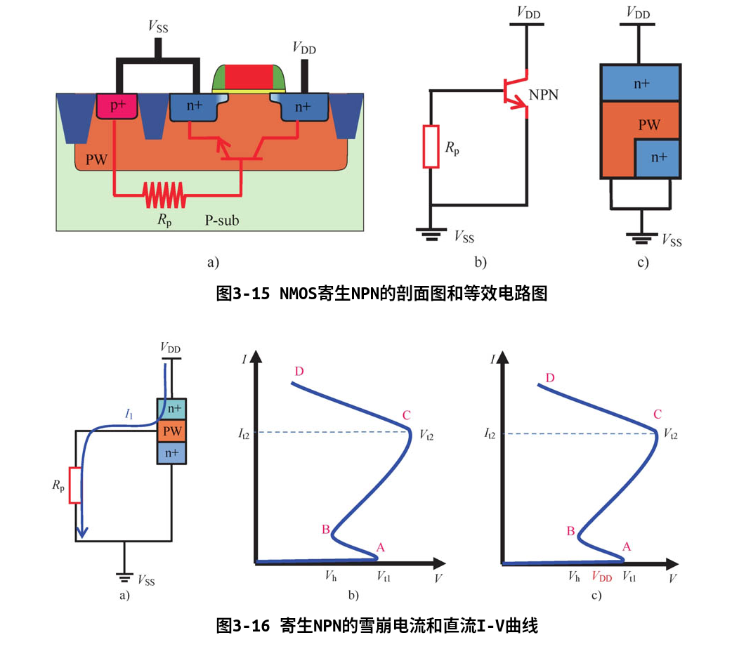
与PNPN类似,从寄生NPN I-V曲线可以看出,有两种方式可以使寄生NPN工作状态进入BC段的闩锁态:
- 第一种是出现瞬态激励电压大于等于Vt1,从而产生雪崩击穿电流,使寄生NPN进入闩锁态,这种方式称为电压触发;
- 第二种是出现瞬态激励电流,该电流大于等于B点对应的电流Ih,使寄生NPN进入闩锁态,这种方式称为电流触发。
Reference
Wang, Albert. Practical ESD Protection Design. John Wiley & Sons, 2021.
温德通. CMOS集成电路闩锁效应. 机械工业出版社, 2020
ANSI/ESDA/JEDEC JS-002-2022: ESDA/JEDEC Joint Standard For Electrostatic Discharge Sensitivity Testing Charged Device Model (CDM) Device Level
ESDA/JEDEC JTR002-01-22: For the User Guide of ANSI/ESDA/JEDEC JS-002 Charged Device Model Testing of Integrated Circuits
JESD22-C101E: Field-Induced Charged-Device Model Test Method for Electrostatic Discharge-Withstand Thresholds of Microelectronic Components
C. -Y. Lin and M. -D. Ker, "ESD Protection Design: Fundamentals and Advanced Strategies," in IEEE Open Journal of the Solid-State Circuits Society, vol. 6, pp. 61-76, 2026 [pdf]
M. Di, H. Wang, F. Zhang, C. Li, Z. Pan and A. Wang, "Does CDM ESD Protection Really Work?," 2019 IEEE Workshop on Microelectronics and Electron Devices (WMED), Boise, ID, USA, 2019 [https://sci-hub.se/10.1109/WMED.2019.8714145]
M. Di, C. Li, Z. Pan and A. Wang, "Pad-Based CDM ESD Protection Methods Are Faulty," in IEEE Journal of the Electron Devices Society, vol. 8, pp. 1297-1304, 2020 [pdf]
Introduction to Transmission Line Pulse (TLP), URL: https://tools.thermofisher.com/content/sfs/brochures/TLP%20Presentation%20May%202009.pdf
VF-TLP and CDM differences, URL: https://www.grundtech.com/app-note-vf-tlp-cdm-differences
ESD-Testing: HBM to very fast TLP URL: https://www.thierry-lequeu.fr/data/ESREF/2004/Tut5.pdf
S. Kim et al., "Technology Scaling of ESD Devices in State of the Art FinFET Technologies," 2020 IEEE Custom Integrated Circuits Conference (CICC), 2020, pp. 1-6, doi: 10.1109/CICC48029.2020.9075899.
KOEN DECOCK IEEE-SSCSLEUVEN "ON-CHIP ESD PROTECTION: BASIC CONCEPTS AND ADVANCED APPLICATIONS" [https://monthly-pulse.com/wp-content/uploads/2021/11/2021-11-sofics_presentation_ieee_final.pdf]
Yuanzhong Zhou, D. Connerney, R. Carroll and T. Luk, "Modeling MOS snapback for circuit-level ESD simulation using BSIM3 and VBIC models," Sixth international symposium on quality electronic design (isqed'05), 2005, pp. 476-481, doi: 10.1109/ISQED.2005.81.
Charged Device Model (CDM) Qualification Issues - Expanded [https://www.jedec.org/sites/default/files/IndustryCouncil_CDM_October2021_JEDECversion_September2022_rev1.pdf]
Wang, Albert ZH. On-chip ESD protection for integrated circuits: an IC design perspective. Vol. 663. Springer Science & Business Media, 2002.
Ker, Ming-Dou, and Sheng-Fu Hsu. Transient-induced latchup in CMOS integrated circuits. John Wiley & Sons, 2009. [https://picture.iczhiku.com/resource/eetop/wyiGjQaHOgrYFcxB.pdf]
Milin Zhang, "Low Power Circuit Design Using Advanced CMOS Technology" River Publishers 2018
Barry Fernelius, Evans Analytical Group. Latch-up Testing [https://site.ieee.org/ocs-cpmt/files/2013/06/Latch-up_at_EAG_IEEE_September_2013.pdf]
M. -D. Ker and Z. -H. Jiang, "Overview on Latch-Up Prevention in CMOS Integrated Circuits by Circuit Solutions," in IEEE Journal of the Electron Devices Society, vol. 11, pp. 141-152, 2023 [https://ieeexplore.ieee.org/stamp/stamp.jsp?arnumber=9998049]
Shih-Hung Chen. CICC 2019. ES2-4 "ESD Challenges in Advanced FinFET & GAA Nanowire CMOS technologies"
Y. Li, M. Miao and R. Gauthier, "ESD Protection Design Overview in Advanced SOI and Bulk FinFET Technologies," 2020 IEEE Custom Integrated Circuits Conference (CICC), Boston, MA, USA, 2020
S. Kim et al., "Technology Scaling of ESD Devices in State of the Art FinFET Technologies," 2020 IEEE Custom Integrated Circuits Conference (CICC), Boston, MA, USA, 2020