Voltage-Mode Driver Equalization
CML vs. SST based driver
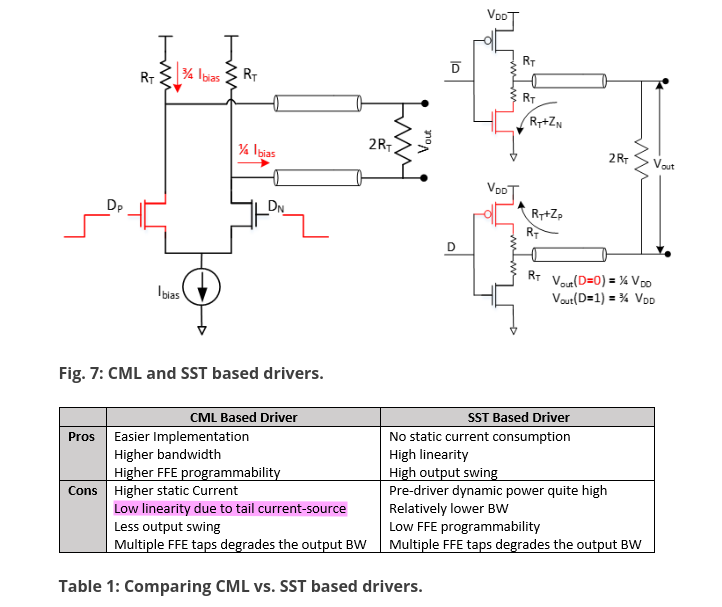
Design Challenges Of High-Speed Wireline Transmitters [https://semiengineering.com/design-challenges-of-high-speed-wireline-transmitters/]
SST Driver
sharing termination in SST transmitter

Sharing termination keep a constant current through leg, which improve TX speed in this way. On the other hand, the sharing termination facilitate drain/source sharing technique in layout.
pull-up and pull-down resistor
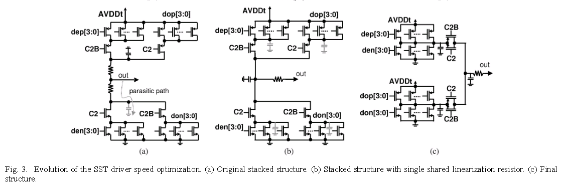
Original stacked structure
Pro's:
smaller static current when both pull up and pull down path is on
Con's:
slowly switching due to parasitic capacitance behind pull-up and pull-down resistor
with single shared linearization resistor
Pro's:
The parasitic capacitance behind the resistor still exists but is now always driven high or low actively
Con's:
more static current
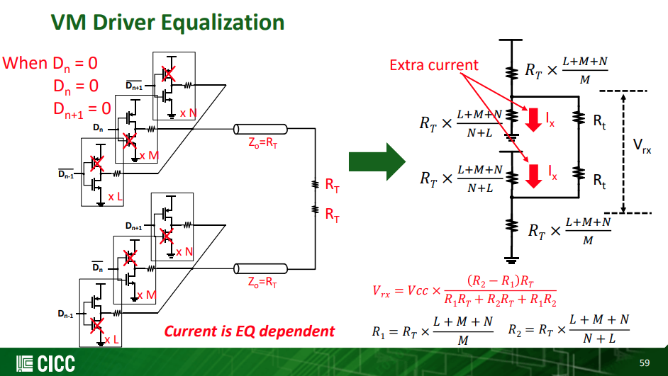
VM Driver Equalization - differential ended termination
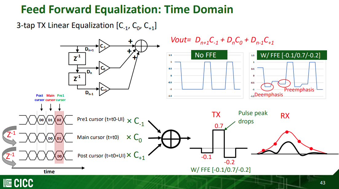
\[ V_o = D_{n+1}C_{-1}+D_nC_0+D_{n-1}C_{+1} \]
where \(D_n \in \{-1, 1\}\)
 \[
V_{\text{rx}} = V_{\text{dd}} \frac{(R_2-R_1)R_T}{R_1R_T+R_2R_T+R_1R_2}
\] With \(R_u=(L+M+N)R_T\)
\[
V_{\text{rx}} = V_{\text{dd}} \frac{(R_2-R_1)R_T}{R_1R_T+R_2R_T+R_1R_2}
\] With \(R_u=(L+M+N)R_T\)
Normalize above equation, obtain \[ V_{\text{rx,norm}} = \frac{(R_2-R_1)R_T}{R_1R_T+R_2R_T+R_1R_2} \]
| \(D_{n-1}\) | \(D_{n}\) | \(D_{n+1}\) | |
|---|---|---|---|
| \(C_{-1}\) | 1 | -1 | -1 |
| \(C_0\) | -1 | 1 | -1 |
| \(C_{+1}\) | -1 | -1 | 1 |
Where precursor \(R_L = L\times R_T\), main cursor \(R_M = M\times R_T\) and post cursor \(R_N = N\times R_T\)
Equation-1
\(D_{n-1}D_nD_{n+1}=1,-1,-1\)

\[\begin{align} R_1 &= R_N \\ &= \frac{R_u}{N} \\ R_2 &= R_L\parallel R_M \\ &= \frac{R_u}{L+M} \end{align}\]
We obtain \[ V_{L}= \frac{1}{2}\cdot\frac{N-(L+M)}{L+M+N} \]
Equation-2
\(D_{n-1}D_nD_{n+1}=-1,1,-1\)

with \(R_1=R_T\) and \(R_2=+\infty\), we obtain \[ V_M = \frac{1}{2} \]
Equation-3
\(D_{n-1}D_nD_{n+1}=-1,-1,1\)
\[\begin{align} R_1 &= R_L \\ &= \frac{R_u}{L} \\ R_2 &= R_N\parallel R_M \\ &= \frac{R_u}{N+M} \end{align}\]
We obtain \[ V_N = \frac{1}{2}\cdot\frac{L-(N+M)}{L+M+N} \]
Obtain FIR coefficients
We define \[\begin{align} l &= \frac{L}{L+M+N} \\ m &= \frac{M}{L+M+N} \\ n &= \frac{N}{L+M+N} \end{align}\]
where \(l+m+n=1\)
Due to Eq1 ~ Eq3 \[ \left\{ \begin{array}{cl} C_{-1}-C_0-C_1 & = \frac{1}{2}(n-l-m) \\ -C_{-1}+C_0-C_1 & = \frac{1}{2} \\ -C_{-1}-C_0+C_1 & = \frac{1}{2}(l-n-m) \end{array} \right. \] After scaling, we get \[ \left\{ \begin{array}{cl} C_{-1}-C_0-C_1 & = -l-m+n \\ -C_{-1}+C_0-C_1 & = l+m+n \\ -C_{-1}-C_0+C_1 & = l-m-n \end{array} \right. \] Then, the relationship between FIR coefficients and legs is clear, i.e. \[\begin{align} C_{-1} &= -\frac{L}{L+M+N} \\ C_{0} &= \frac{M}{L+M+N} \\ C_{1} &= -\frac{N}{L+M+N} \end{align}\]
For example, \(C_{-1}=-0.1\), \(C_0=0.7\) and \(C_1=-0.2\) \[
H(z) = -0.1+0.7z^{-1}-0.2z^{-2}
\] 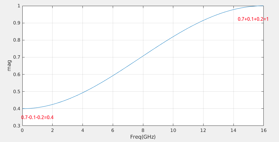
1 | w = [-0.1, 0.7, -0.2]; |
VM Driver Equalization - single ended termination
Equation-1

\[\begin{align} V_{\text{rxp}} &= \frac{1}{2} \cdot \frac{N}{L+M+N} \\ V_{\text{rxm}} &= \frac{1}{2} \cdot \frac{L+M}{L+M+N} \end{align}\] So \[ V_{L}= \frac{1}{2}\cdot\frac{N-(L+M)}{L+M+N} \] which is same with differential ended termination
Equation-2

\[\begin{align} V_{\text{rxp}} &= \frac{1}{2} \\ V_{\text{rxm}} &= 0 \end{align}\] So \[ V_{M}= \frac{1}{2} \] which is same with differential ended termination
Equation-3
\[ V_{N}= \frac{1}{2}\cdot\frac{L-(N+M)}{L+M+N} \]
Obtain FIR coefficients
Same with differential ended termination driver.
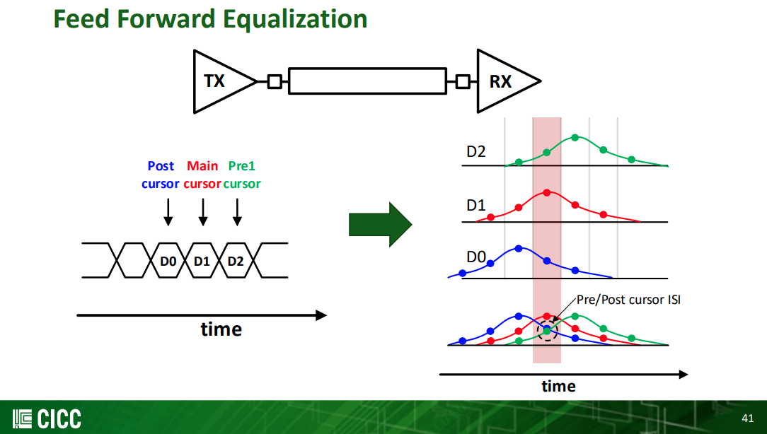
Basic Feed Forward Equalization Theory
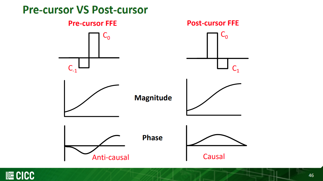
Pre-cursor FFE can compensate phase distortion through the channel
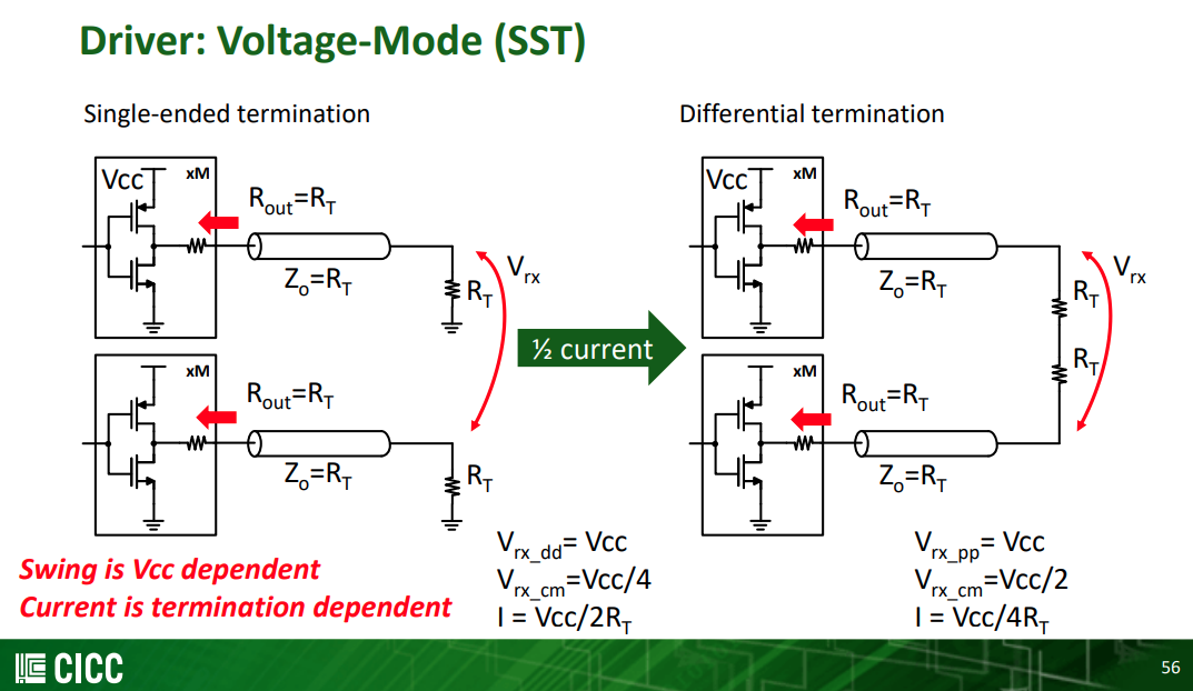
Single-ended termination
Differential termination
reference
J. F. Bulzacchelli et al., "A 28-Gb/s 4-Tap FFE/15-Tap DFE Serial Link Transceiver in 32-nm SOI CMOS Technology," in IEEE Journal of Solid-State Circuits, vol. 47, no. 12, pp. 3232-3248, Dec. 2012, doi: 10.1109/JSSC.2012.2216414.
Jhwan Kim, CICC 2022, ES4-4: Transmitter Design for High-speed Serial Data Communications
Design Challenges Of High-Speed Wireline Transmitters [https://semiengineering.com/design-challenges-of-high-speed-wireline-transmitters/]