RC corner
Traditional RC Corners
Metal width variation (\(\Delta W\)), Metal thickness variation (\(\Delta T\)), IMD thickness variation (\(\Delta H\))
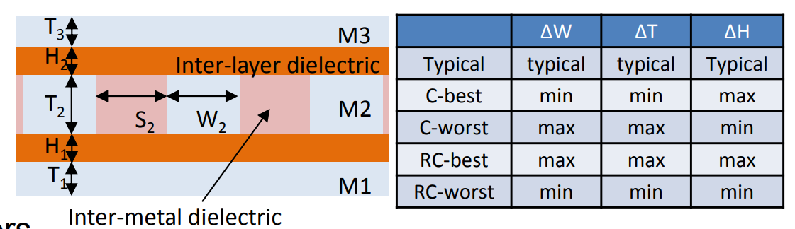
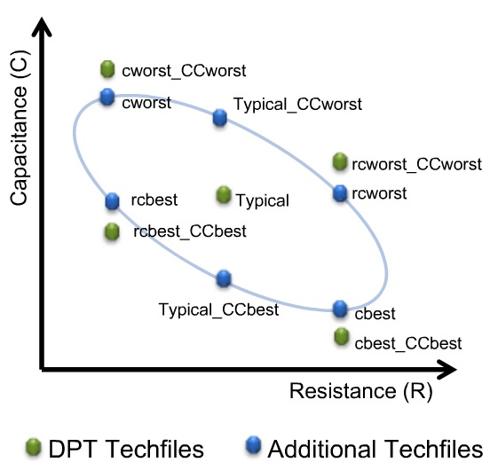
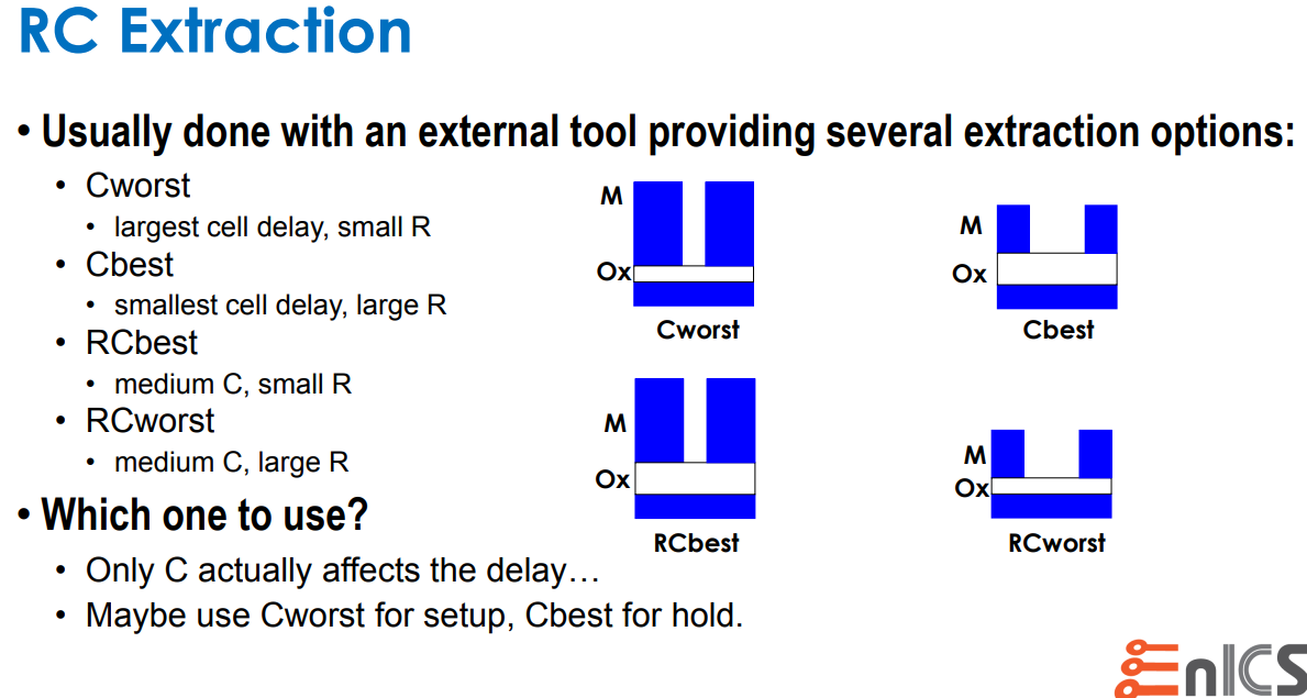
Capacitance Dominant: C-best, C-worst
Resistance Dominant: RC-best, RC-worst
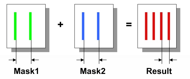
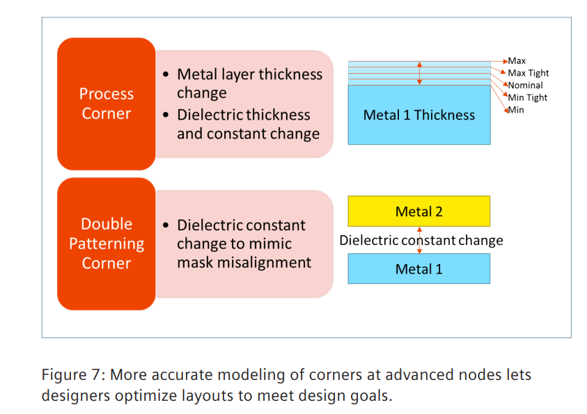
DPT effect
When using two masks per layer (Double Patterning Technology, DPT) there is an issue of mask alignment where any mis-alignment will cause layer spacing values to change, therefore changing the parasitic coupling capacitance values.
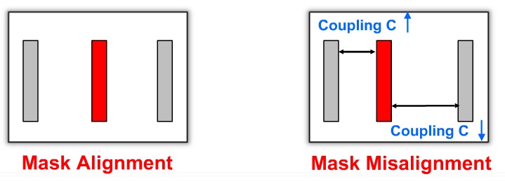
Misalignment scale and direction are not deterministic facts: coupling cap and total cap may be increased or decreased.
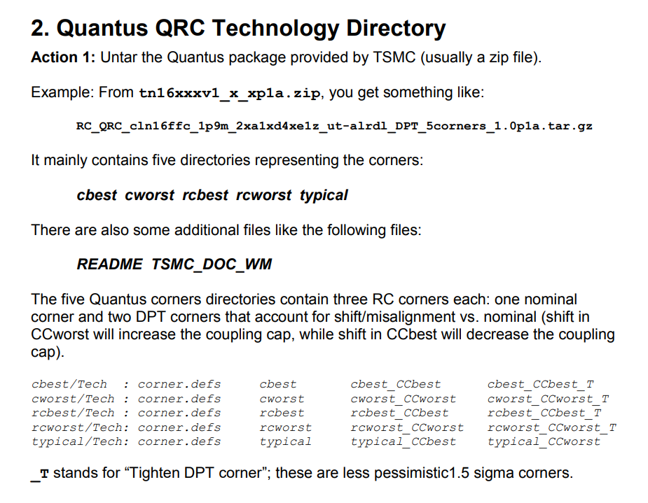
Five new corners are added in a DPT flow to account for RC variations accurately:
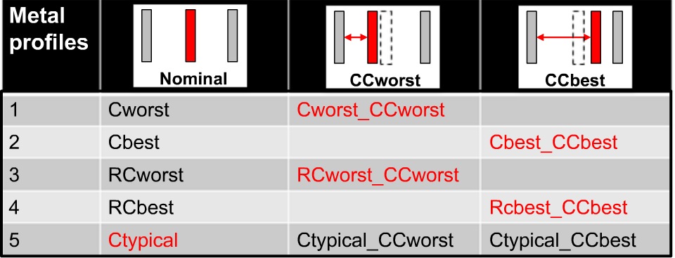
sapced-dependent side-wall dielectric constant also affect coupling cap
and CC_worst means to increase both K1 and K2
CC_best means to decrease both K1 and K2
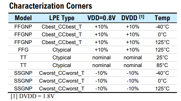
Setup time sign-off would use:
Cworst_CCworst / RCworst_CCworst
Hold time sign-off would use:
Cbest_CCbest / RCbest_CCbest / Cworst_CCworst / RCworst_CCworst
Signoff corner
| with misalignment effect | without misalignment effect |
|---|---|
| cworst_CCworst, cworst_CCworst_T | cworst, cworst_T |
| cbest_CCbest, cbest_CCbest_T | cbest, cbest_T |
| rcworst_CCworst, rcworst_CCworst_T | rcworst, rcworst_T |
| rcbest_CCbest, rcbest_CCbest_T | rcbest, rcbest_T |
BEOL Target: typical
The recommended RC corner:
cworst_CCworst, cbest_CCbest, rcworst_CCworst, rcbest_CCbest and typical
The others are for pre-color RC calculation purpose
_T stands for "Tighten DPT corner"; these are less pessimistic 1.5 sigma corners
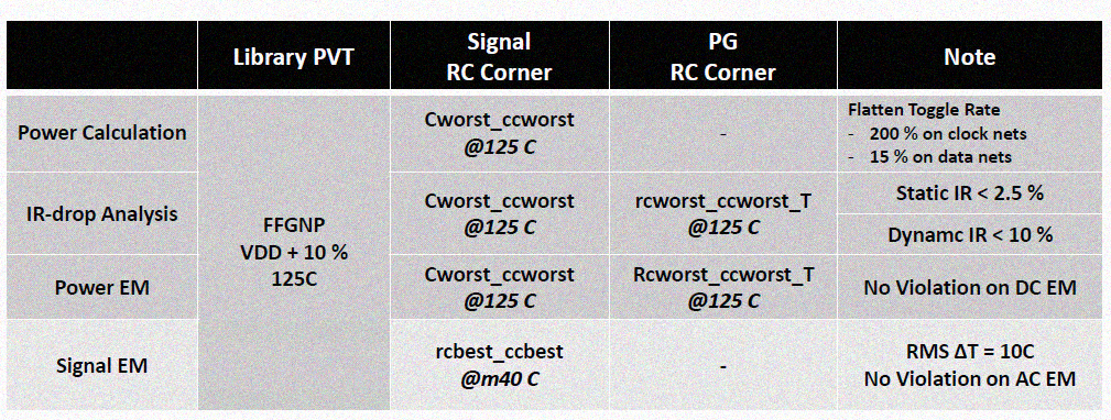
Below table is caputre of Aragio's TSMC16: LVDS datasheet
BEOL corner
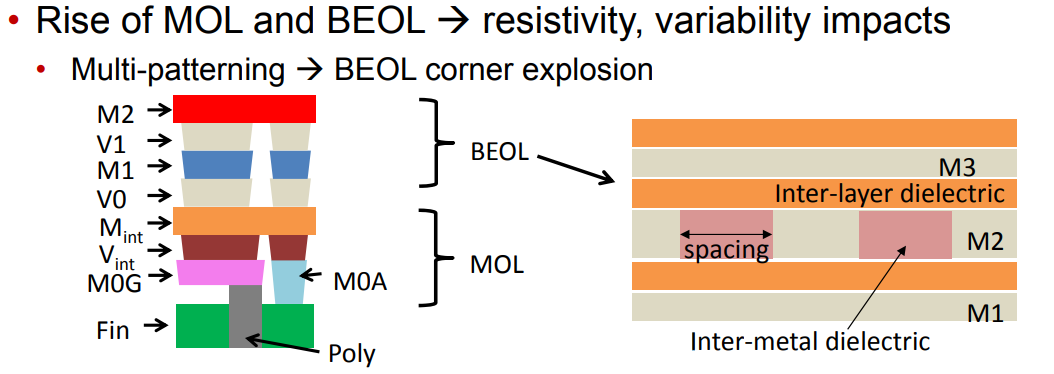
Spacing variation is implicitly defined by \(\Delta W_m\).
We denote the conductor width and thickness of the layer m by \(W_m\) and \(T_m\), respectively.
Similarly, we denote the thickness of the layer's interlayer dielectric (i.e., the distance between layer m and layer m +1) by \(H_m\)
- C-based means worst and best caps
- RC-based means worst and best R in adjustment with C (RC product)
Based on experience, it was found that C-based extraction provides worst and best case over RC for internal timing paths because Capacitance dominates short wire.
However, for large design, inter-block timing paths were often worst with RC worst parasitic since R dominates for long wires.
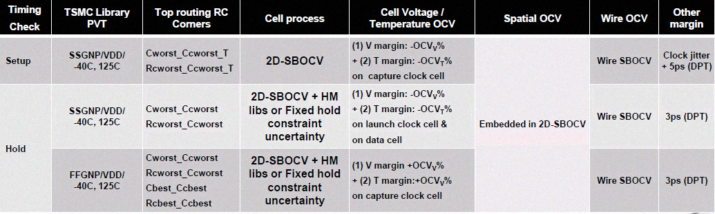
signoff corners for setup and hold
reference
Modeling Sub-90nm On-Chip Variation Using Monte Carlo Method for DFM https://www.aspdac.com/aspdac2007/pdf/archive/2D-1.pdf
Double Patterning for IC Design, Extraction and Signoff https://semiwiki.com/eda/synopsys/1974-double-patterning-for-ic-design-extraction-and-signoff/
抽刀断水水更流,RC Corner不再愁:STA之RC Corner URL: http://mp.weixin.qq.com/s?__biz=MzUzODczODg2NQ==&mid=2247484115&idx=1&sn=de99f27aadf58ea316c284dad9000b7c&chksm=fad26b0dcda5e21b8c9750f738b55053f695843a66c3c202ff0ba586c738f45aa270254c3722&scene=21#wechat_redirect
一曲新词酒一杯,RC Corner继续飞: STA之RC Corner拾遗 URL:https://mp.weixin.qq.com/s?__biz=MzUzODczODg2NQ==&mid=2247484135&idx=2&sn=bddc632850bd10c32b5688fd7af46218&chksm=fad26b39cda5e22f1c3970f8c8c2e1287c9492c526c4caf02b61f61faffdf829381c392d6ea1&scene=21#wechat_redirect
且将新火试新茶,深究趁年华:STA之RC Corner再论 URL:https://mp.weixin.qq.com/s?__biz=MzUzODczODg2NQ==&mid=2247484144&idx=1&sn=059843381e77cd4008d25166db388d02&chksm=fad26b2ecda5e23816b33b3a949f34d4ca09118bad76f1089dfcb228b7da6491f423a5f4e703&cur_album_id=1326356275000705025&scene=189#wechat_redirect
LDP_IN_800_25V_DN: 1.2GHz LVDS Receiver http://aragiosolutions.com/pdf/rgo_tsmc16_18v25_lvds_product_brief_rev_1a.pdf
Parasitic extraction technologies Advanced node and 3D-IC design https://static.sw.cdn.siemens.com/siemens-disw-assets/public/81845/en-US/Siemens-SW-Parasitic-extraction-technologies-for-advanced-WP-81845-C2.pdf
New Game, New Goal Posts: A Recent History of Timing Closure https://pdfs.semanticscholar.org/9360/5ce48f9bd3b7527ae8979f41a9c7e310efa4.pdf
The Evolution, Pitfalls, and Cargo Cult Engineering of Advanced Digital Timing Sign-off https://www.tauworkshop.com/2021/speaker_slides/christian_l.pdf
T. -B. Chan, S. Dobre and A. B. Kahng, "Improved signoff methodology with tightened BEOL corners," 2014 IEEE 32nd International Conference on Computer Design (ICCD), Seoul, Korea (South), 2014, pp. 311-316, doi: 10.1109/ICCD.2014.6974699.
Chan, T. (2014). Mitigation of Variability and Reliability Margins in IC Implementation /. UC San Diego. ProQuest ID: Chan_ucsd_0033D_14269. Merritt ID: ark:/20775/bb52916761. Retrieved from https://escholarship.org/uc/item/35r1m001
Dr. Adam Temanm, Digital VLSI Design:Lecture 10: Routing https://www.eng.biu.ac.il/temanad/files/2017/02/Lecture-10-Routing.pdf
Article (20487193) Title: Setting Pegasus - LVS to Quantus av_extracted view Flow with TSMC16 packages URL: https://support.cadence.com/apex/ArticleAttachmentPortal?id=a1O0V000009MprZUAS