Network Analysis and Scattering parameters
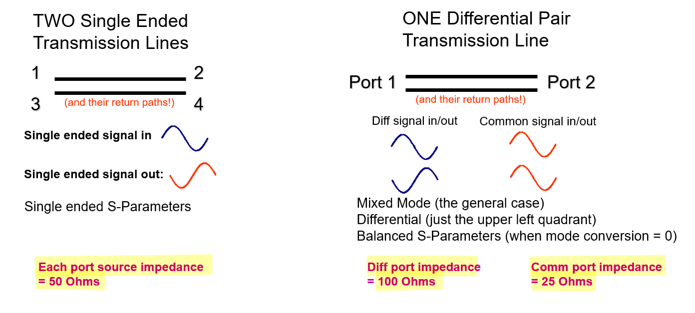
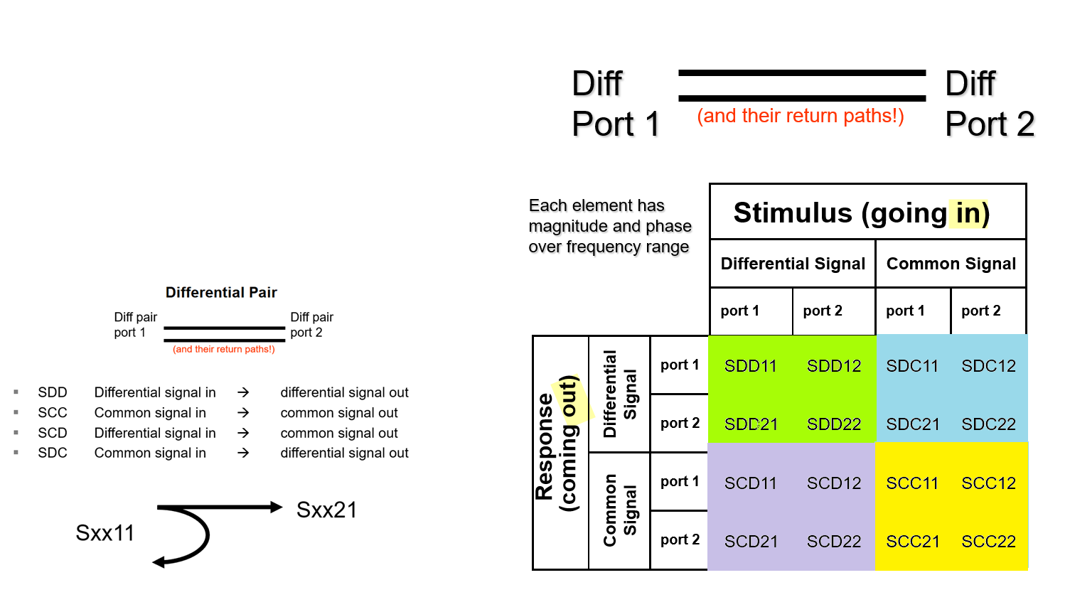
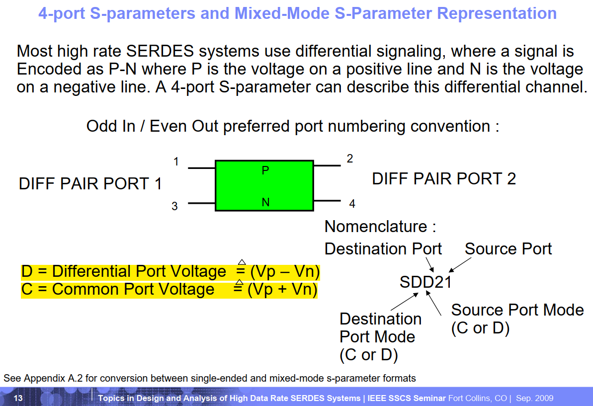
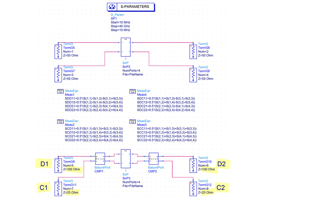
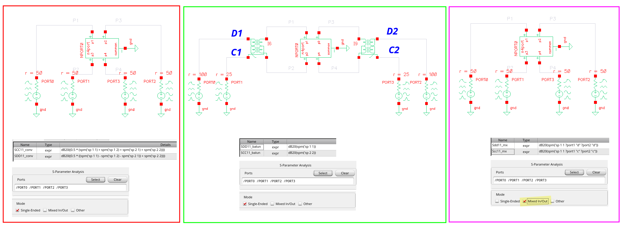
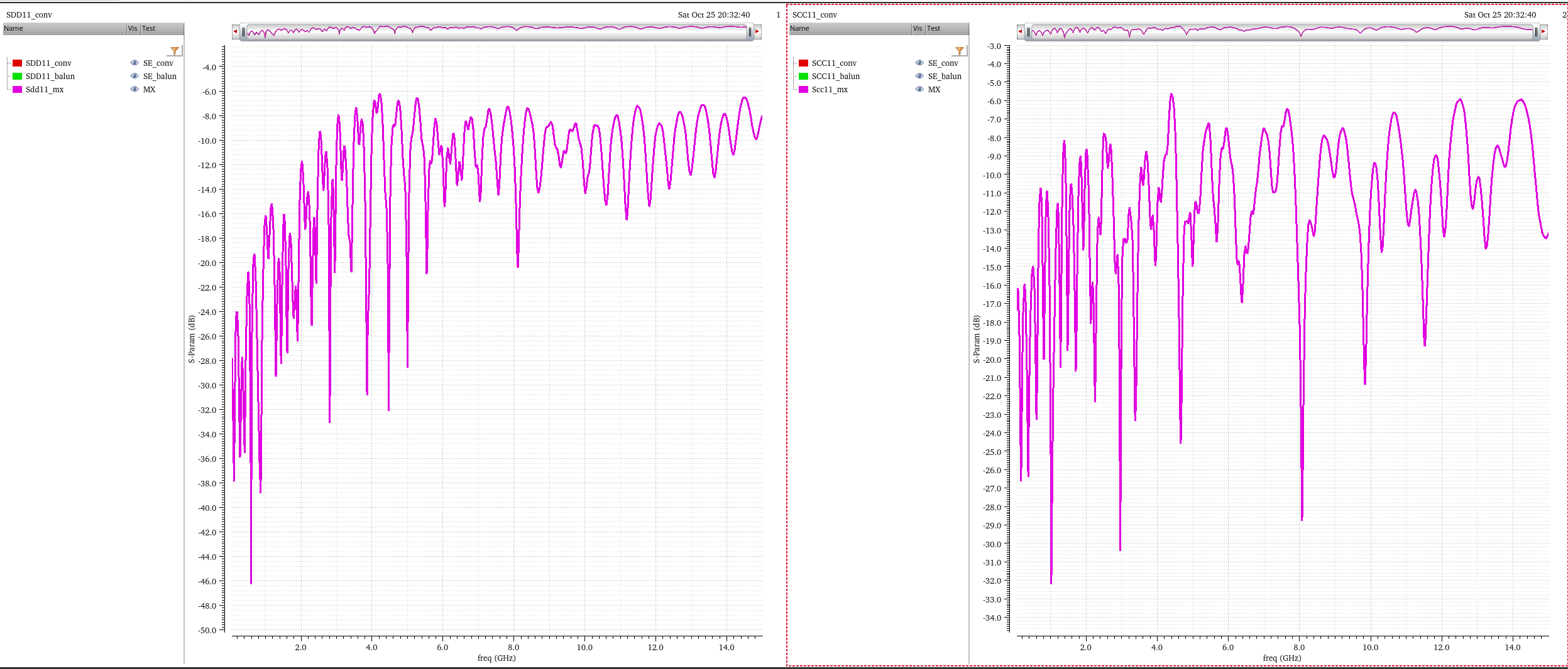
Mixed-Mode S-parameter
12 May 2021 Introduction to Mixed-Mode S-parameters [https://blog.teledynelecroy.com/2021/05/introduction-to-mixed-mode-s-parameters.html]
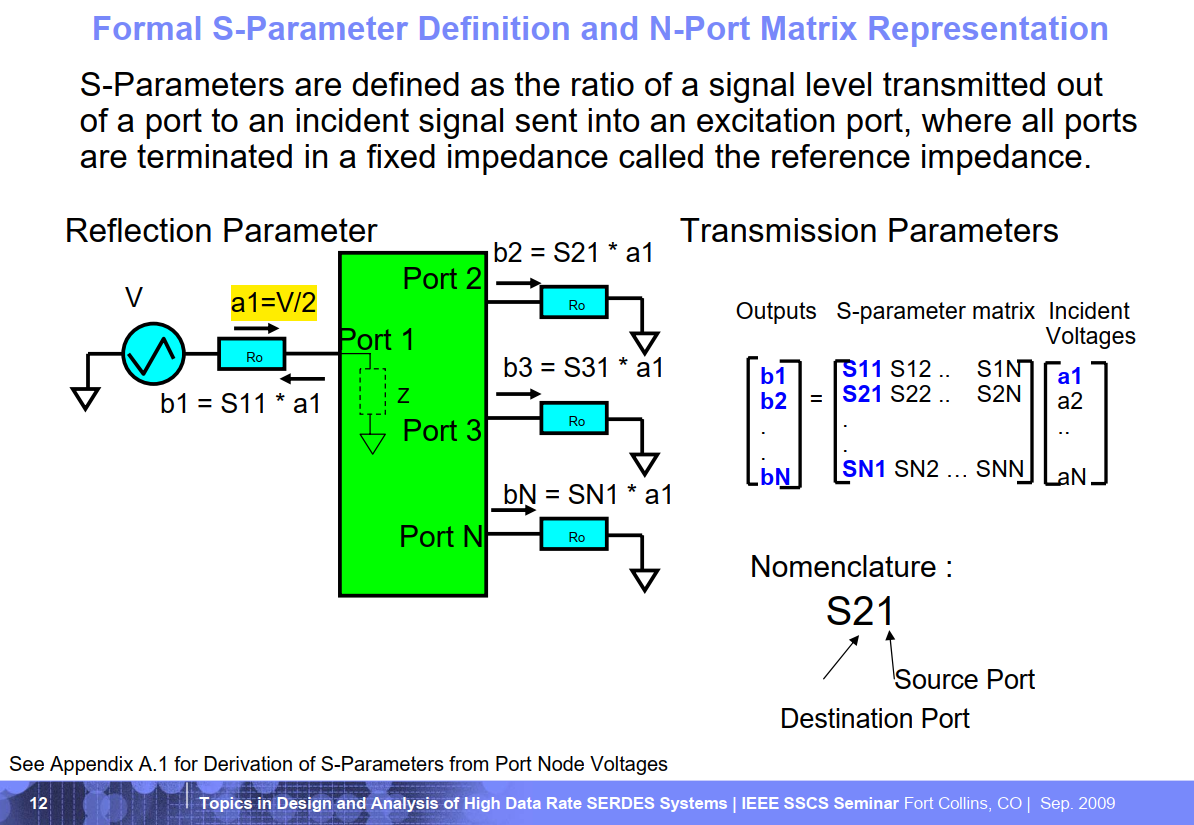
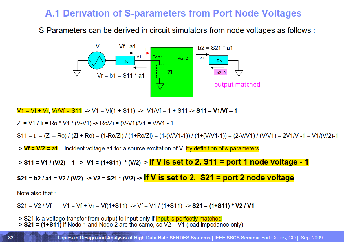
Troy Beukema (IBM Research, Yorktown Heights, NY). 03-Sep-2009. Topics in Design and Analysis of High Data Rate SERDES Systems [https://ewh.ieee.org/r5/denver/sscs/Presentations/2009_09_Beukema.pdf]

Bert Simonovich. A Guide for Single-Ended to Mixed-Mode S-parameter Conversions [https://www.signalintegrityjournal.com/articles/1832-a-guide-for-singleended-to-mixedmode-s-parameter-conversions]
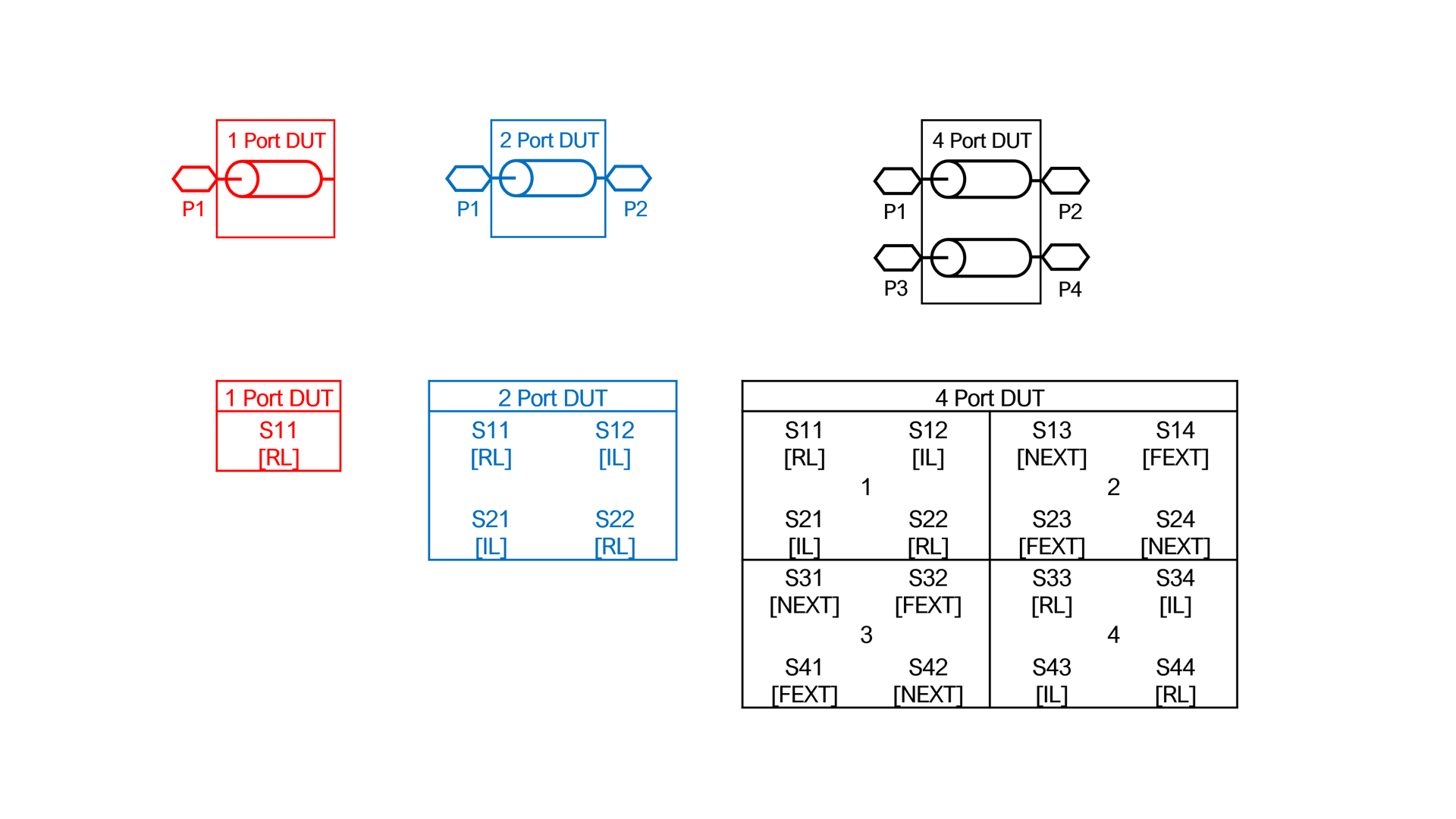
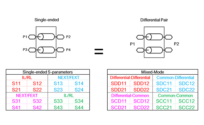
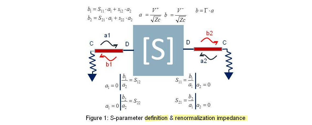
single-ended S-parameters
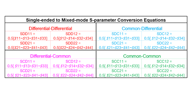
Mixed-mode S-parameters
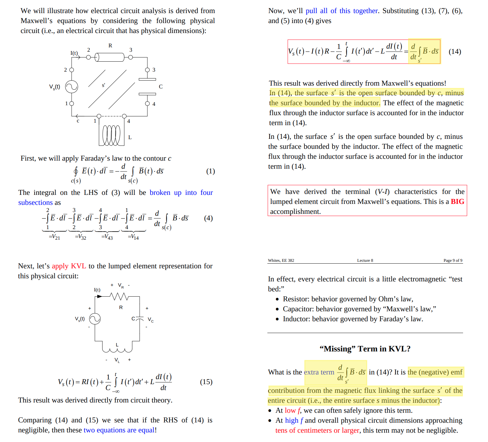
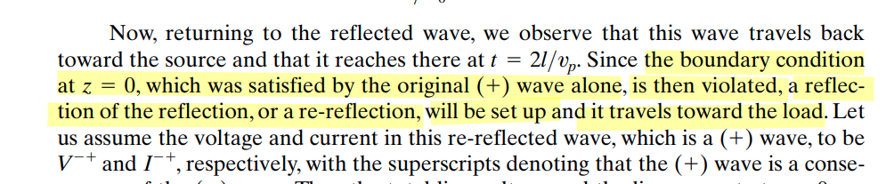
Missing Term in KVL
Prof. Kolb/Whites. EE 382 Applied Electromagnetics Lecture 8: Maxwell's Equations and Electrical CIrcuits [http://montoya.sdsmt.edu/ee382/lectures/382Lecture8.pdf]
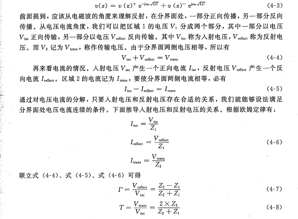
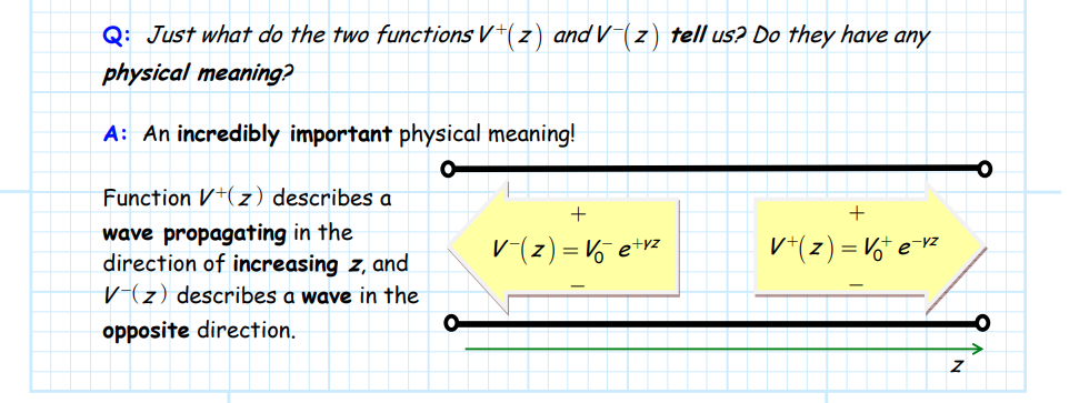
Transmission-line
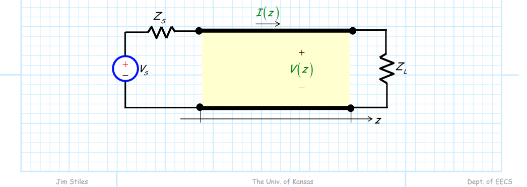
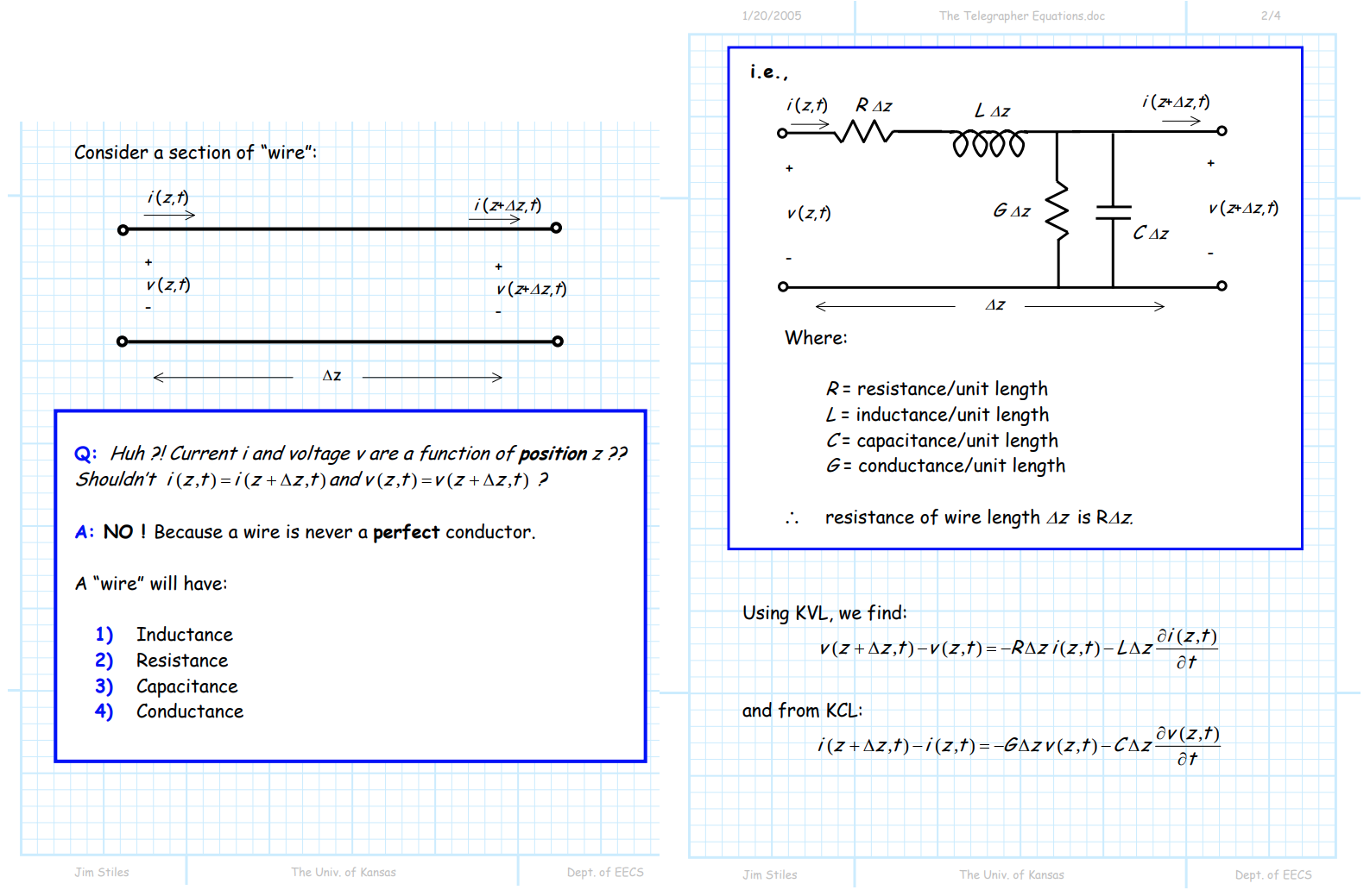
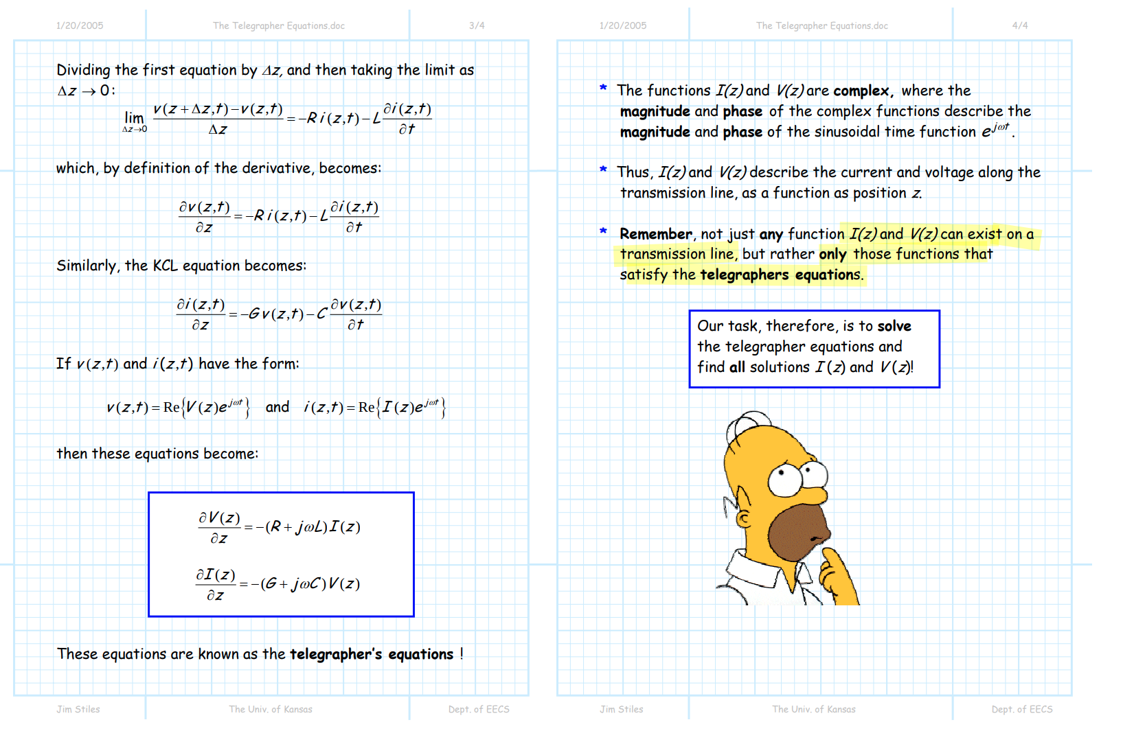
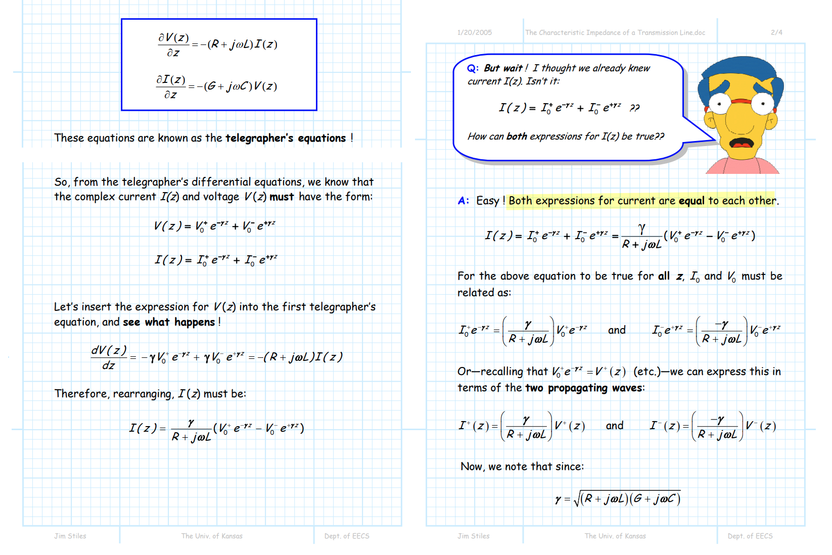
Telegrapher's equations
EECS 723- Microwave Engineering Spring 2.1 -The Lumped Element Circuit Model for Transmission Lines
1/20/2005 [https://www.ittc.ku.edu/~jstiles/723/handouts/2_1_Lumped_Element_Circuit_Model_package.pdf]
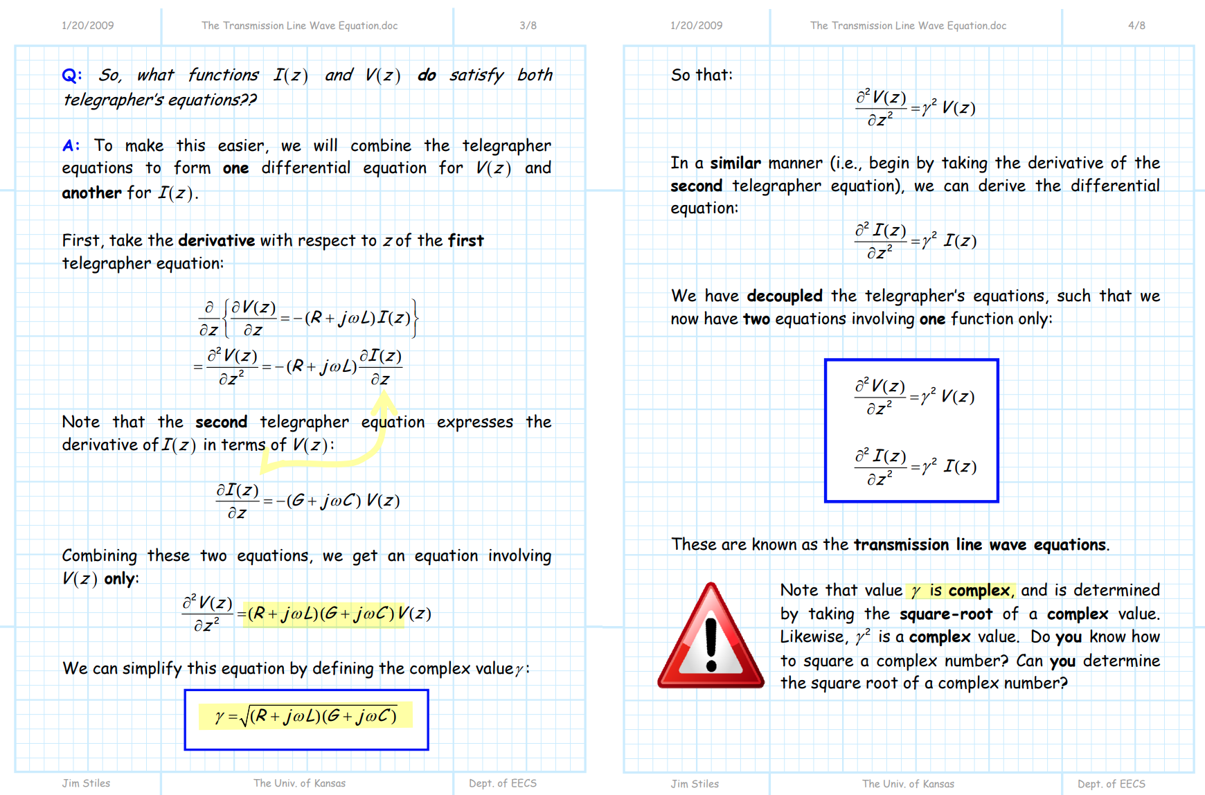
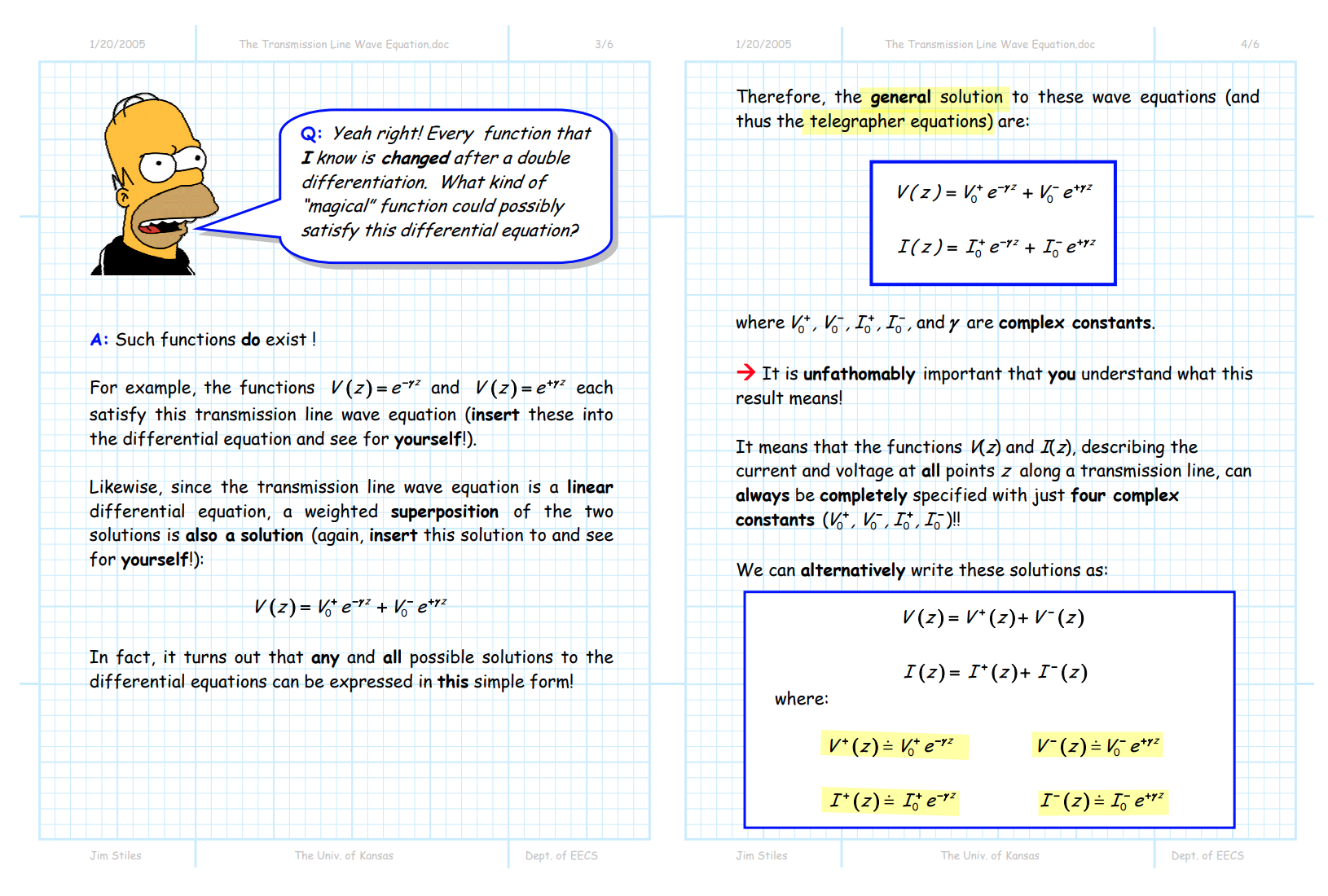
Transmission Line Wave Equation
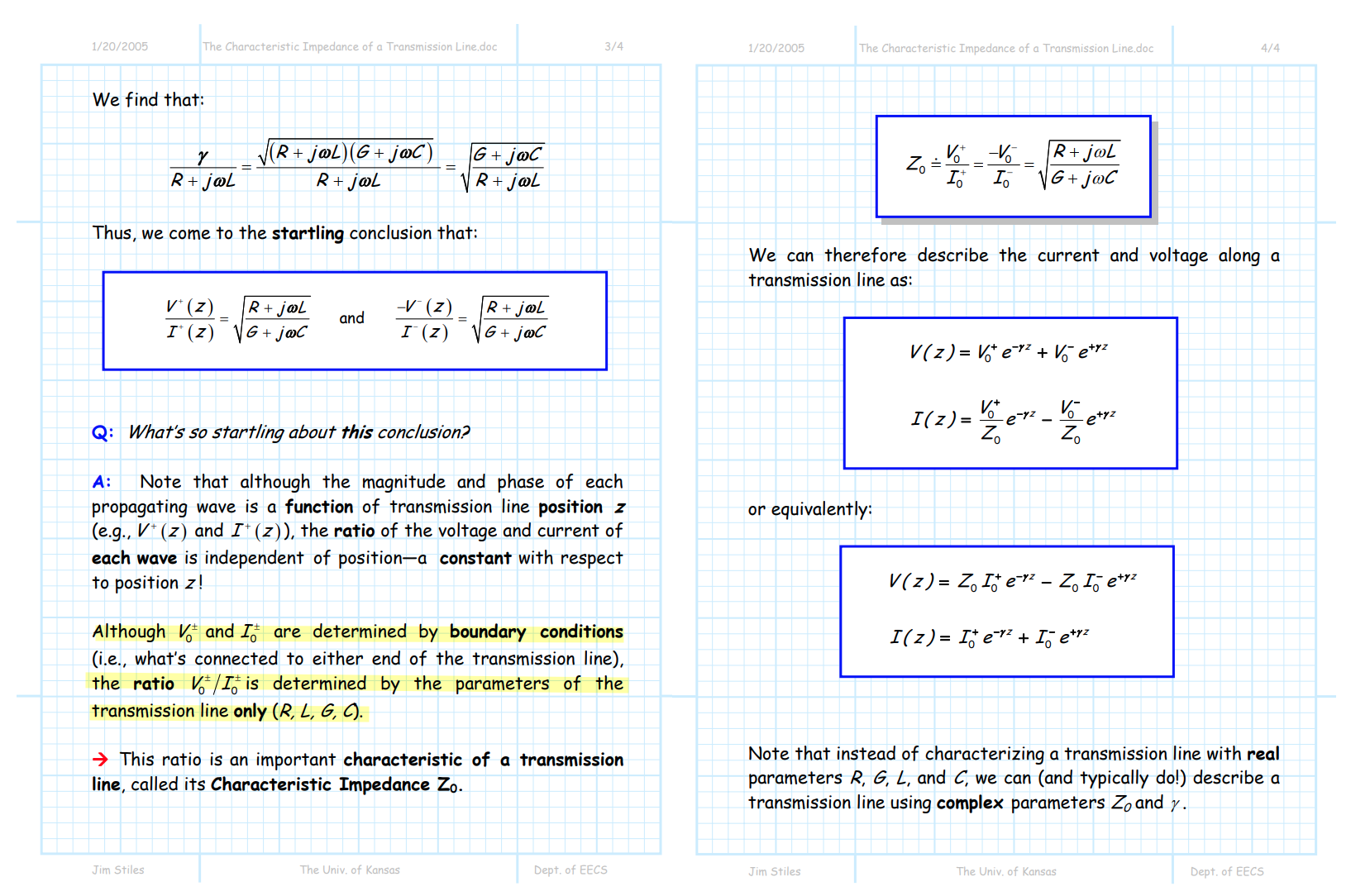
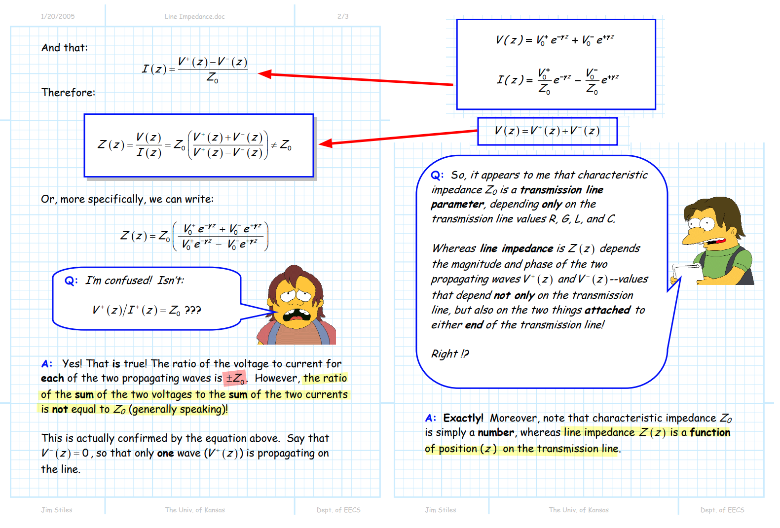
Characteristic Impedance (\(Z_0\))
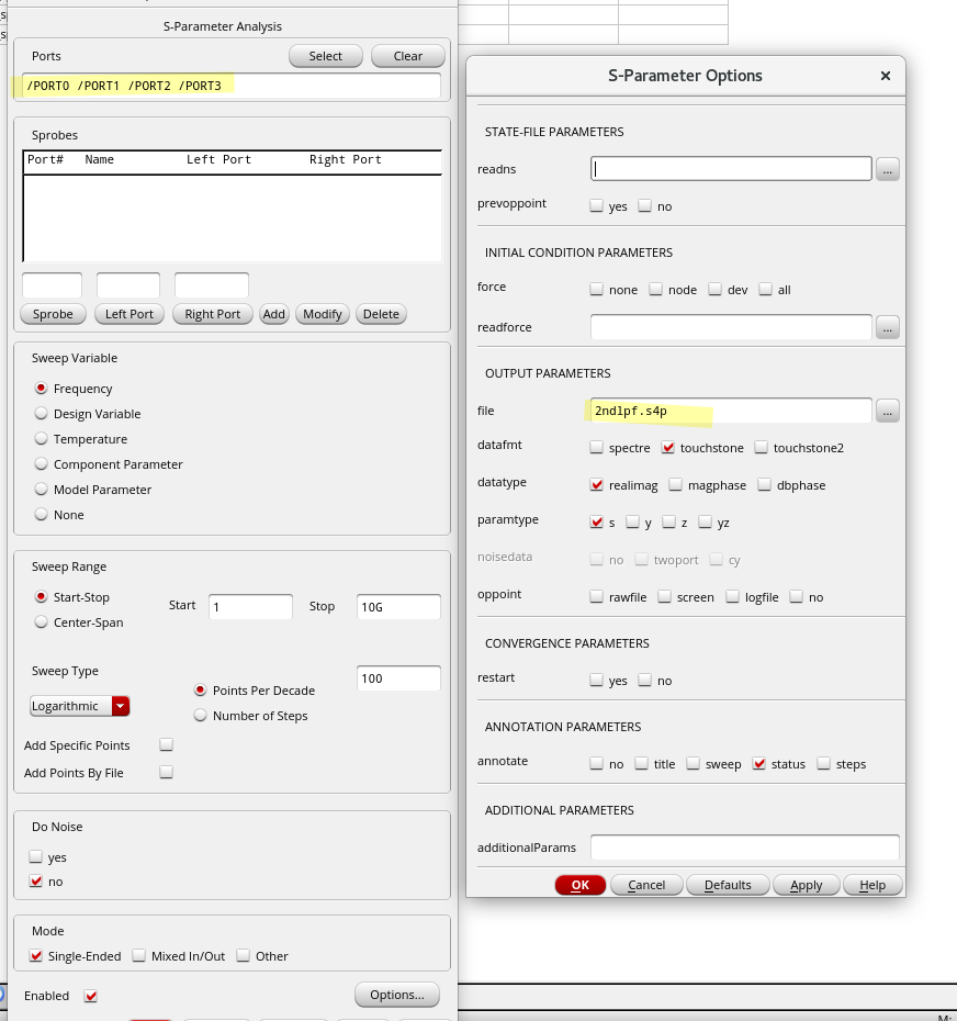
Remember, S-parameters don't mean much unless you know the value of the reference impedance (it's frequently called Z0).
simulator will read sp file's Z0 parameter
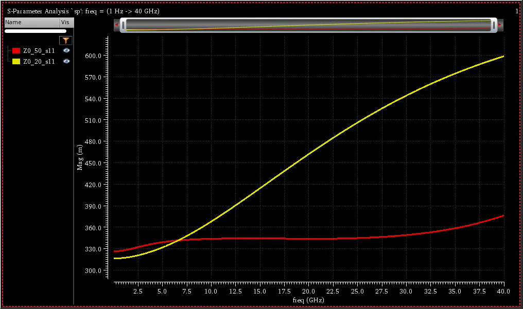
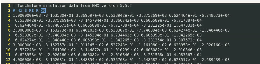
The default Z0 exported by EMX is 50
Complex Propagation Constant \(\gamma\)
TODO 📅
Input impedance (Line Impedance)
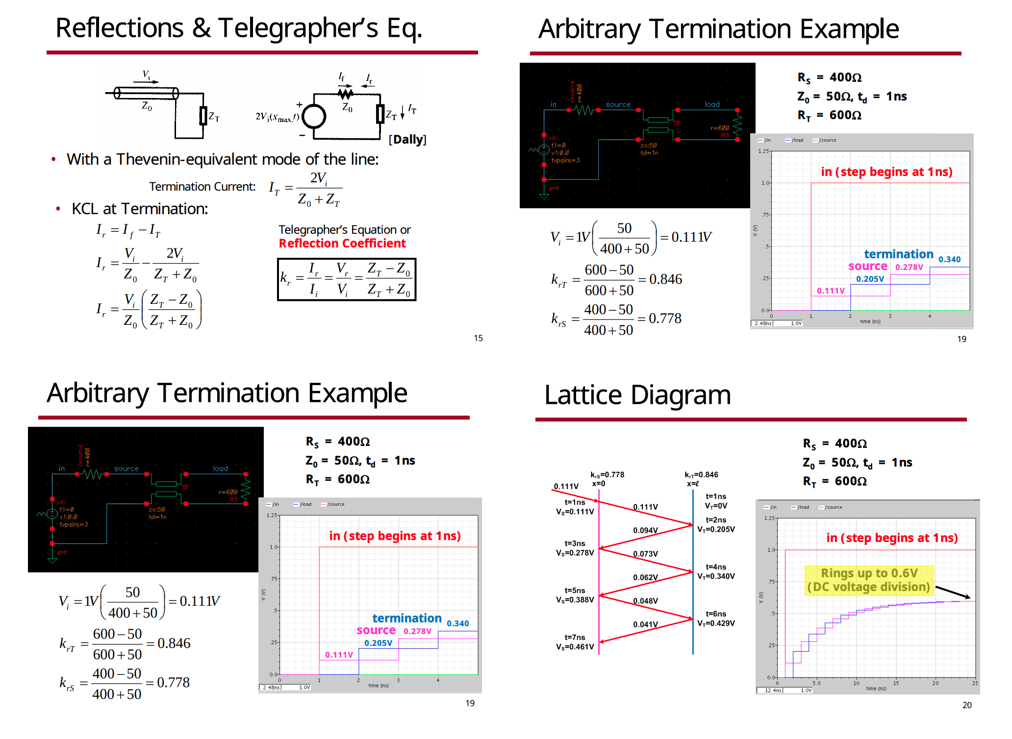
Reflection Coefficient
TODO 📅
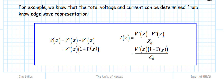
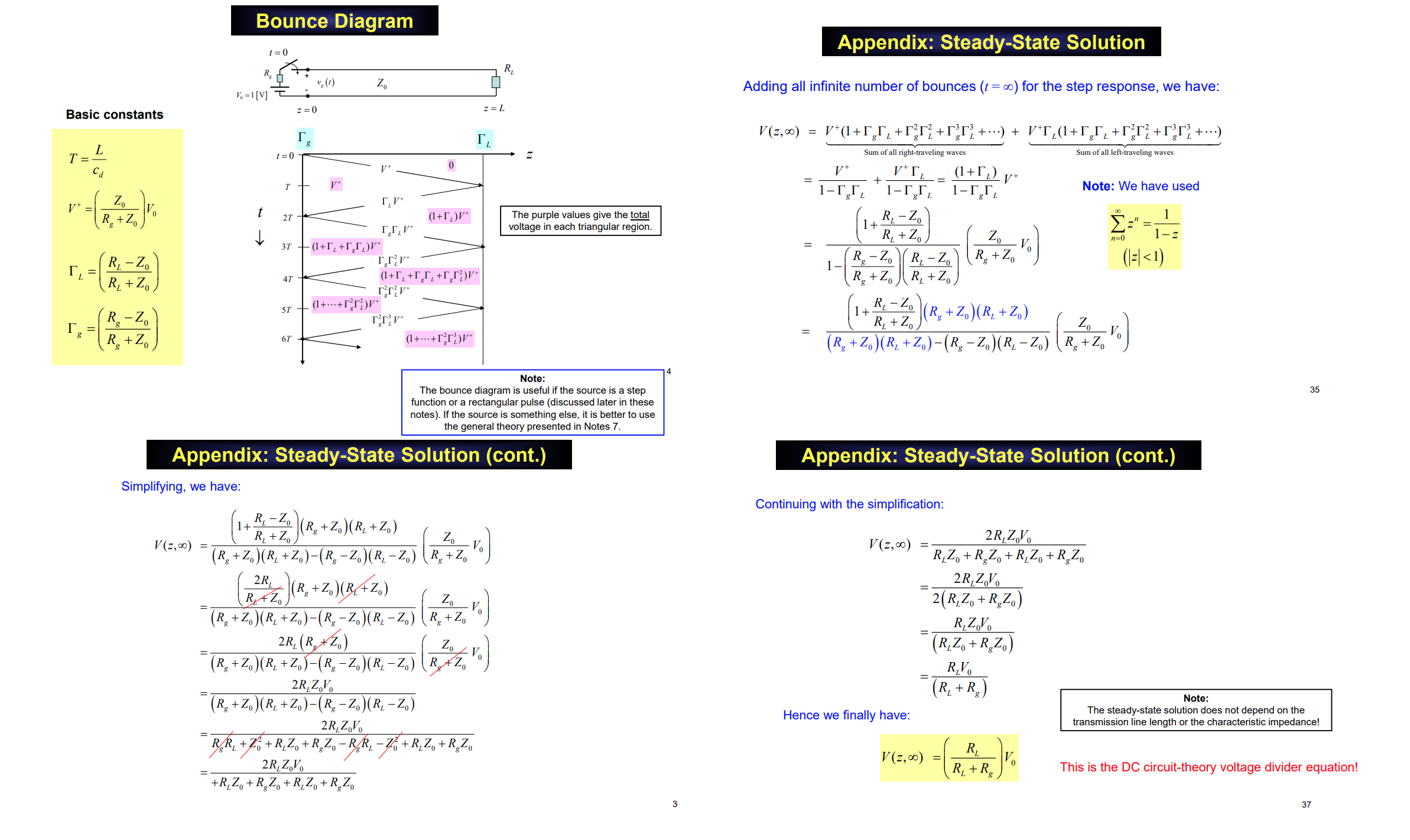
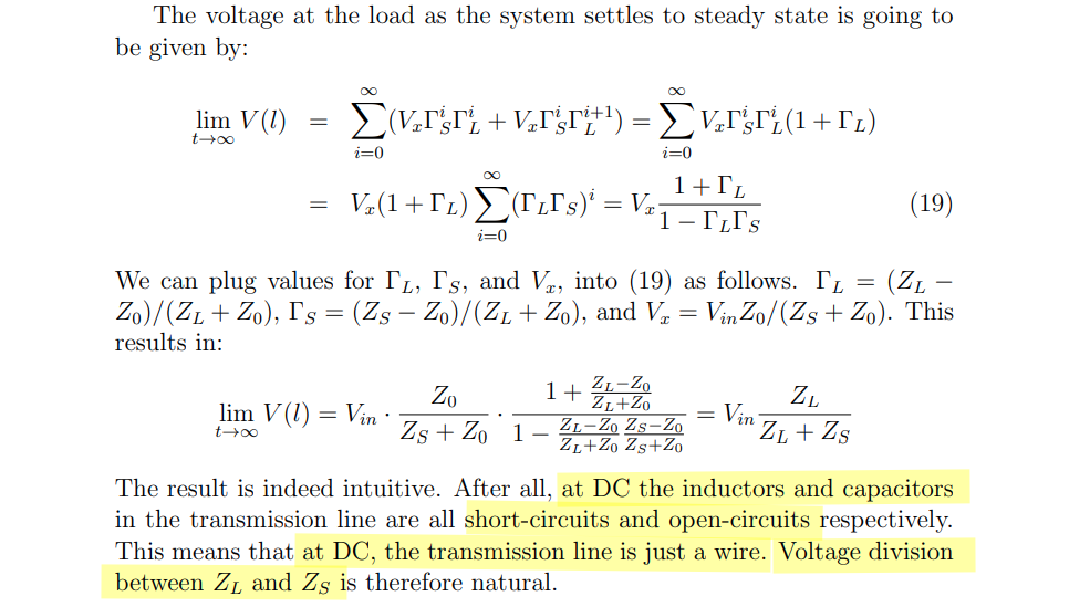
Steady-State Solution (DC voltage division)
Sam Palermo. [https://people.engr.tamu.edu/spalermo/ecen689/lecture3_ee689_tlines.pdf]
Kyoung-Jae Chung. Special Topics in Radiation Engineering (High-voltage pulsed power engineering) [https://ocw.snu.ac.kr/sites/default/files/NOTE/Lecture_03_Transmission%20line%20theory.pdf]
David R. Jackson. [https://courses.egr.uh.edu/ECE/ECE3317/SectionJackson/Class%20Notes/Notes%208%203317%20Transmission%20Lines%20(Bounce%20Diagram).pdf]
Shouri Chatterjee [https://web.iitd.ac.in/~shouri/ell112/material/txline.pdf]
How can I go from transmission line model to lumped elements model? [https://physics.stackexchange.com/a/386603]
E157 Introduction to Radio Frequency Circuit Design [https://pages.hmc.edu/mspencer/e157/fa24/]
Shen Lin. On-Chip Inductance and Coupling Effects [http://eda.ee.ucla.edu/pub/asic.pdf]
A. Deutsch et al., "When are transmission-line effects important for on-chip interconnections?," in IEEE Transactions on Microwave Theory and Techniques, vol. 45, no. 10, pp. 1836-1846, Oct. 1997
Ho, Ron. “Chip Wires: Scaling and Efficiency.” (2003). [https://www-vlsi.stanford.edu/people/alum/pdf/0303_Ho_Wires.pdf]
—. ISSCC 2007 T3: Dealing with Issues in VLSI Interconnect Scaling, by Ron Ho
Tony Chan Carusone. ISSCC 2017 T6: Signal Integrity Analysis for Gb/s Links
Byungsub Kim ISSCC 2022 T11: "Basics of Equalization Techniques: Channels, Equalization, and Circuits"
Power Wave Equations
Peter J. Pupalaikis (Ciena). DesignCon 2026: Port Referencing in S-Parameters – Critical Insights You Need to Know
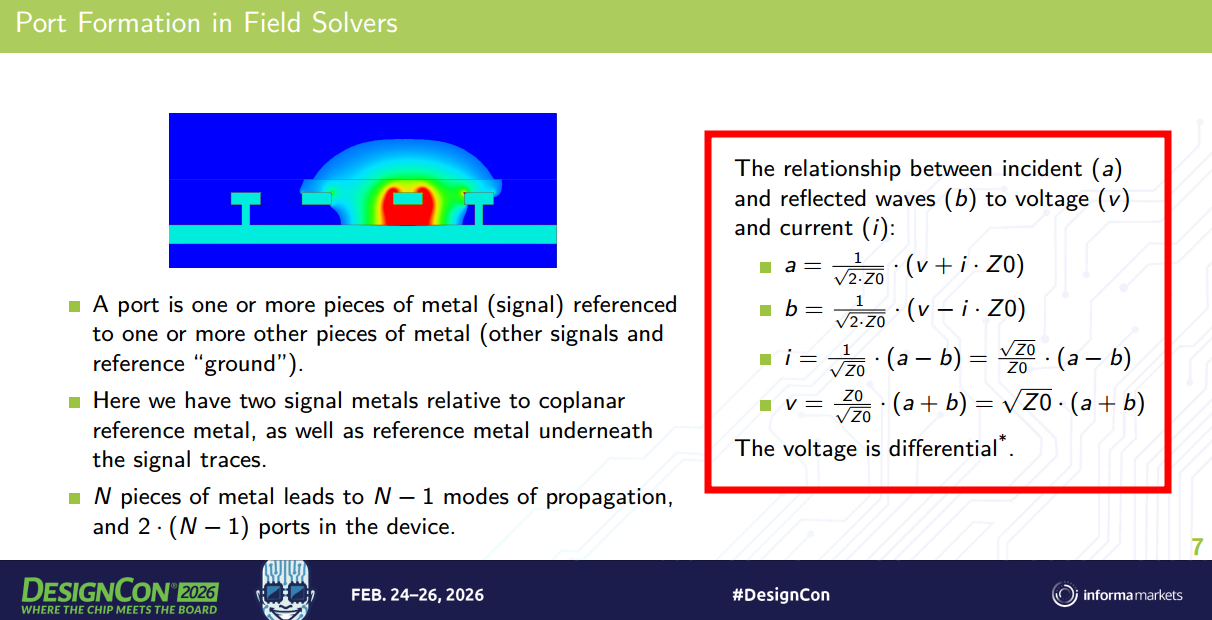
1 | Transmission Line Theory |
Z0 is a chosen reference impedance (typically 50Ω), which is an arbitrary normalization choice. It does not have to equal the characteristic impedance of the transmission line
Voltage scattering
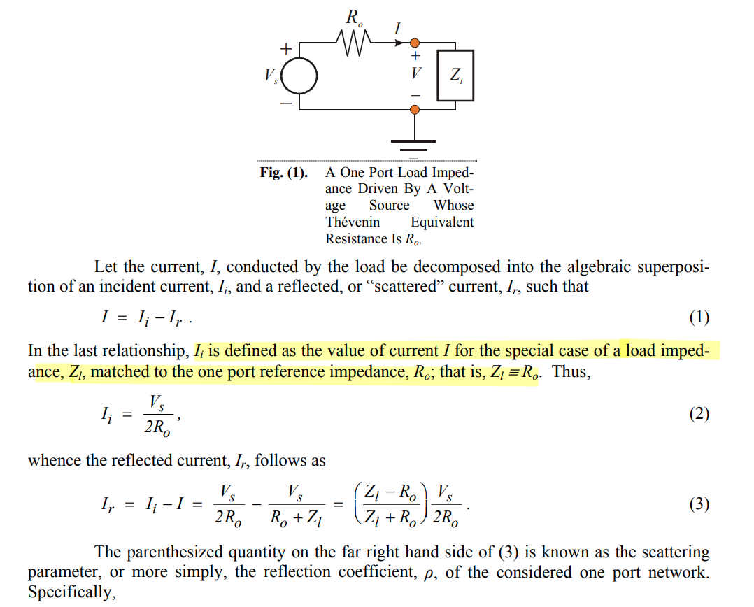
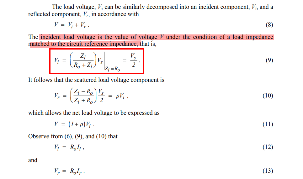
transmitted voltage \[ V= \frac{2Z_l}{Z_l+R_0}\frac{V_s}{2}= \frac{Z_l}{Z_l+R_0}\cdot V_s \]
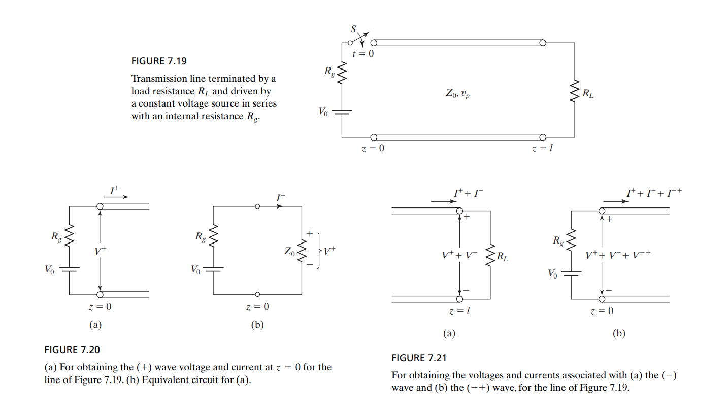
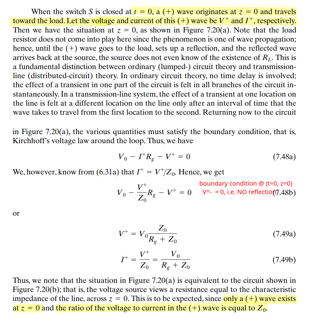
CHAPTER 6 Transmission-Line Essentials for Digital Electronics [https://ws.engr.illinois.edu/sitemanager/getfile.asp?id=178]
CHAPTER 7 Transmission-Line Analysis [https://ws.engr.illinois.edu/sitemanager/getfile.asp?id=199]
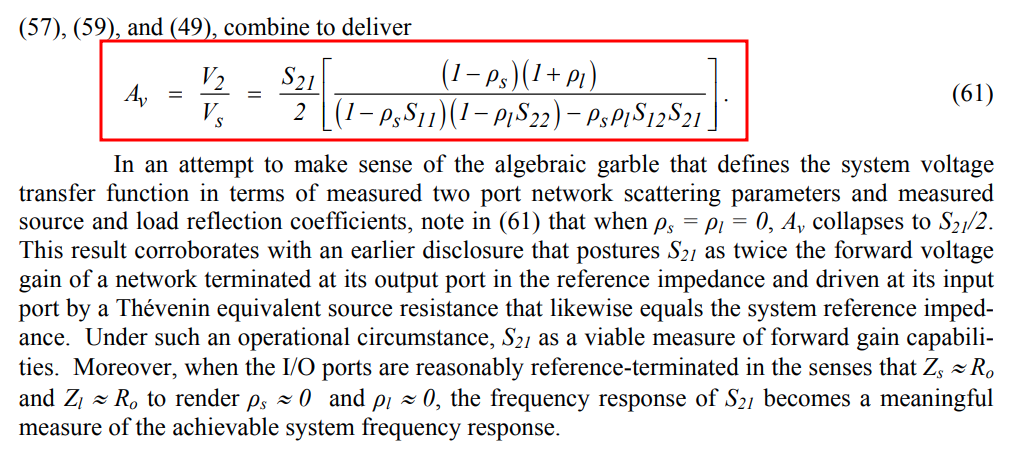
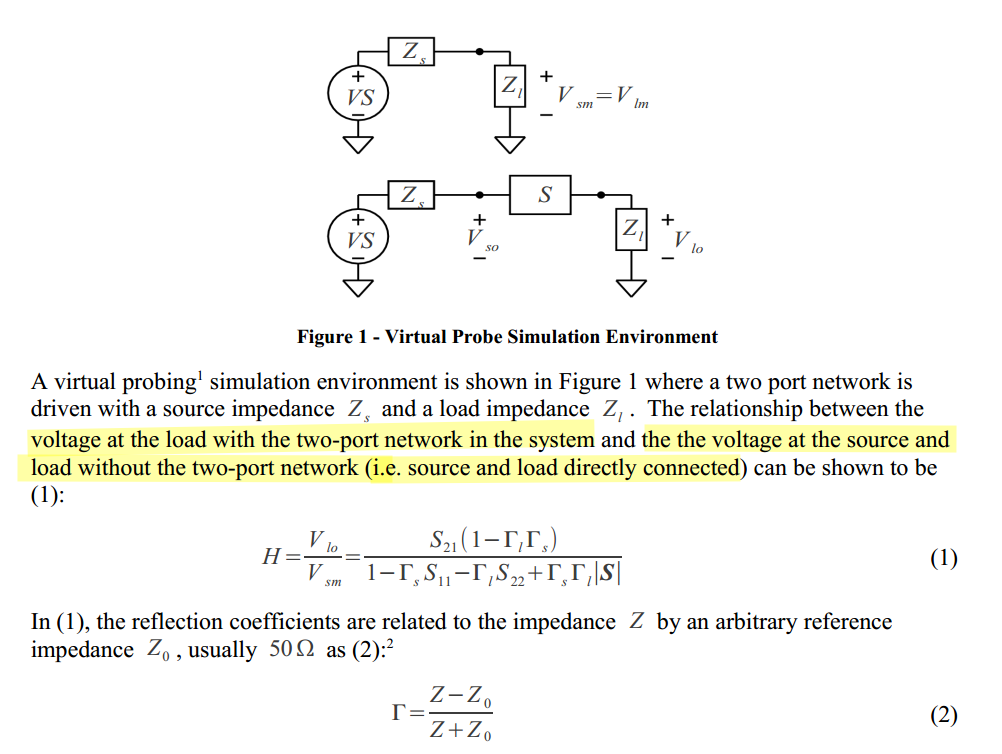
Voltage Transfer Function
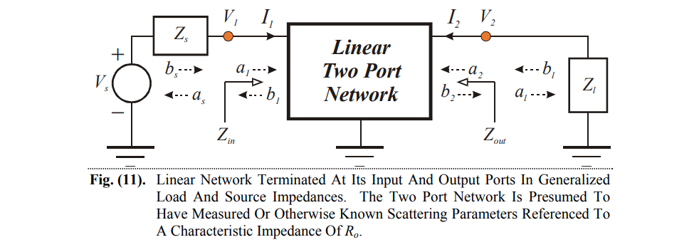

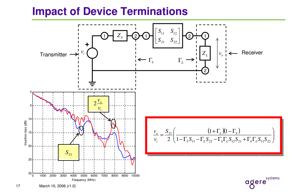
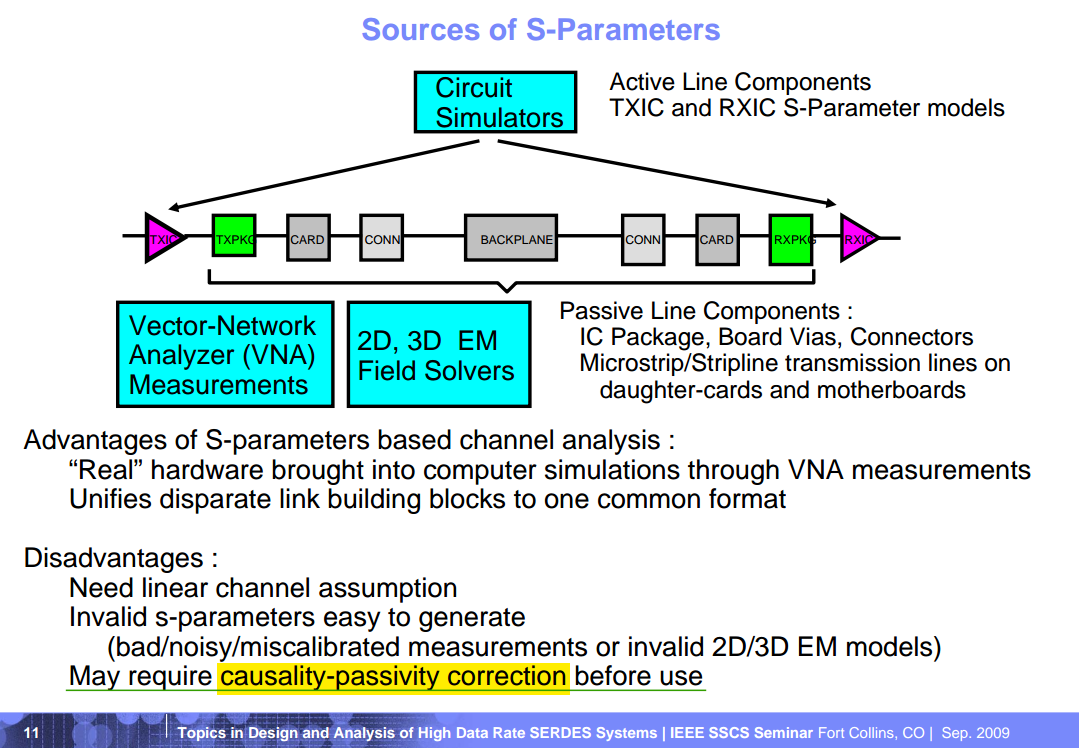
Troy Beukema (IBM Research, Yorktown Heights, NY). 03-Sep-2009. Topics in Design and Analysis of High Data Rate SERDES Systems [https://ewh.ieee.org/r5/denver/sscs/Presentations/2009_09_Beukema.pdf]
Pupalaikis, Peter. (2012). The Relationship Between Discrete-Frequency S-parameters and Continuous-Frequency Responses. [pdf]
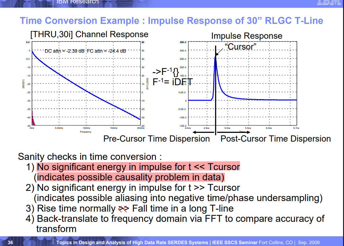
Impulse Response from S-Parameters (channel)
David Banas. A comparison of different techniques (i.e. - windowing, vector fitting, etc.) for extracting the impulse response from S-parameters. [https://github.com/capn-freako/ImpulseResponseFromSparameters/tree/main]
—, Impulse Response from Insertion Loss [https://www.signalintegrityjournal.com/articles/1847-impulse-response-from-insertion-loss]
Sam Palermo. ECEN720: High-Speed Links Circuits and Systems Spring 2025 - Lecture 3: Time-Domain Reflectometry & S-Parameter Channel Models [https://people.engr.tamu.edu/spalermo/ecen689/lecture3_ee720_tdr_spar.pdf]
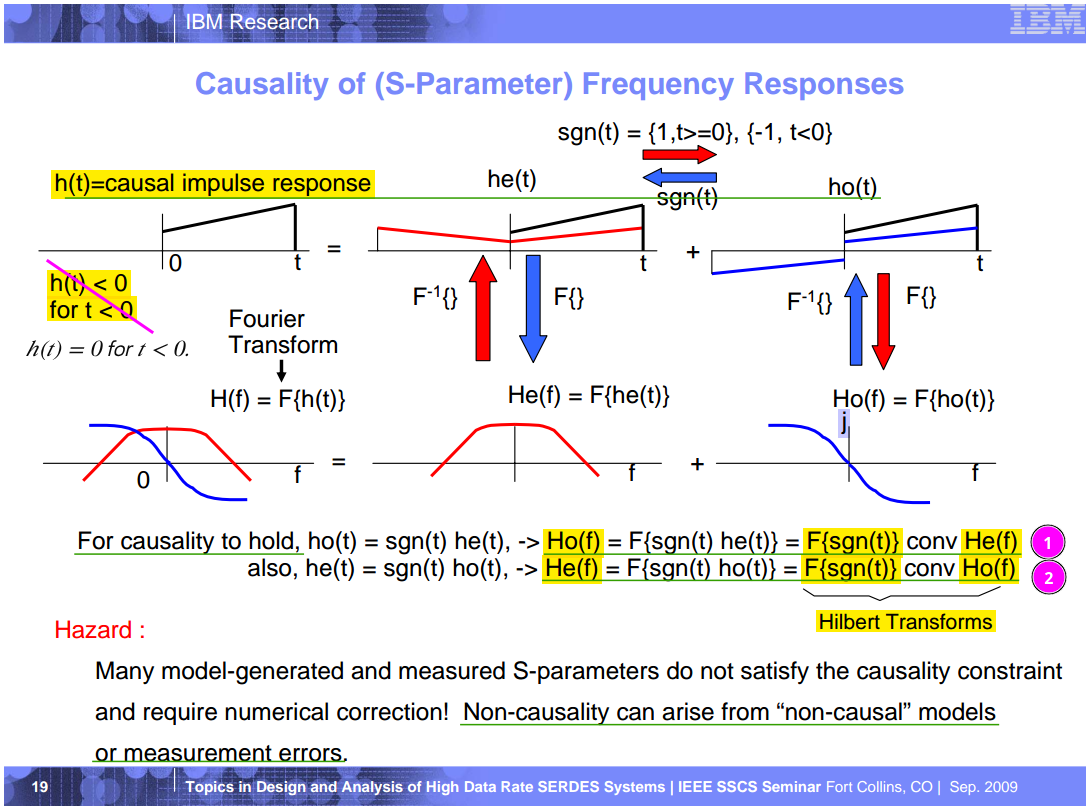
Troy Beukema (IBM Research, Yorktown Heights, NY). 03-Sep-2009. Topics in Design and Analysis of High Data Rate SERDES Systems [https://ewh.ieee.org/r5/denver/sscs/Presentations/2009_09_Beukema.pdf]
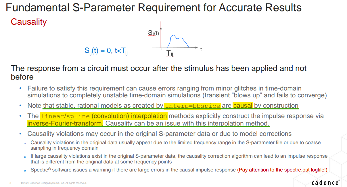
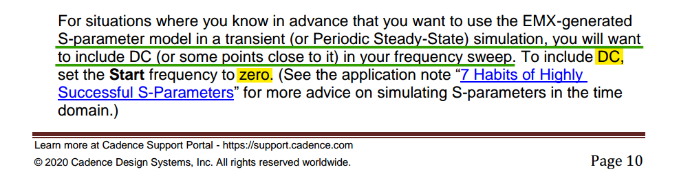
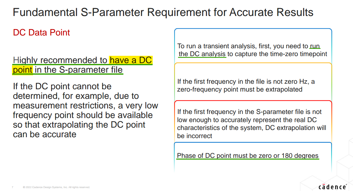
Cadence application note: 7 Habits of Highly Successful S-Parameters, Spectre 21.1
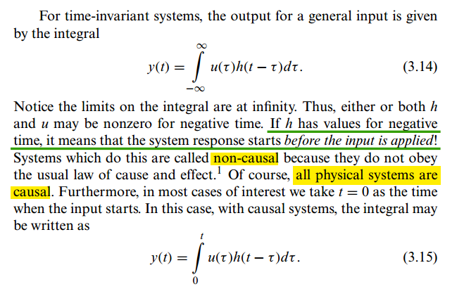
Derek Rowell, 2.161 Signal Processing: Continuous and Discrete Fall 2008: Determining a System’s Causality from its Frequency Response [https://ocw.mit.edu/courses/2-161-signal-processing-continuous-and-discrete-fall-2008/142cd928b3b3959721198872ab97b647_causality.pdf]
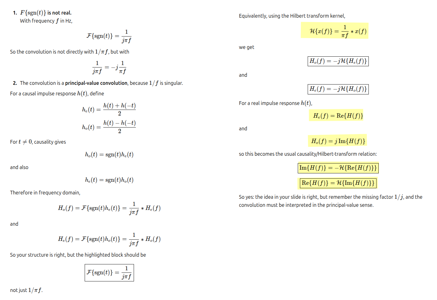
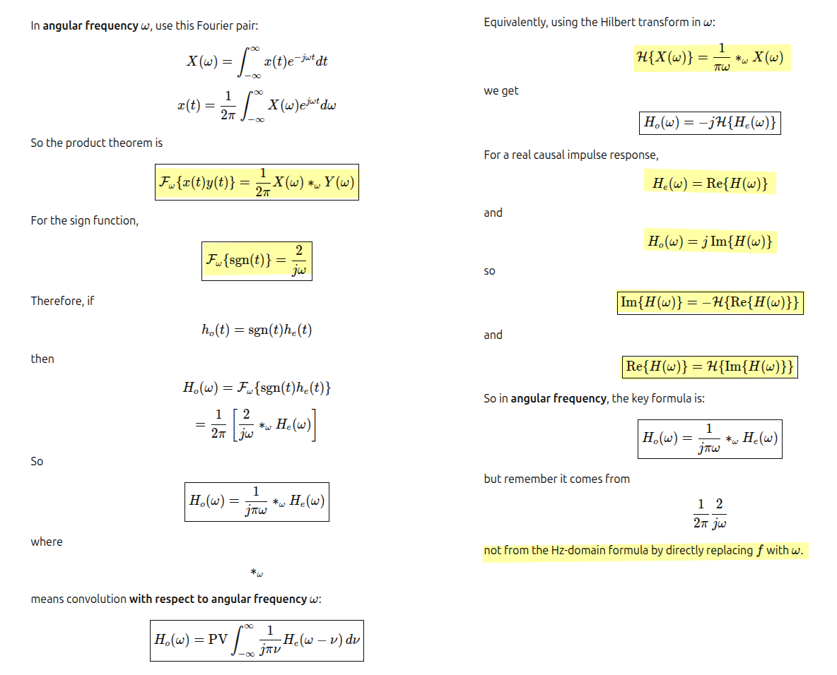
Causality
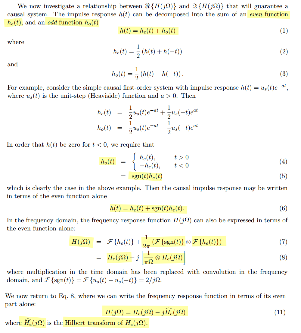
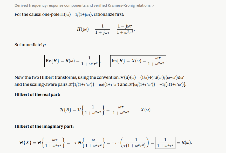
Kramers–Kronig / Hilbert-transform causality relation — Magnitude/real part and phase/imaginary part cannot be chosen independently. \[ \boxed{H_I(\omega) = -\mathcal{H}\{H_R(\omega)\}} \qquad \boxed{H_R(\omega) = \mathcal{H}\{H_I(\omega)\}} \] where \(H_R(\omega) = \operatorname{Re}\{H(\omega)\}\) and \(H_I(\omega) = \operatorname{Im}\{H(\omega)\}\)
Conjugate symmetry only ensures the time-domain signal is real
Hz-domain formula
angular frequency formula
single pole low pass filter
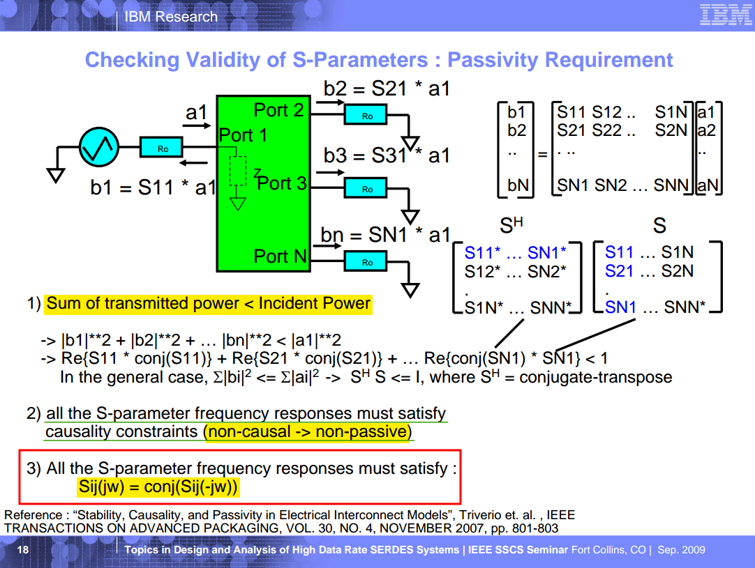
Passivity
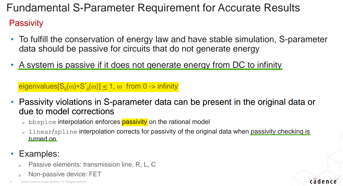
causality-passivity correction
P. Triverio, S. Grivet-Talocia, M. S. Nakhla, F. G. Canavero and R. Achar, "Stability, Causality, and Passivity in Electrical Interconnect Models," in IEEE Transactions on Advanced Packaging, vol. 30, no. 4, pp. 795-808, Nov. 2007 [https://sci-hub.ru/10.1109/TADVP.2007.901567]
S. Sercu, C. Kocuba, J. Nadolny, "Causality Demystified", in DesignCon 2015, Jan. 2015 [pdf]
Vinod Arjun Huddar. Causality Problems in Power Delivery Networks [https://www.signalintegrityjournal.com/articles/1217-causality-in-power-delivery-network-in-package-board]
Tyler Huddleston, Signal Edge Solutions. Causality in Practice: How Frequency Sampling and Bandwidth Shape Time-Domain Fidelity [https://www.signalintegrityjournal.com/articles/4061-causality-in-practice-how-frequency-sampling-and-bandwidth-shape-time-domain-fidelity]
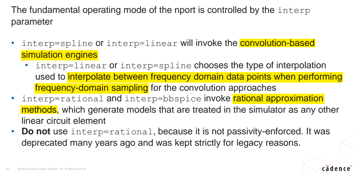
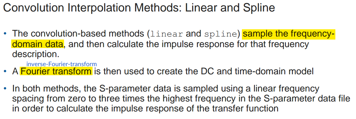
Interpolation Methods
jinghua Huang SYNOPSYS. Optimum Frequency Sampling in S-Parameter Extraction and Simulation [https://ibis.org/summits/nov08a/huang.pdf]
convolution-based method (ifft):
linear,splinerational approximation method:
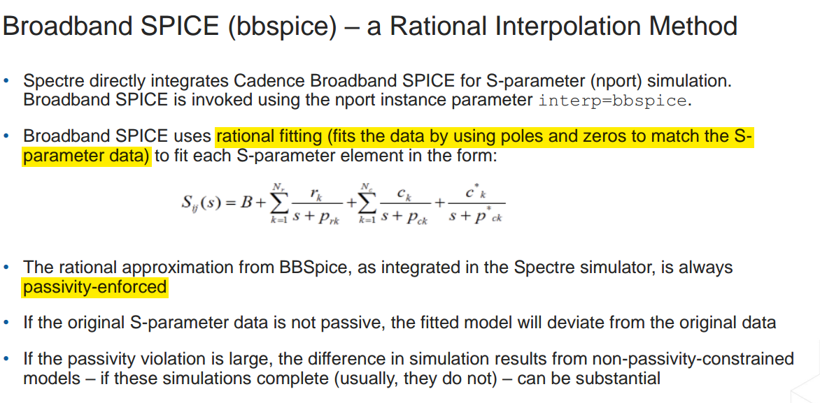
bbspice,rational
Broadband SPICE (bbspice) – a Rational Interpolation Method
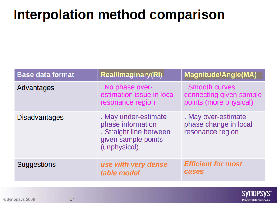
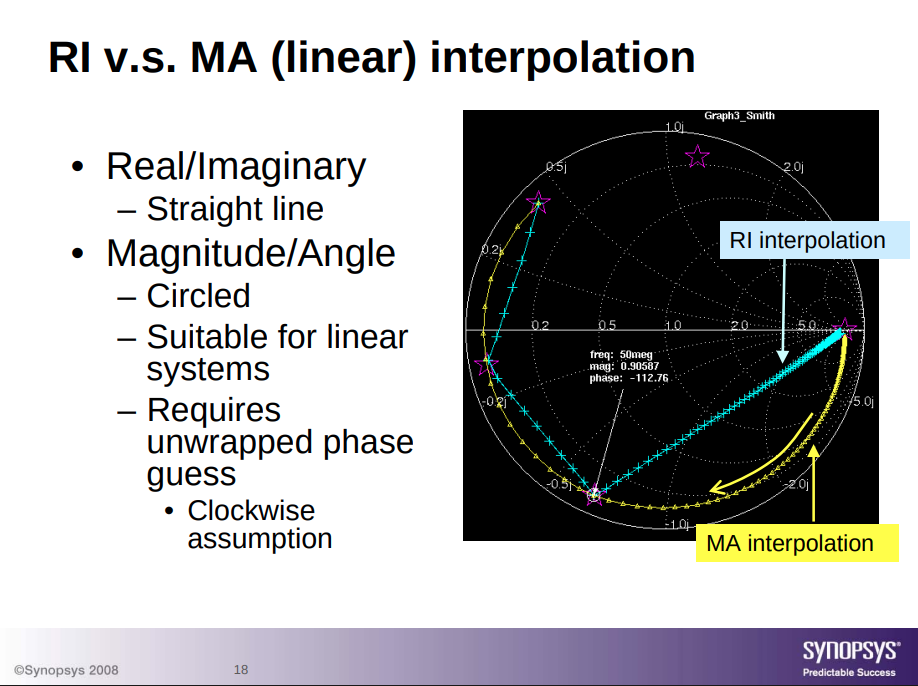
Real/Imaginary(RI) Magnitude/Angle(MA) interpolation
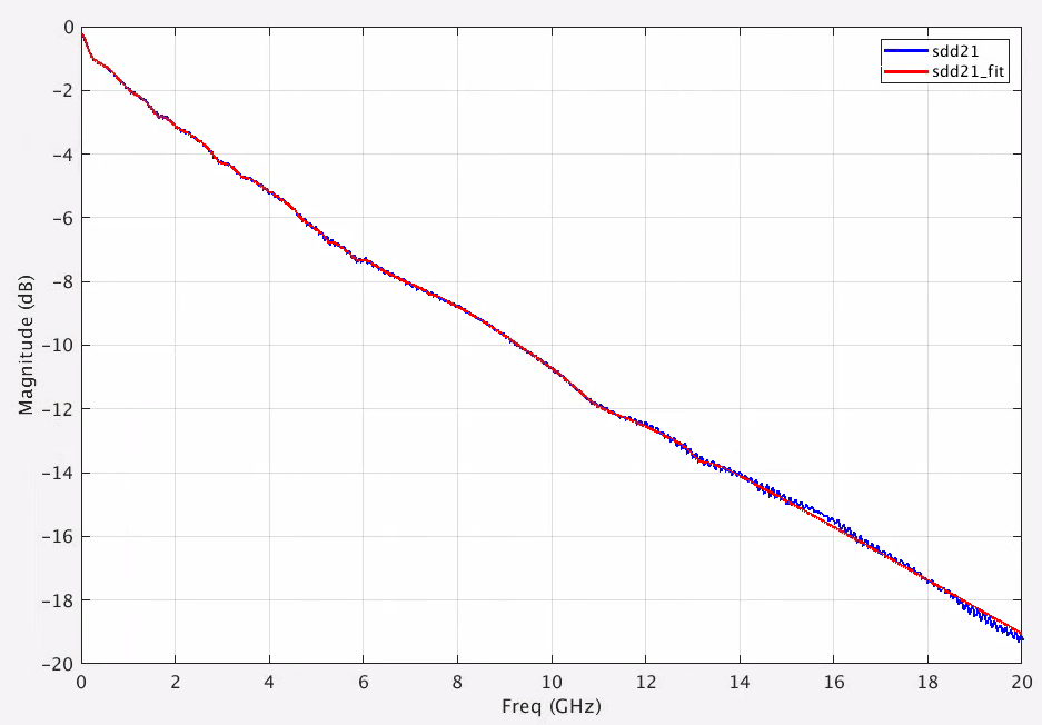
Rational Fit
Use the rational
function to fit data defined in the frequency domain with an equivalent
Laplace transfer function. Using rational function fitting you can
create simple models for a required accuracy, model order reduction,
zero phase on extrapolation to DC, and causal modeling
system among other advantages
1 | filename = 'touchstone/ISI.S4P'; |
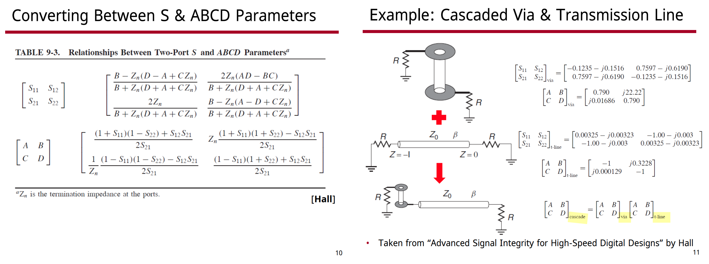
Cascading S-Parameters
Sam Palermo, Lecture 6: S-Parameter Channel Examples [https://people.engr.tamu.edu/spalermo/ecen689/lecture6_ee689_sparam_channels.pdf]
Cascading S-Parameters in Plain English: Part 3: T-Parameters in Plain English [http://thinkinitthrough.com/blogs/details/6]
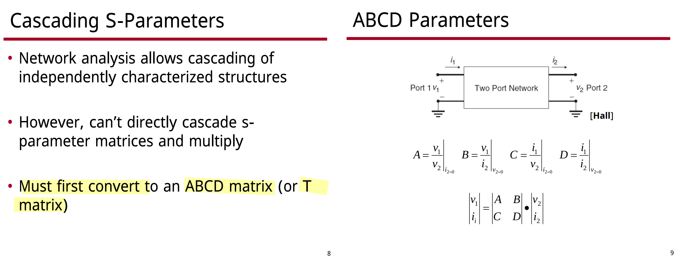
S-parameters by definition require very specific control over the ports. But this breaks down when we chain multiple devices together
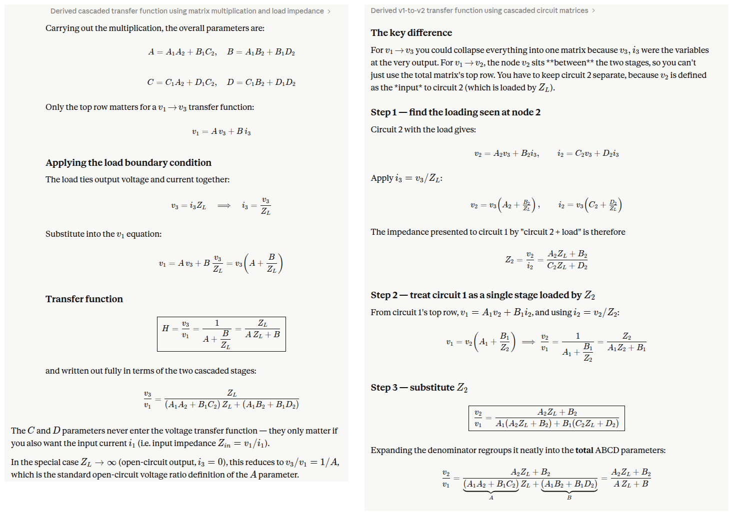
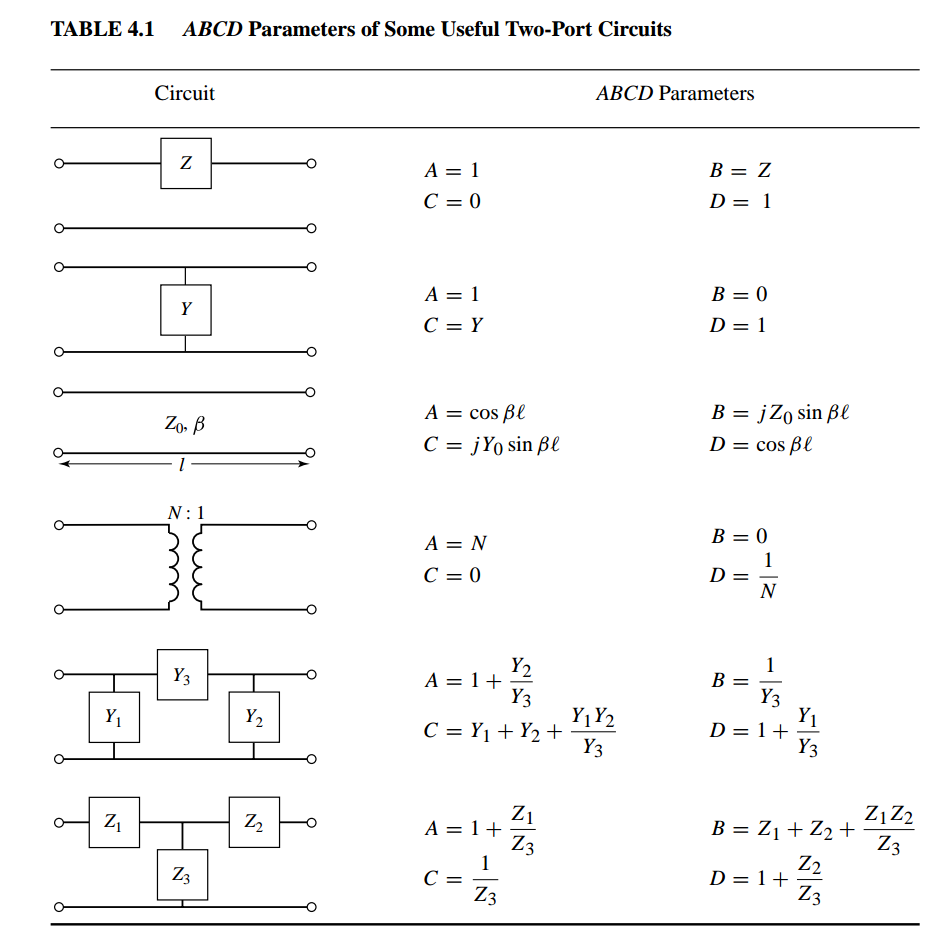
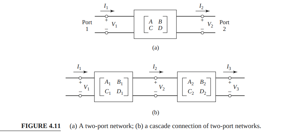
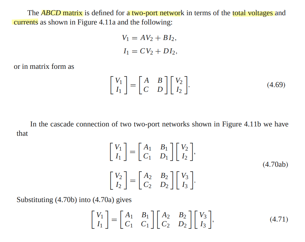
Cascading with ABCD Matrix
aka. transmission matrix
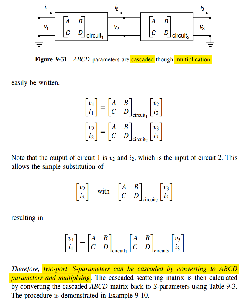
With load impedance \(v_3=i_3 Z_L\), cascade transfer function can be derived
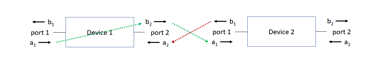
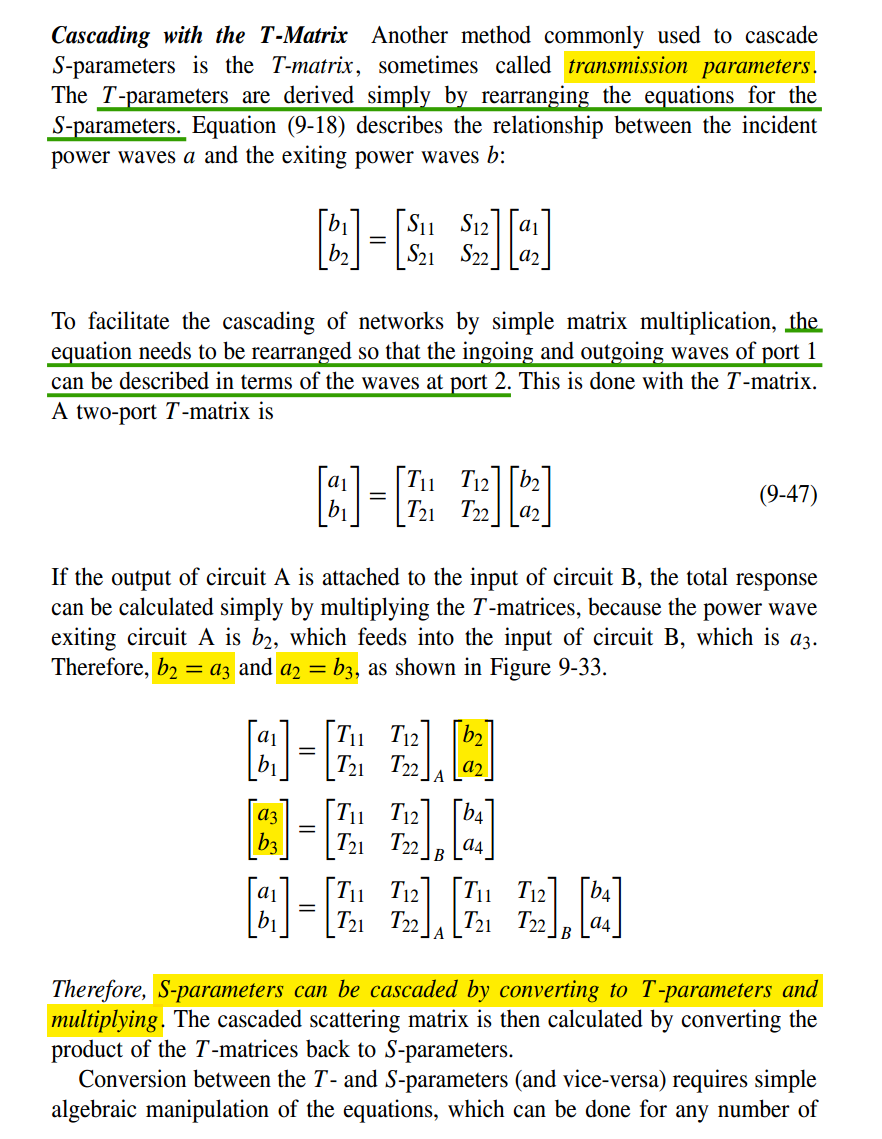
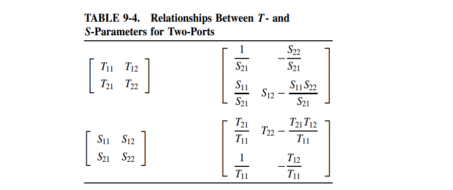
Cascading with T-Matrix
aka. scattering transfer parameters, T-Parameters, transmission parameters
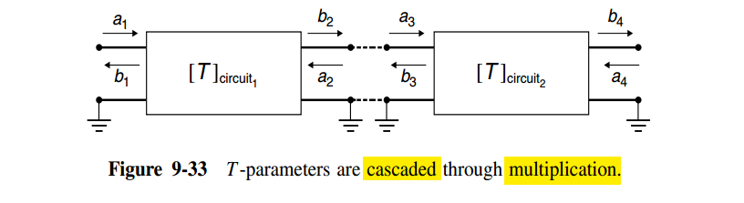
When you cascade two networks by multiplying their T-matrices, you're implicitly assuming that port 2 of network A and port 1 of network B share the same wave definitions
S-parameter Renormalization
[https://swb.skku.edu/emc/infromation.do?mode=download&articleNo=21913&attachNo=19783]
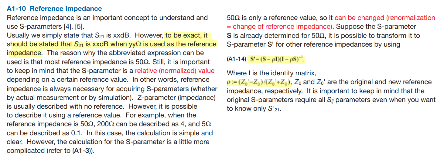
Gustavo Blando, S-parameter Renormalization, The Art of Cheating [https://www.signalintegrityjournal.com/articles/270-s-parameter-renormalization-the-art-of-cheating]
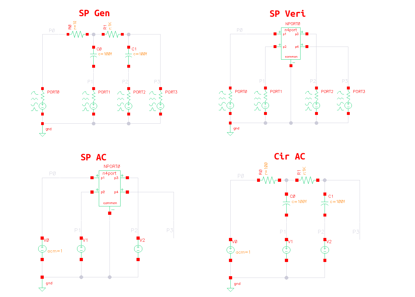
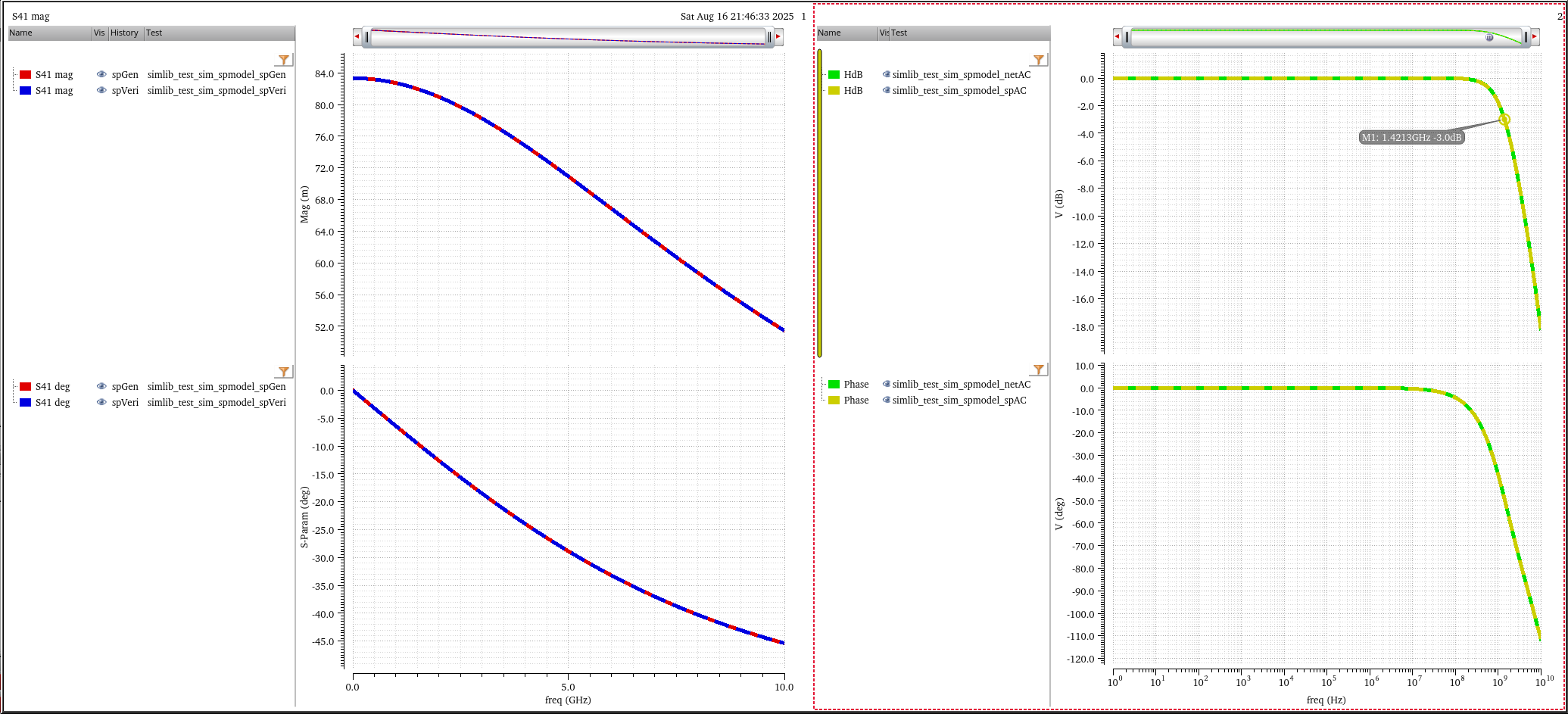
Spar in Tran simulation
Spar in AC simulation
reference
Bogatin, E. (2018). Signal and power integrity, simplified. Prentice Hall. [pdf]
Oh, Kyung, and Xing Yuan. High-Speed Signaling: Jitter Modeling, Analysis, and Budgeting. 1st edition. Prentice Hall, 2011. [pdf]
Pupalaikis, P. (2020). S-Parameters for Signal Integrity. Cambridge: Cambridge University Press.
microwaves101, S-parameters (https://www.microwaves101.com/encyclopedias/s-parameters)
Coelho, C. P., Phillips, J. R., & Silveira, L. M. (n.d.). Robust rational function approximation algorithm for model generation. Proceedings 1999 Design Automation Conference (Cat. No. 99CH36361). [https://sci-hub.ru/10.1109/dac.1999.781313]
Cadence IEEE IMS 2023, Introducing the Spectre S-Parameter Quality Checker and Rational Fit Model Generator
The Complex Art Of Handling S-Parameters: The importance of extraction and fitting to circuit simulation involving S-parameters [https://semiengineering.com/the-complex-art-of-handling-s-parameters]
Dr. John Choma. EE 541, Fall 2006: Course Notes #2 Scattering Parameters: Concept, Theory, and Applications [https://www.ieee.li/pdf/essay/scattering_parameters_concept_theory_applications.pdf]
Dr. Ray Kwok . Network Techniques: Conversion between Filter Transfer Function and Filter Scattering (SMatrix) Parameters [https://www.sjsu.edu/people/raymond.kwok/docs/project172/FTF%20to%20S-Matrix%20Spring%202011.pdf]
田庆诚教授 台湾中华大学 射频电路基础(公司培训)[https://www.bilibili.com/video/BV1LA41177wr/?p=3&share_source=copy_web&vd_source=5a095c2d604a5d4392ea78fa2bbc7249]