JTAG and Boundary Scan
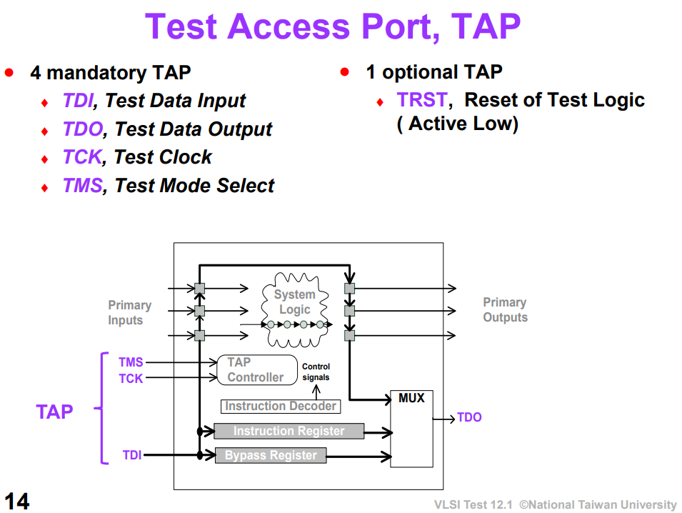
Data Register, DR:
- Bypass Register, BR
- Boundary Scan Register, BSR
Instruction Register, IR
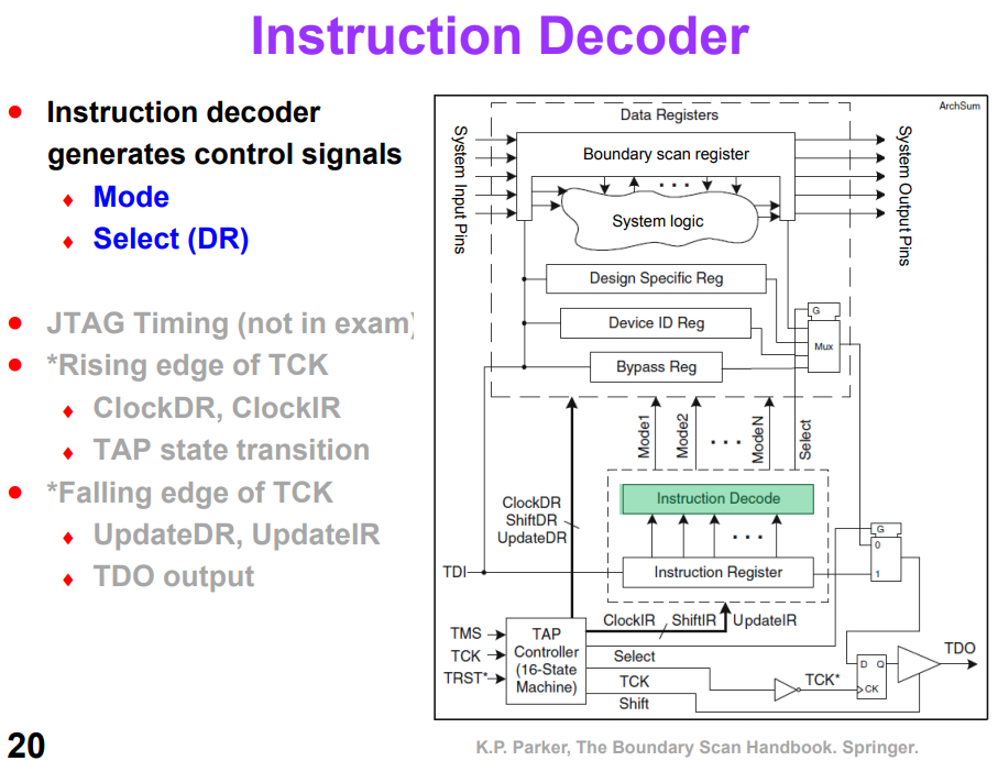
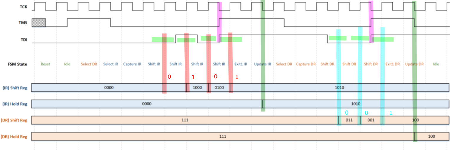
TAP Controller
- FSM and Shift Register of DR and IR works at the posedge of the clock
- TMS, TDI, TDO and Hold Register of DR and IR changes value at the negedge of the clock
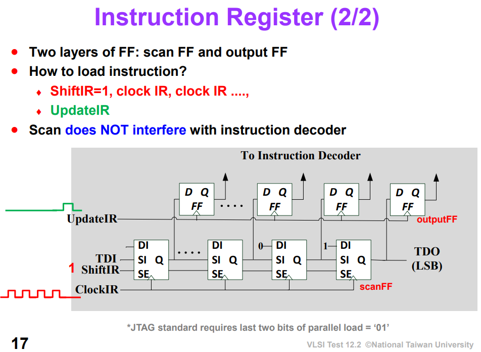
capture IR
01, the fixed is for easier fault detection
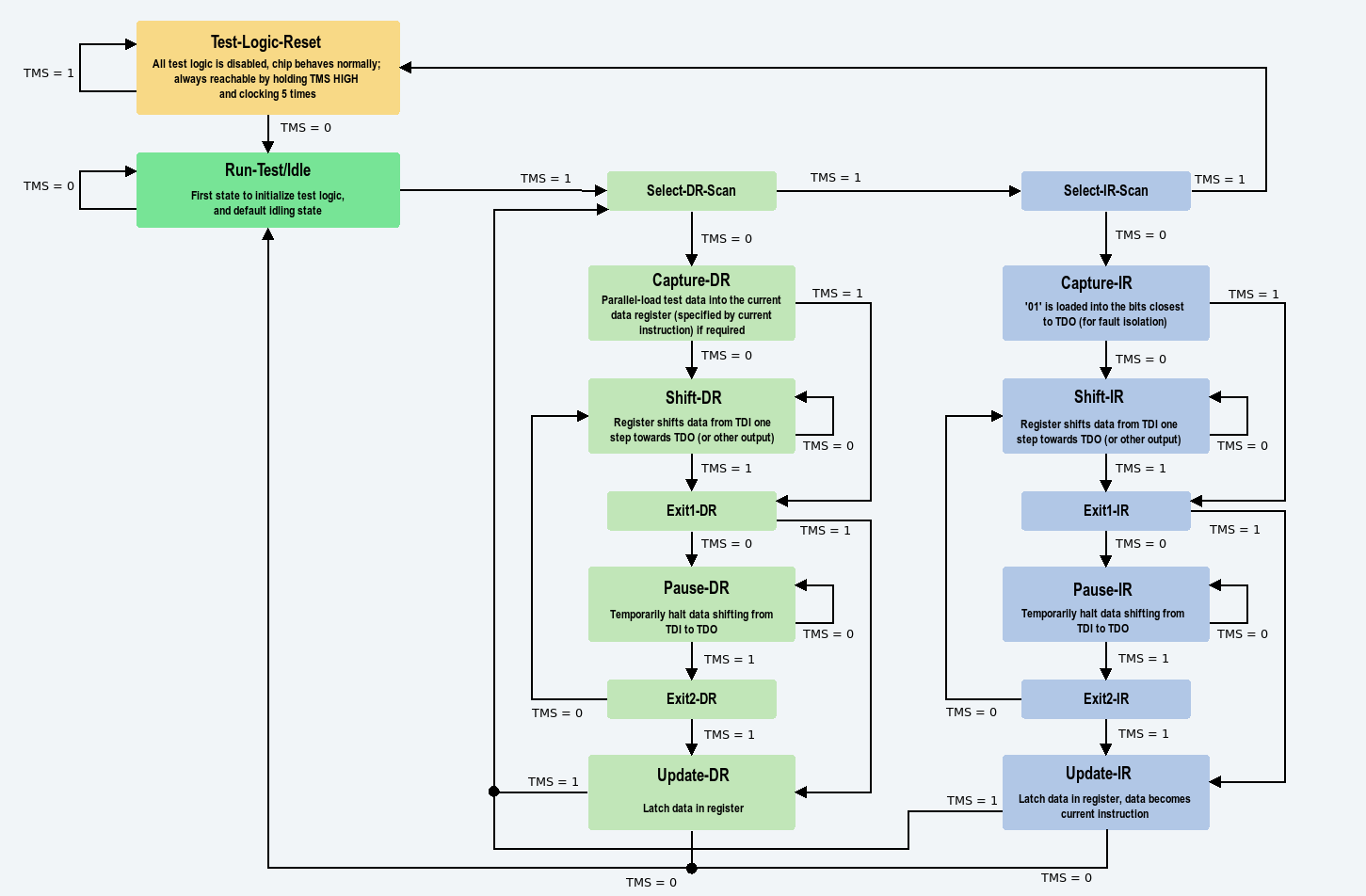
After power-up, they may not be in sync, but there is a trick. Look at the state machine and notice that no matter what state you are, if TMS stays at "1" for five clocks, a TAP controller goes back to the state "Test-Logic Reset". That's used to synchronize the TAP controllers.
It is important to note that in a typical Boundary-Scan test, the time between launching a signal from driver (at the falling edge of test clock (TCK) in the
Update-DRorUpdate-IRTAP Controller state) and capturing that signal (at the rising edge of TCK in theCaputre-DRTAP Controller state) is no less tha 2.5 TCK cycles
Further, the time between successive launches on a driver is governed - not only by the TCk rate - but by the amount of serial data shifting needed to load the next pattern data in the concatenated Boundary-Scan Registers of the Boundary-Scan chain
Thus the effective test data rate of a driver could be thousands of the times lower than the TCK rate
- For DC-coupled interconnect, this time is of no concern
- For AC-coupled interconnect, the signal may easily decay partially or completely before it can be captured
- If only partial decay occurs before capture, that decay will very likely be completed before the driver produces the next edge
AC-coupling
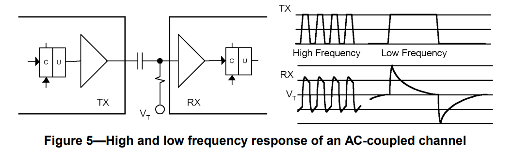
In general, AC-coupling can distort a signal transmitted across a channel depending on its frequency.
Figure 5
- The high frequency signal is relatively unaffected by the coupling
- The low frequency signal is severely impacted
- it decays to \(V_T\) after a few time constants
- its amplitude is double the input amplitude > transient response, before AC-coupling capacitor: \(-A_p \to A_p\); after AC-coupling capacitor \(V_T \to V_T+2A_p\) > A key item to note is that the transitions in the original signal are preserved, although their start and end points are offset > > compared to where they were in the high frequency
Test signal implementation
The test data is either the content of the Boundary-Scan Register Update latch (U) when executing the (DC) EXTEST instruction, or an "AC Signal" when an AC testing instruction is loaded into the device.
The AC signal is a test waveform suited for transmission through AC-coupling
Test signal reception
- When an AC testing instruction is loaded, a specialized test receiver detects transitoins of the AC signal seen at the input and determines if this represents a logic '0' or '1'
- When EXTEST is loaded, the input signal level is detected and sent to the output of the test receiver to the Boundary-Scan Register cell
When testing for a shorted capacitor, the test software must ensure that enough time has passed for the signal to decay before entering Capture-DR, either by stopping TCk or by spending additional TCK cycles in the Run-Test/Idle TAP Controller state
EXTEST_PULSE & EXTEST_TRAIN
The two new AC-test instructions provided by this standard differ primarily in the number and timing of transitions to provide flexibility in dealing with the specific dynamic behavior of the channels being tested
AC Test Signal essentially modulates test data so that it will propagate through AC-coupled channels, for devices that contatin AC pins
Tools should use the EXTEST_PULSE instruction unless there is a specific requirement for the EXTEST_TRAIN instruction
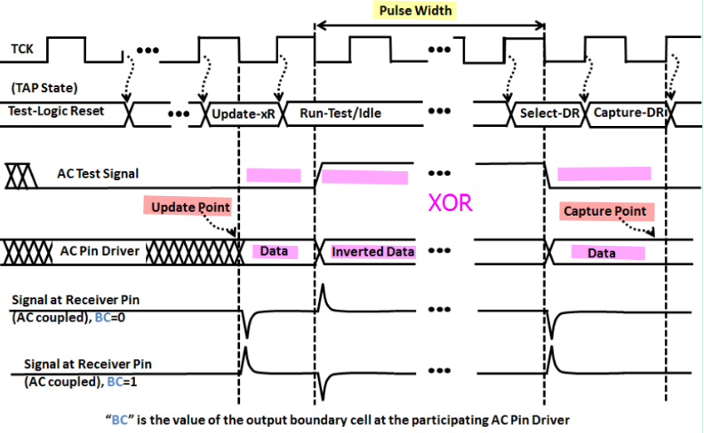
EXTEST_PULSE
Generate two additional driver transitions and allows a tester to vary the time between them dependent on how many TCK cycles the TAP is left in the Run-Test/Idle TAP Controller state.
This is intended to allow any undesired transient condition to decay to a DC steady-state value when that will make the final transition more reliably detectable
The duration in the Run-Test/Idle TAP Controller state should be at least three times the high-pass coupling time constant. This allows the first additional transition to decay away to the DC steady-state value for the channel, and ensures that the full amplitude of the final transition is added to or subtracted from that steady-state value
This establishes a known initial condition for the final transition and permits reliable specification of the detection threshold of the test receiver
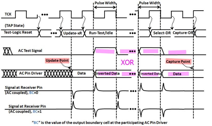
EXTEST_TRAIN
Generate multiple additional transitions, the number dependent on how long the TAP is left in the Run-Test/Idle TAP Controller state
This is intended to allow any undesired transient condition to decay to an AC steady-state value when that will make the final transition more reliably detectable
IEEE Std 1149.6-2003
This standard is built on top of IEEE Std 1149.1 using the same Test Access Port structure and Boundary-Scan architecture.
- It adds the concept of a "test receiver" to input pins that are expected to handle differential and/or AC-coupling
- It adds two new instructions that cause drivers to emit AC waveforms that are processed by test receivers.
JTAG Instruction
Implementation
- AC mode hysteresis, detect transistion
- DC mode threshold is determined by jtag initial value
reference
IEEE Std 1149.1-2001, IEEE Standard Test Access Port and Boundary-Scan Architecture, IEEE, 2001
IEEE Std 1149.6-2003, IEEE Standard for BoundaryScan Testing of Advanced Digital Networks, IEEE, 2003
IEEE 1149.6 Tutorial | Testing AC-coupled and Differential High-speed Nets [https://www.asset-intertech.com/resources/eresources/ieee-11496-tutorial-testing-ac-coupled-and-differential-high-speed-nets/]
Prof. James Chien-Mo Li, Lab of Dependable Systems, National Taiwan University. VLSI Testing [http://cc.ee.ntu.edu.tw/~cmli/VLSItesting/]
K.P. Parker, The Boundary Scan Handbook, 3rd ed., Kluwer Academic, 2003.
B. Eklow, K. P. Parker and C. F. Barnhart, "IEEE 1149.6: a boundary-scan standard for advanced digital networks," in IEEE Design & Test of Computers, vol. 20, no. 5, pp. 76-83, Sept.-Oct. 2003, doi: 10.1109/MDT.2003.1232259.