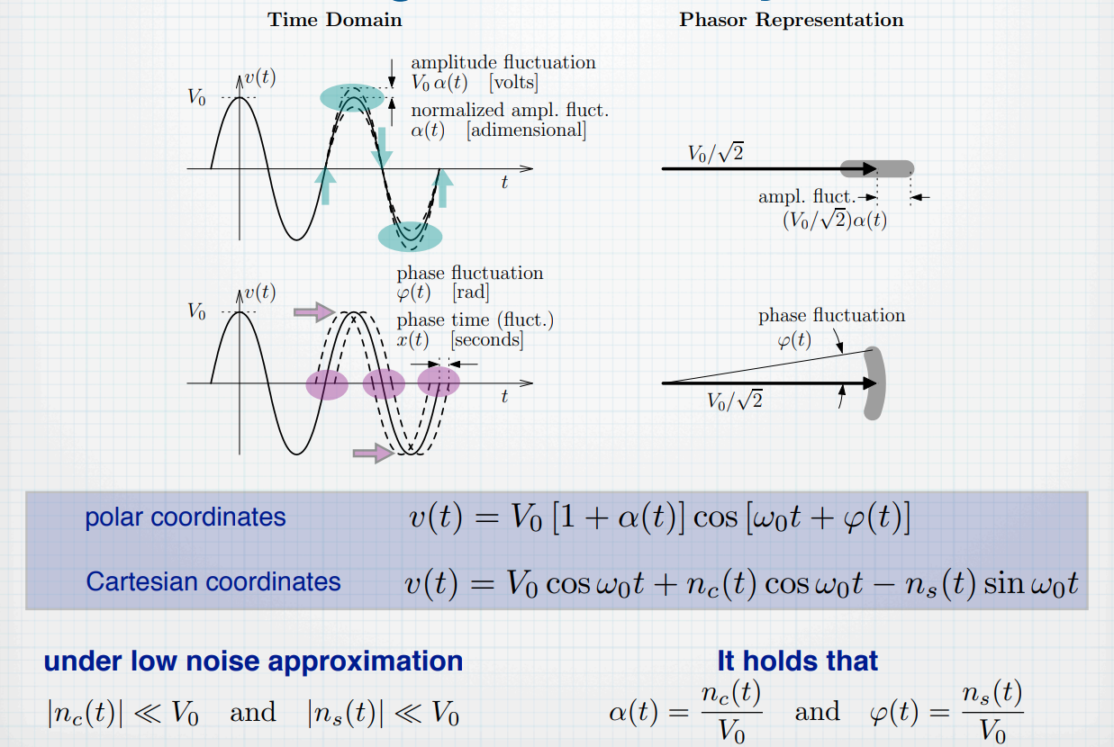
AM & PM
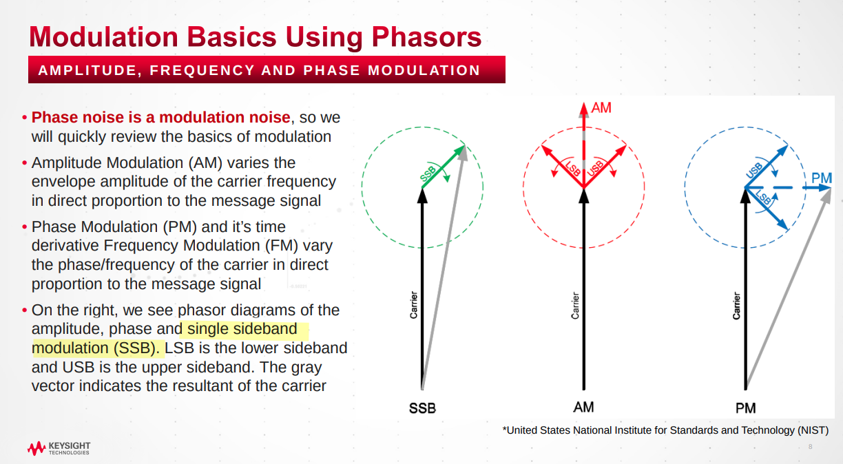
Phasor Diagram
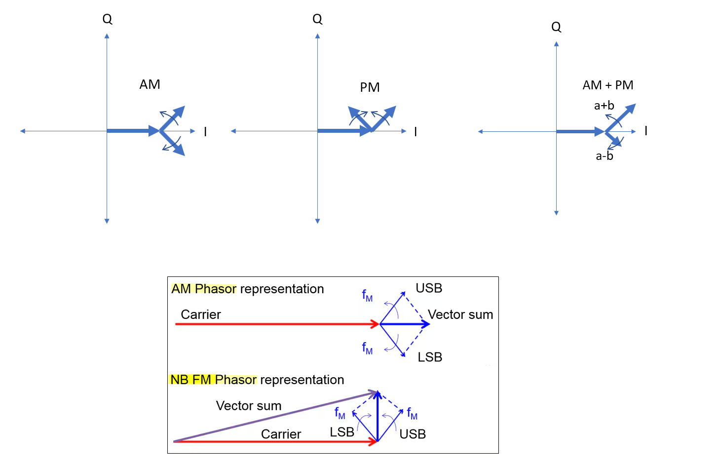
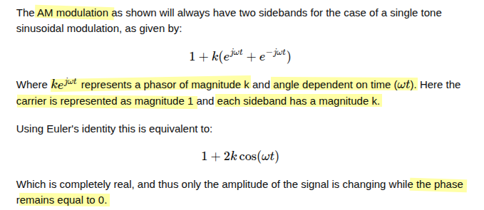
"I" is the in-phase or real axis and "Q" is the quadrature or imaginary axis
phasor rotating counter-clockwise represents the upper sideband (USB) \(e^{j(\omega_o+\omega_m )t} = e^{j\omega_o t}\color{red}e^{j\omega_m t}\)
phasor rotating clockwise represents the lower sideband (LSB) \(e^{j(\omega_o-\omega_m )t} = e^{j\omega_o t}\color{red}e^{-j\omega_m t}\)
AM modulation
 \[\begin{align}
x(t)&= (1+2k\cos(\omega_m t)) \cos(\omega_0 t) \\
& = \cos(\omega_0 t) + 2k \cos(\omega_m t) \cos(\omega_0 t) \\
&=\mathcal{Re}\{e^{j\omega_0t}+k(e^{j\omega_0t}e^{j\omega_mt}+e^{j\omega_0t}e^{-j\omega_mt})\}\\
&=\mathcal{Re}\{e^{j\omega_0t}(\color{red}1+k(e^{j\omega_mt}+e^{-j\omega_mt})\color{black})\}
\end{align}\]
\[\begin{align}
x(t)&= (1+2k\cos(\omega_m t)) \cos(\omega_0 t) \\
& = \cos(\omega_0 t) + 2k \cos(\omega_m t) \cos(\omega_0 t) \\
&=\mathcal{Re}\{e^{j\omega_0t}+k(e^{j\omega_0t}e^{j\omega_mt}+e^{j\omega_0t}e^{-j\omega_mt})\}\\
&=\mathcal{Re}\{e^{j\omega_0t}(\color{red}1+k(e^{j\omega_mt}+e^{-j\omega_mt})\color{black})\}
\end{align}\]
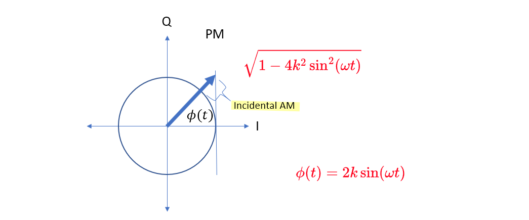
PM modulation with incidental AM

A. A. Abidi and D. Murphy, "How to Design a Differential CMOS LC Oscillator," in IEEE Open Journal of the Solid-State Circuits Society, vol. 5, pp. 45-59, 2025, doi: 10.1109/OJSSCS.2024 [pdf]
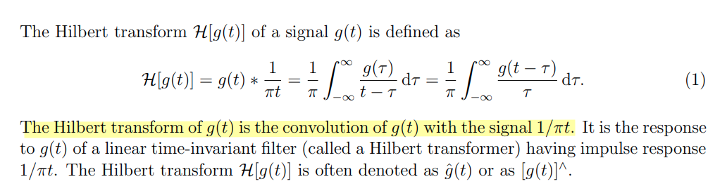
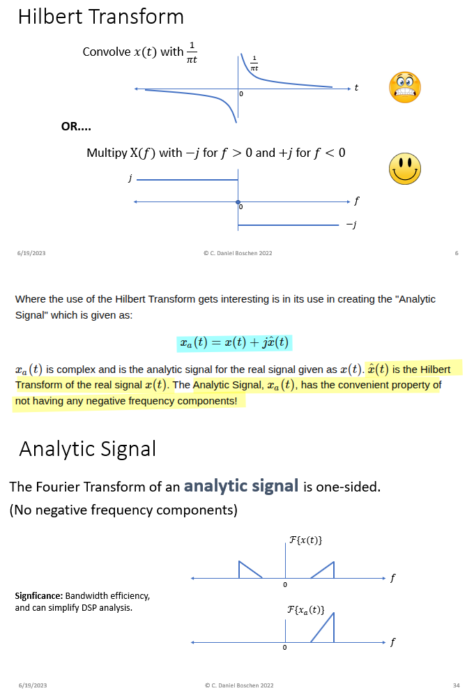
Analytic Signal & Hilbert Transform
Mathuranathan. Understanding Analytic Signal and Hilbert Transform [https://www.gaussianwaves.com/2017/04/analytic-signal-hilbert-transform-and-fft/]
Dan Boschen. What information does the Hilbert transform give? [https://dsp.stackexchange.com/a/88292/59253]
Frank R. Kschischang. The Hilbert Transform [https://www.comm.utoronto.ca/frank/notes/hilbert.pdf]
Interaction with the Fourier Transform
TODO 📅
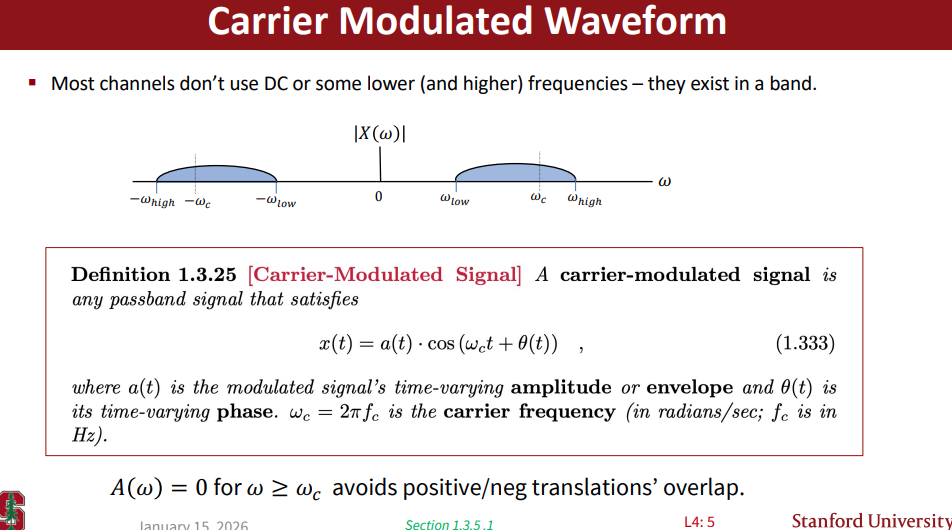
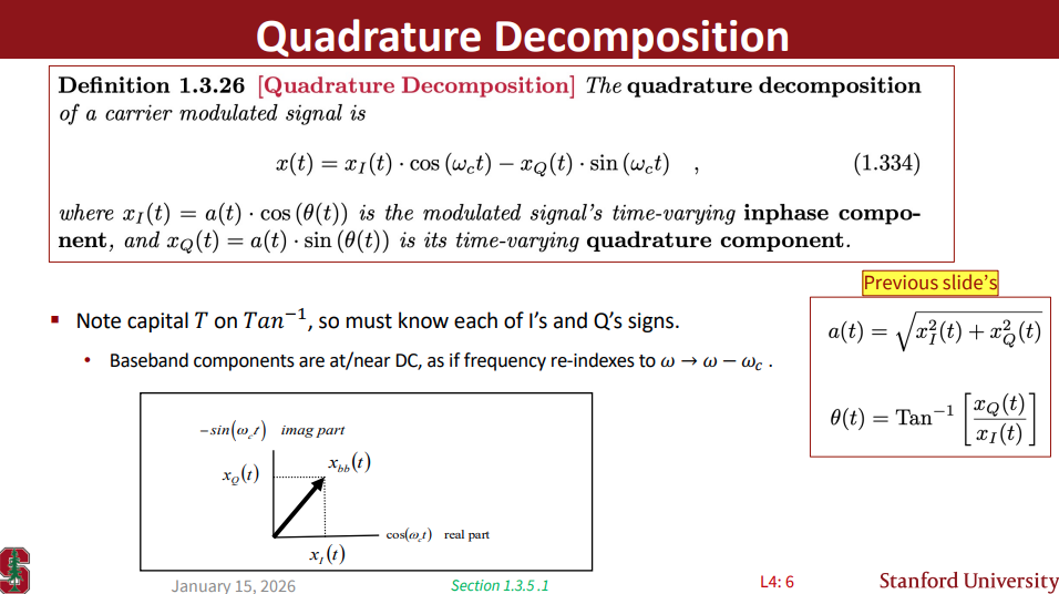
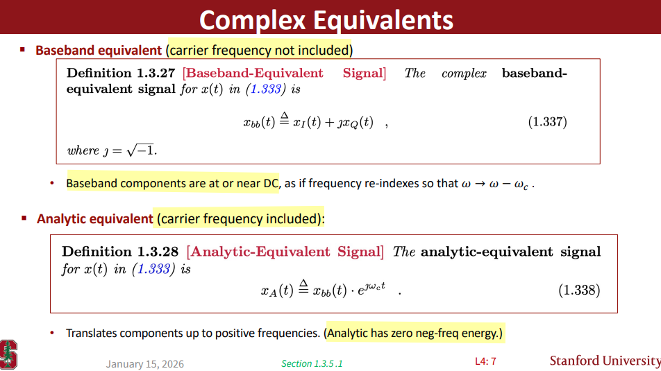
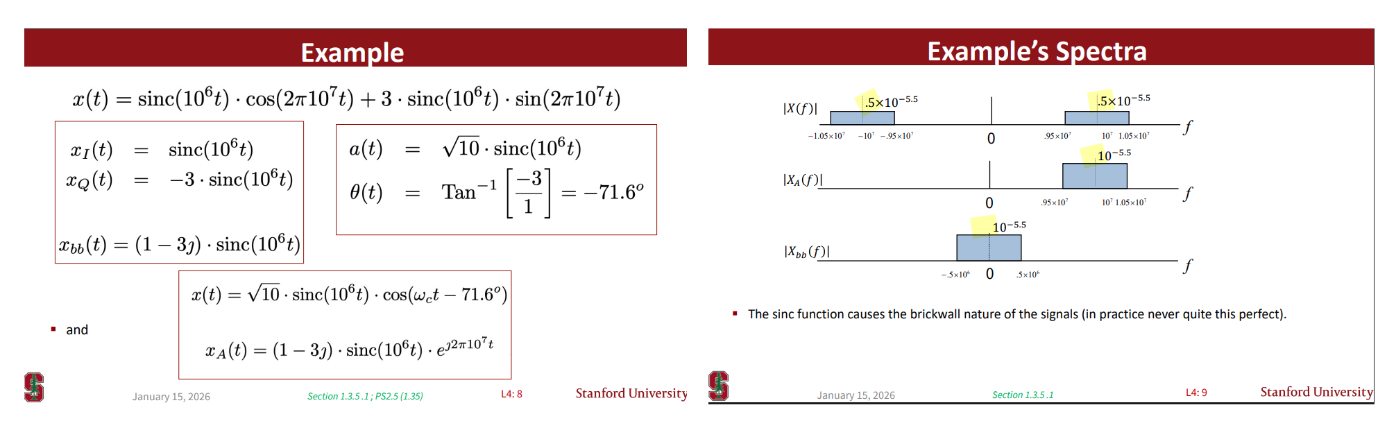
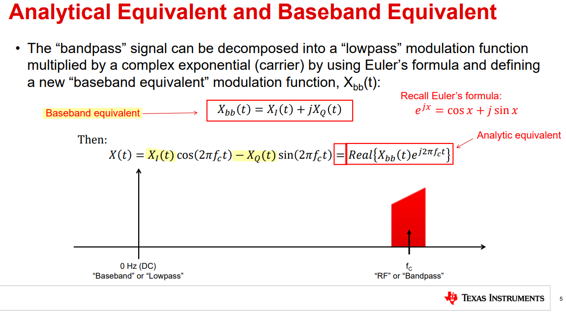
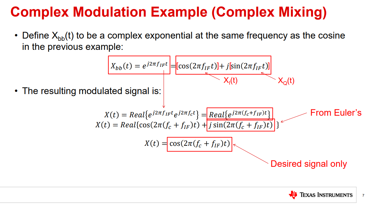
Real & Complex Modulation
J OHN M. C IOFFI. Complex AWGN and Other Channels [https://cioffi-group.stanford.edu/ee379a/Lectures/L4.pdf]
| signal | Spectra |
|---|---|
| \(x_{bb}(t) = x_I(t)+jx_Q(t)\) | \(X_{I}(\omega)+jX_Q(\omega)\) |
| \(x(t)=\color{red}x_I(t)\cdot\cos(\omega_c t)\color{blue}-x_Q(t)\cdot\sin(\omega_c t)\) | \(\color{red}\frac{1}{2}X_{I}(\omega+\omega_c)+\color{blue}\frac{1}{2}jX_{Q}(\omega+\omega_c)+\color{red}\frac{1}{2}X_{I}(\omega-\omega_c)+\color{blue}\frac{1}{2}jX_{Q}(\omega-\omega_c)\) |
| \(x_A=x_{bb}(t)\cdot e^{j\omega_c t}\) | \(X_{I}(\omega-\omega_c)+jX_Q(\omega-\omega_c)\) |
Matt Guibord. TIPL 4: Real and Complex Modulation [https://www.ti.com/content/dam/videos/external-videos/en-us/2/3816841626001/5576277660001.mp4/subassets/TIPL4708-Real-and-Complex-Modulation.pdf]
 \[\begin{align}
X_{bb,AM,USB}(t) &= e^{j\omega_m t} = \cos(\omega_m t) +
j\sin(\omega_m t)\\
X_{bb,AM,LSB}(t) &= e^{-j\omega_m t} = \cos(\omega_m t) -
j\sin(\omega_m t)
\end{align}\]
\[\begin{align}
X_{bb,AM,USB}(t) &= e^{j\omega_m t} = \cos(\omega_m t) +
j\sin(\omega_m t)\\
X_{bb,AM,LSB}(t) &= e^{-j\omega_m t} = \cos(\omega_m t) -
j\sin(\omega_m t)
\end{align}\]
where \(X_{I,AM,USB}(t)=\cos(\omega_m t)\) and \(X_{Q,AM,USB}(t)=\sin(\omega_m t)\); \(X_{I,AM,USB}(t)=\cos(\omega_m t)\) and \(X_{Q,AM,USB}(t)=-\sin(\omega_m t)\);
\(X_{I,AM,USB} = X_{I,AM,LSB}\) and \(X_{Q,AM,USB} = -X_{Q,AM,LSB}\)
\[\begin{align} X_{bb,PM,USB}(t) &= e^{j\omega_m t} = \cos(\omega_m t) + j\sin(\omega_m t)\\ X_{bb,PM,LSB}(t) &= -e^{-j\omega_m t} = -\cos(\omega_m t) + j\sin(\omega_m t) \end{align}\]
where \(X_{I,PM,USB}(t)=\cos(\omega_m t)\) and \(X_{Q,PM,USB}(t)=\sin(\omega_m t)\); \(X_{I,PM,USB}(t)=-\cos(\omega_m t)\) and \(X_{Q,PM,USB}(t)=\sin(\omega_m t)\);
\(X_{I,PM,USB} = -X_{I,PM,LSB}\) and \(X_{Q,PM,USB} = X_{Q,PM,LSB}\)
Amplitude Noise
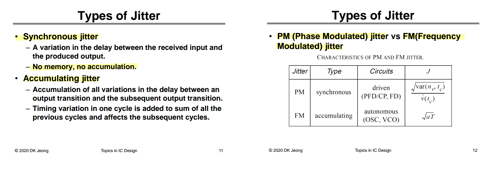
Deog-Kyoon Jeong. Topics in IC Design: 1.1 Introduction to Jitter [https://ocw.snu.ac.kr/sites/default/files/NOTE/Lec%201%20-%20Jitter%20and%20Phase%20Noise.pdf]
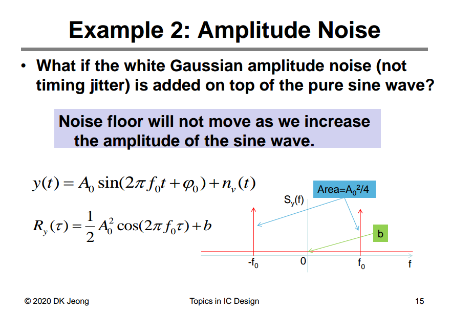
with \(x(t) = A_0\sin (2\pi f_0 t +\phi _0)\), then \(y(t) = x(t) + n_v(t)\)
\[\begin{align} R_y(\tau) &= \mathrm{E}[y(t)y(t+\tau)] \\ &= \mathrm{E}[x(t)x(t+\tau)] + \mathrm{E}[x(t)]\mathrm{E}[n_v(t+\tau)] + \mathrm{E}[x(t+\tau)]\mathrm{E}[n_v(t)] + \mathrm{E}[n_v(t)n_v(t+\tau)]\\ &= \mathrm{E}[x(t)x(t+\tau)] + \mathrm{E}[n_v(t)n_v(t+\tau)] \\ &= R_x(\tau) + R_{n_v}(\tau) \end{align}\]
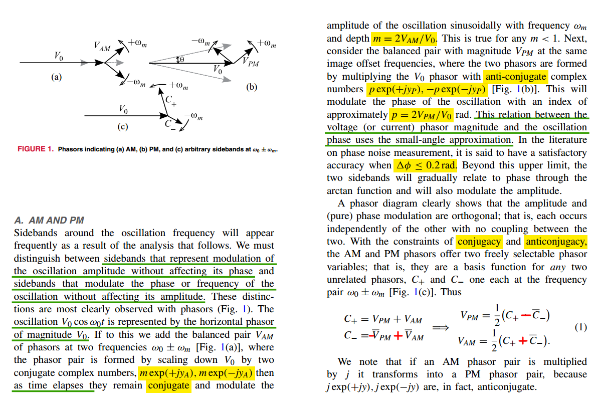
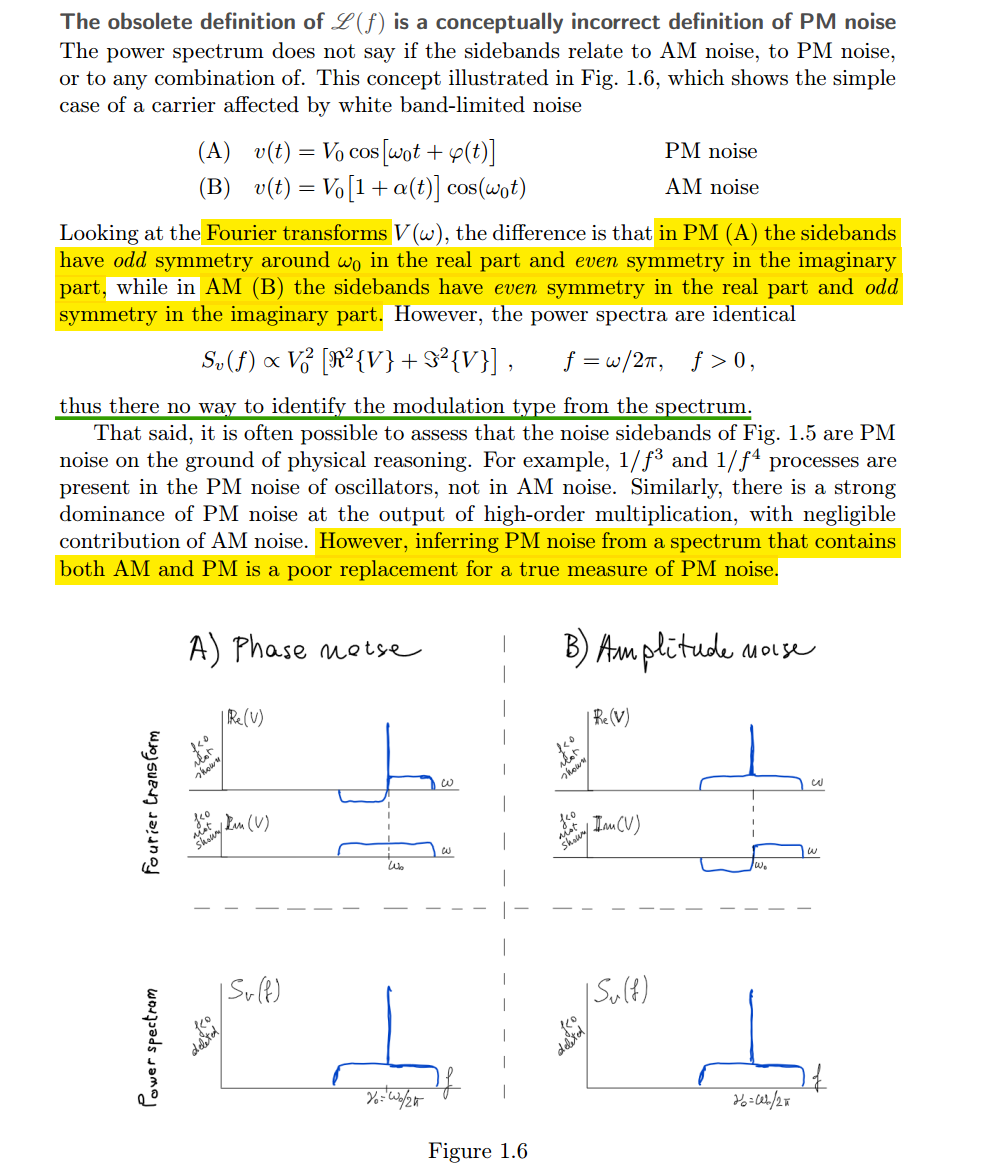
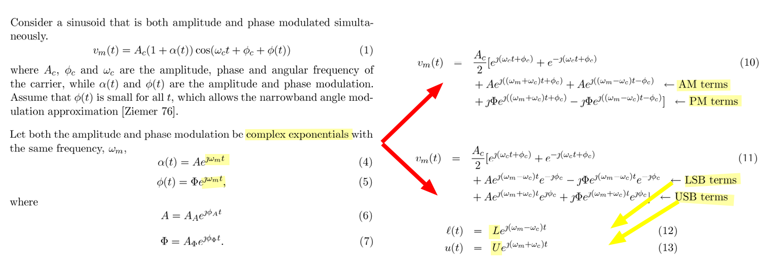
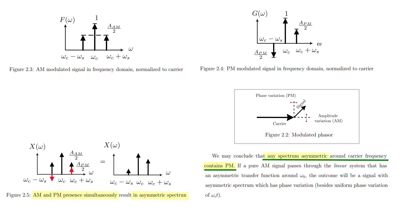
AM & PM Sidebands
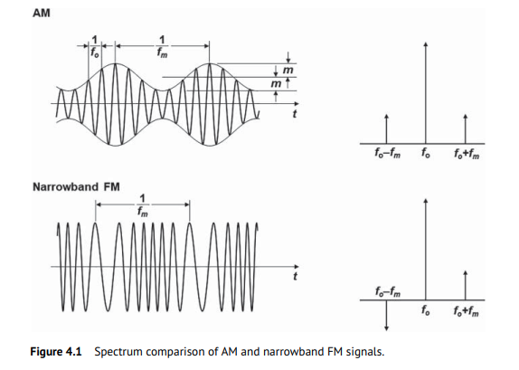
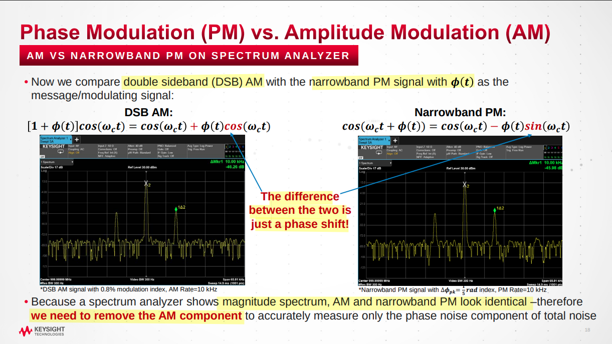
The spectrum of the narrowband FM signal is very similar to that of an amplitude modulation (AM) signal but has the phase reversal for the other sideband component
Assume the modulation frequency of PM and AM are same, \(\omega_m\)
\[\begin{align} x(t) &= (1+A_m\cos{\omega_m t})\cos(\omega_0 t + P_m \sin\omega_m t) \\ &= \cos(\omega_0 t + P_m \sin\omega_m t) + A_m\cos{\omega_m t}\cos(\omega_0 t + P_m \sin\omega_m t) \\ &= X_{pm}(t) + X_{apm}(t) \end{align}\]
\(X_{pm}(t)\), PM Only \[ X_{pm}(t) = \cos\omega_0 t - \frac{P_m}{2}\cos(\omega_0 - \omega_m)t + \frac{P_m}{2}\cos(\omega_0 + \omega_m)t \] \(X_{apm}(t)\), AM & PM \[\begin{align} X_{apm}(t) &= A_m \cos{\omega_m t} (\cos\omega_0 t-P_m\sin\omega_m t\sin\omega_0 t) \\ &= \frac{A_m}{2}[\cos(\omega_0 + \omega_m)t + \cos(\omega_0 -\omega_m)t] - \frac{A_mP_m}{2}\sin(2\omega_m t)\sin(\omega_0 t) \\ &= \frac{A_m}{2}\cos(\omega_0 + \omega_m)t + \frac{A_m}{2}\cos(\omega_0 -\omega_m)t - \frac{A_mP_m}{4}\cos(\omega_0 - 2\omega_m)t + \frac{A_mP_m}{4}\cos(\omega_0 + 2\omega_m)t \end{align}\]
That is \[\begin{align} x(t) &= \cos\omega_0 t + \frac{A_m-P_m}{2}\cos(\omega_0 - \omega_m)t + \frac{A_m+P_m}{2}\cos(\omega_0 + \omega_m)t \\ &\space\space\space\space\space\space\space\space\space\space\space\space\space\space\space\space\space\space - \frac{A_mP_m}{4}\cos(\omega_0 - 2\omega_m)t + \frac{A_mP_m}{4}\cos(\omega_0 + 2\omega_m)t \end{align}\]
For general case, \(x(t) = (1+A_m\cos{\omega_{am} t})\cos(\omega_0 t + P_m \sin\omega_{pm} t)\), i.e., PM is \(\omega_{pm}\), AM is \(\omega_{am}\)
\[\begin{align} x(t) &= \cos\omega_0 t - \frac{P_m}{2}\cos(\omega_0 - \omega_{pm})t + \frac{P_m}{2}\cos(\omega_0 + \omega_{pm})t \\ &\space\space\space\space\space\space\space\space\space\space\space\space\space\space\space\space\space\space + \frac{A_m}{2}\cos(\omega_0 - \omega_{am})t + \frac{A_m}{2}\cos(\omega_0 + \omega_{am})t \\ &\space\space\space\space\space\space\space\space\space\space\space\space\space\space\space\space\space\space - \frac{A_mP_m}{4}\cos(\omega_0 - \omega_{pm}-\omega_{am})t + \frac{A_mP_m}{4}\cos(\omega_0 + \omega_{pm}+\omega_{am})t \\ &\space\space\space\space\space\space\space\space\space\space\space\space\space\space\space\space\space\space + \frac{A_mP_m}{4}\cos(\omega_0 + \omega_{pm}-\omega_{am})t - \frac{A_mP_m}{4}\cos(\omega_0 - \omega_{pm}+\omega_{am})t \end{align}\]
Therefore, sideband is asymmetric if \(\omega_{pm} = \omega_{am}\) same
Hegazi, Emad, Asad Abidi, and Jacob Rael. The Designer's Guide to High-purity Oscillators. [New York]: Kluwer Academic Publishers, 2005. [pdf]
PSD of Narrowband FM Signal
Chembiyan T. Jitter and Phase Noise in Phase Locked Loops [link]
\[ y(t) = A\cos(2\pi f_0t+\phi_n(t)) \approx A \cos(2\pi f_0 t) - A \phi_n (t)\sin(2\pi f_0 t) \]
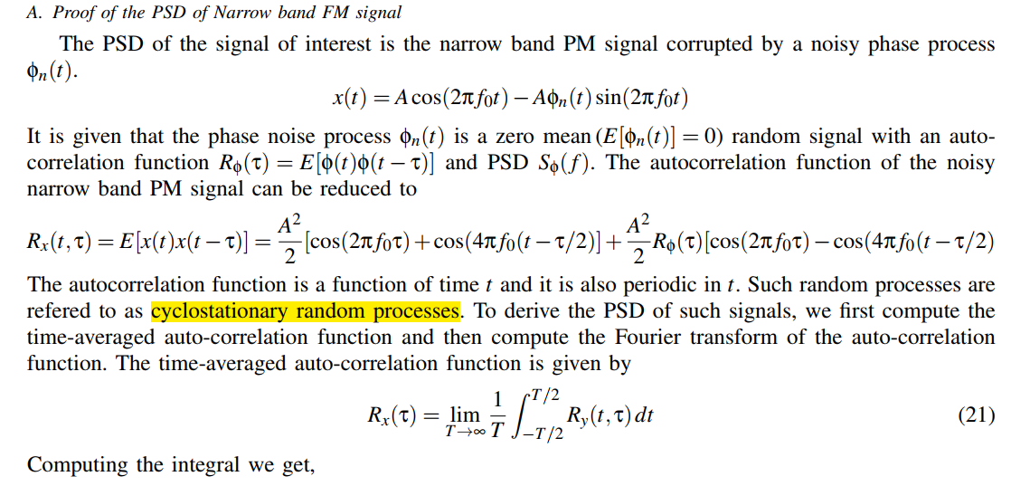 \[
R_x(\tau) = \frac{A^2}{2}\cos(2\pi f_0\tau)
+ \frac{A^2}{2}R_\phi(\tau)\cos(2\pi f_0\tau)
\] The PSD of the signal \(x(t)\) is given by \[
S_x(f) = \mathcal{F}\{R_x(\tau)\} =
\frac{P_c}{2}\left[\delta(f+f_0)+\delta(f-f_0)\right]+\frac{P_c}{2}\left[S_\phi(f+f_0)+S_\phi(f-f_0)\right]
\] where \(P_c = A^2/2\) is the
carrier power of the signal
\[
R_x(\tau) = \frac{A^2}{2}\cos(2\pi f_0\tau)
+ \frac{A^2}{2}R_\phi(\tau)\cos(2\pi f_0\tau)
\] The PSD of the signal \(x(t)\) is given by \[
S_x(f) = \mathcal{F}\{R_x(\tau)\} =
\frac{P_c}{2}\left[\delta(f+f_0)+\delta(f-f_0)\right]+\frac{P_c}{2}\left[S_\phi(f+f_0)+S_\phi(f-f_0)\right]
\] where \(P_c = A^2/2\) is the
carrier power of the signal
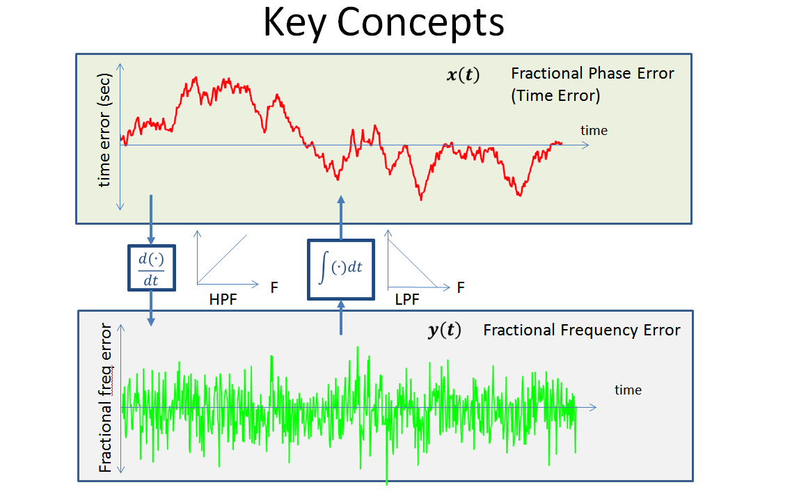
PM & FM
Dan Boschen What is the difference between phase noise and frequency noise? [https://dsp.stackexchange.com/a/38230/59253]
Phase Noise and Frequency Noise are not two different noise sources, they are artifacts of the same noise, it is just a matter of what units you want to use
Equipartition theorem
[https://www.ieeetoronto.ca/wp-content/uploads/2020/06/DL-VCO-short.pdf]
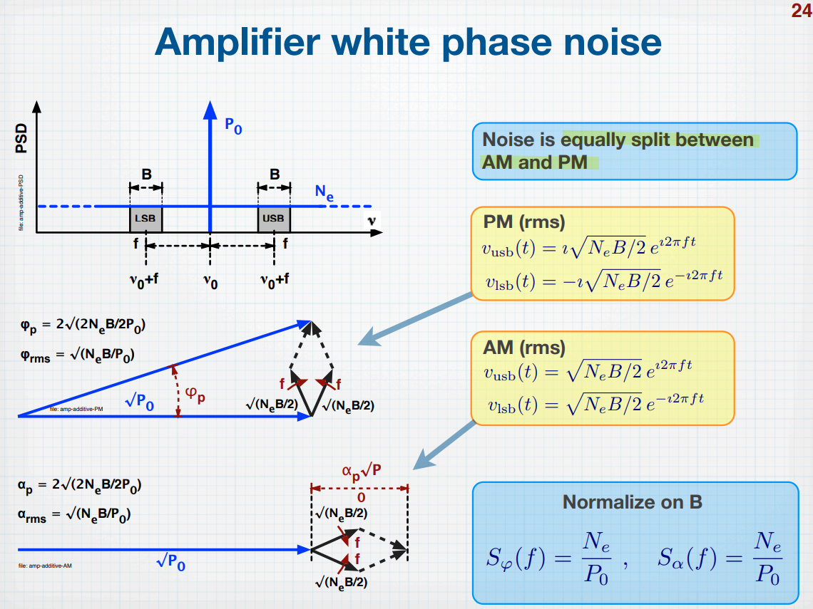
Enrico Rubiola. The Measurement of AM-PM Noise, and the Origin of Noise in Oscillators [https://rubiola.org/pdf-slides/2010T-ANL-Noise-and-oscillators.pdf]
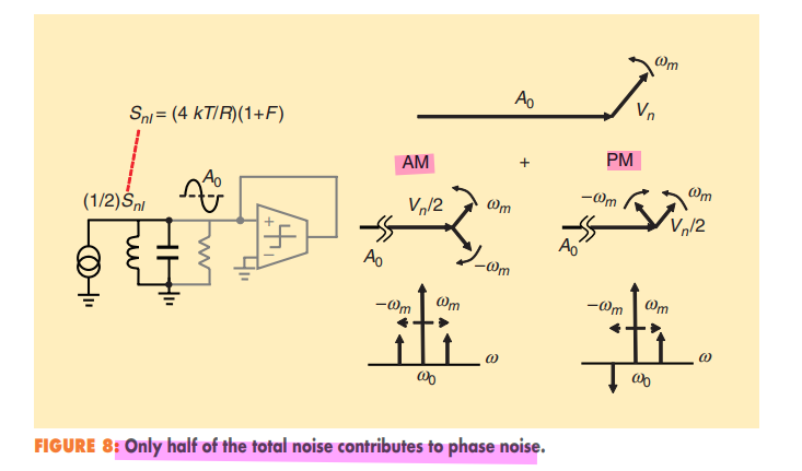
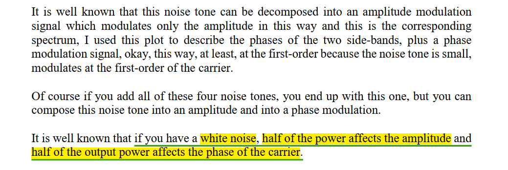
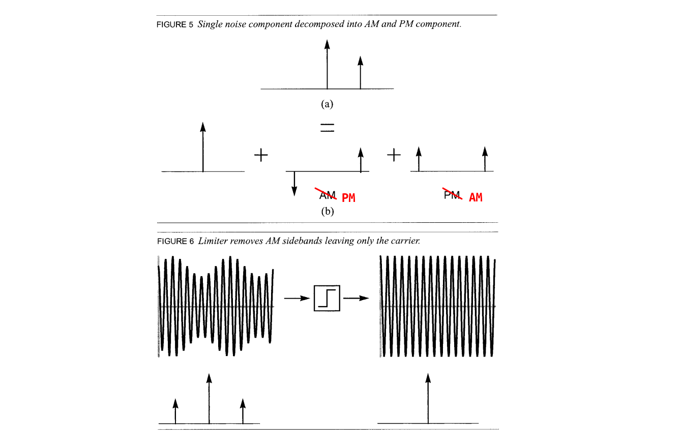
Stationary noise can also be decomposed into AM and PM components, but there will always be equal amounts of both.
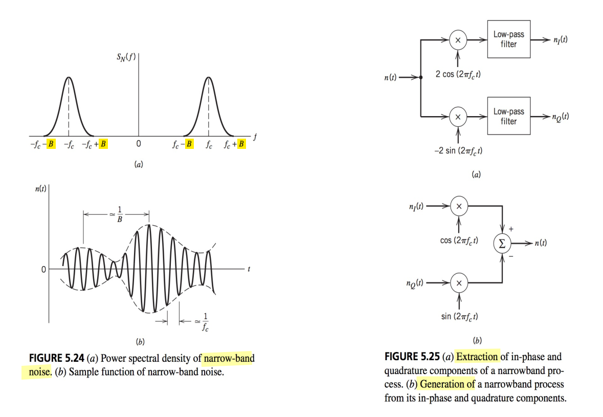
Narrowband Noise

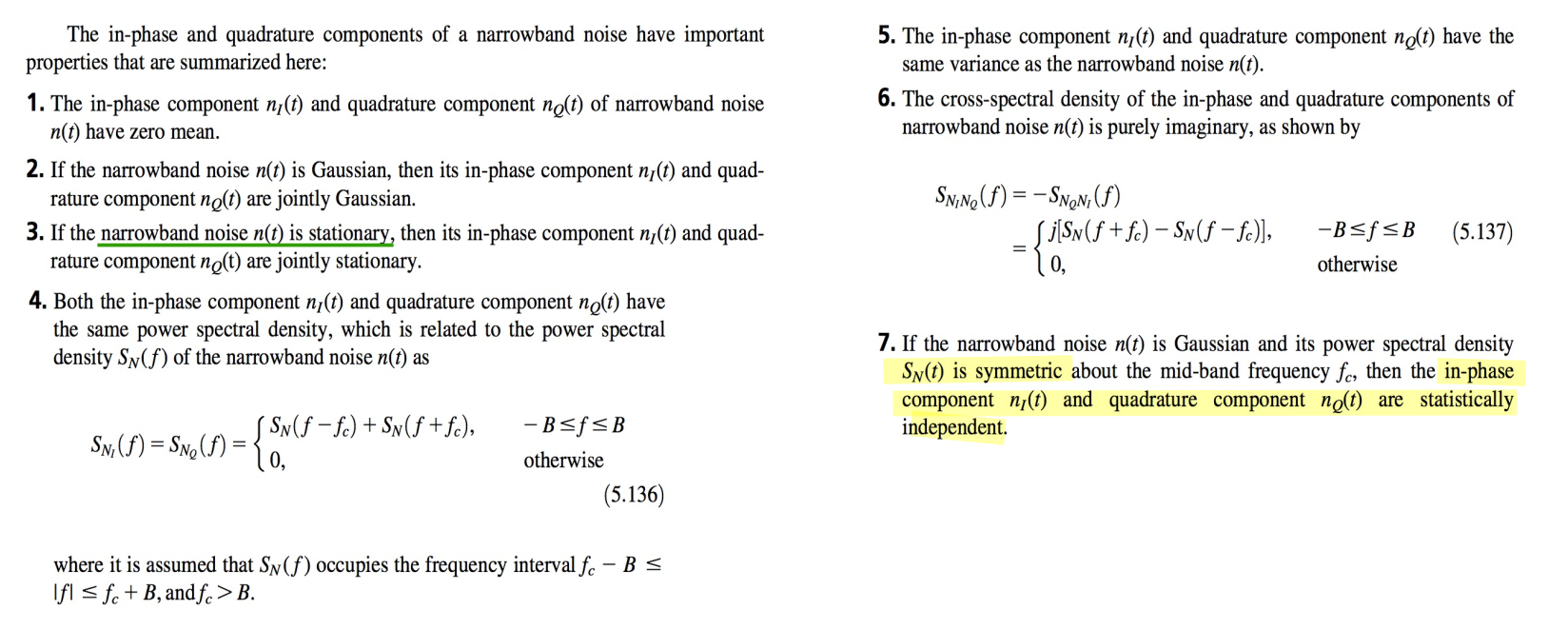
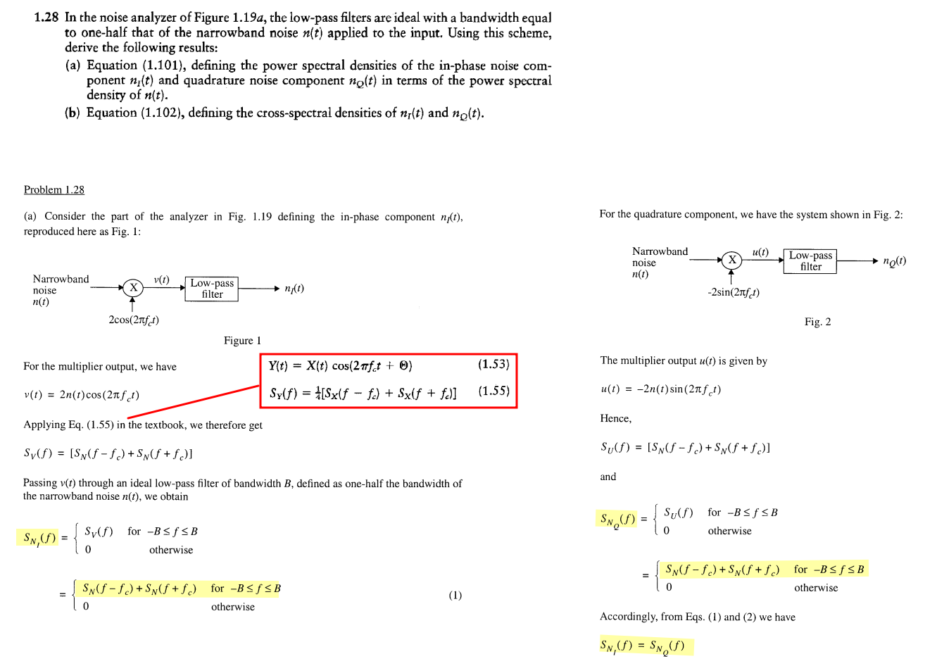
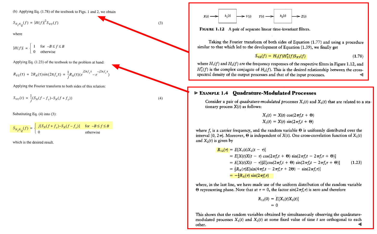
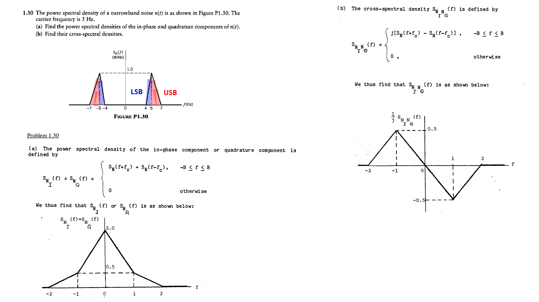
in-phase & quadrature component
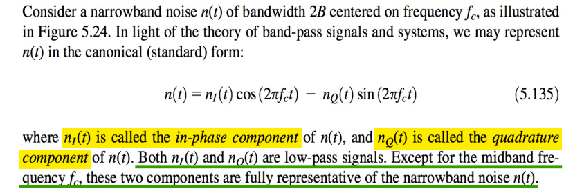
\[\begin{align} n(t)\cdot 2\cos(\omega_c t) &= n_I(t) + n_I(t)\cos(2\omega_c t) - n_Q(t)\sin(2\omega_c t) \\ n(t)\cdot -2\sin(\omega_c t) &= n_Q(t) - n_I(t)\sin(2\omega_c t) - n_Q(t)\cos(2\omega_c t) \end{align}\]

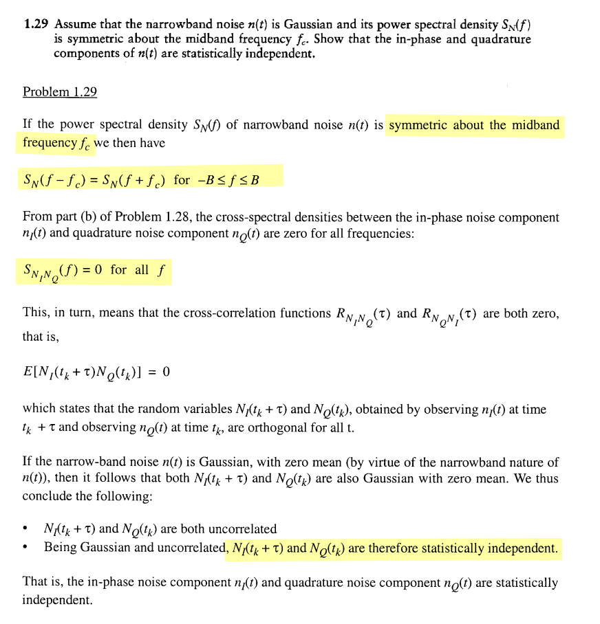
If the narrowband noise \(n(t)\) is Gaussian and its power spectral density \(S_N (t )\) is symmetric about the mid-band frequency \(f_c\), then the in-phase component \(n_I(t)\) and quadrature component \(n_Q(t)\) are statistically independent
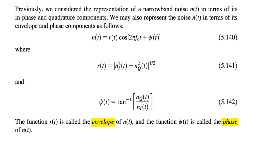
envelope and phase components
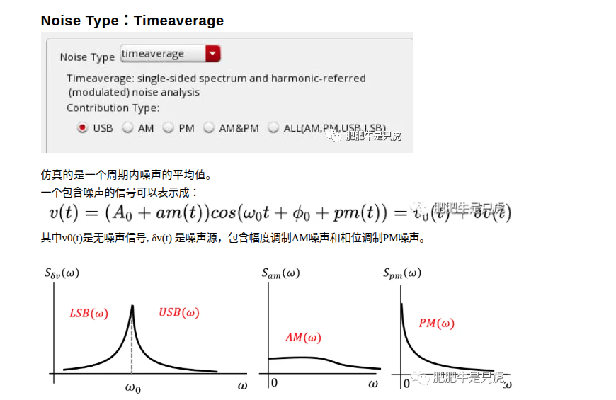
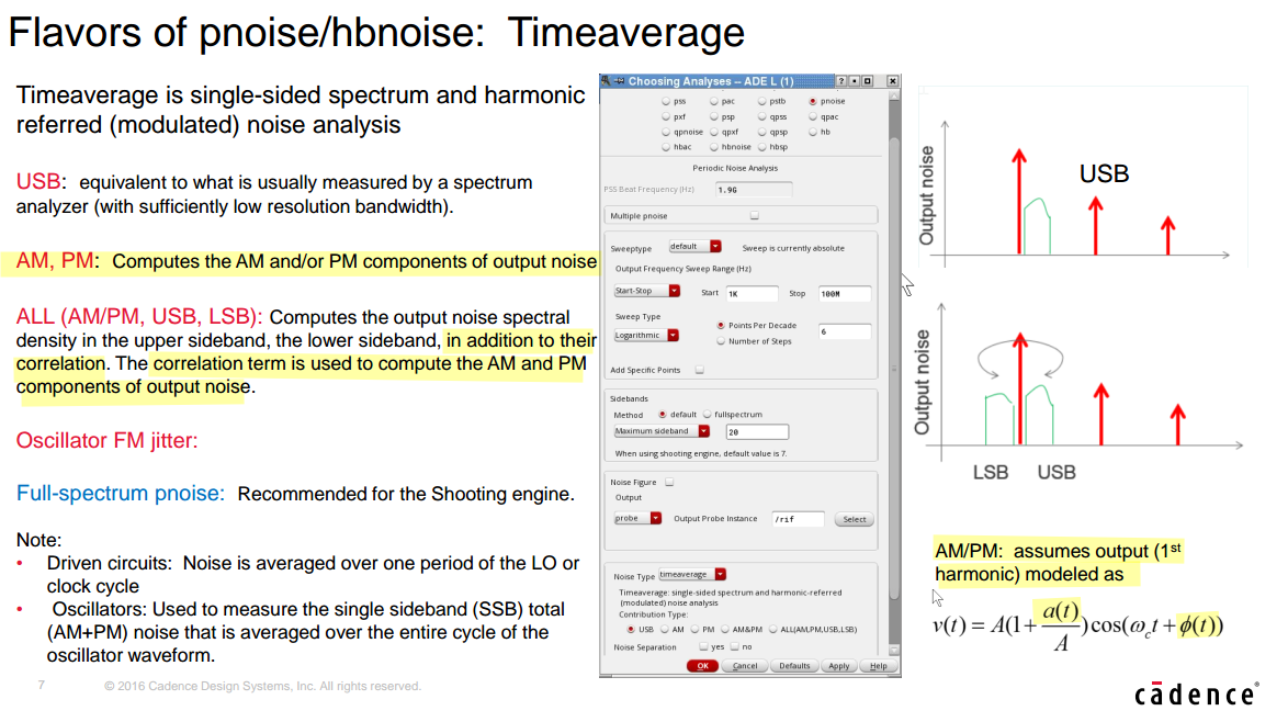
timeaverage Pnoise simulation result
Ken Kundert. Re: Question about phase noise simulation result [https://designers-guide.org/forum/YaBB.pl?num=1309258199/15#15]
Spectre Circuit Simulator RF Analysis Theory — Measuring AM, PM and FM Conversion

| noise profile | sidebands | contribution |
|---|---|---|
| stationary | uncorrelated | \(S_{AM} = S_{PM}\) |
| cyclostationary | correlated | \(S_{AM} \gt S_{PM}\) or \(S_{AM} \lt S_{PM}\) |
sine wave + white noise
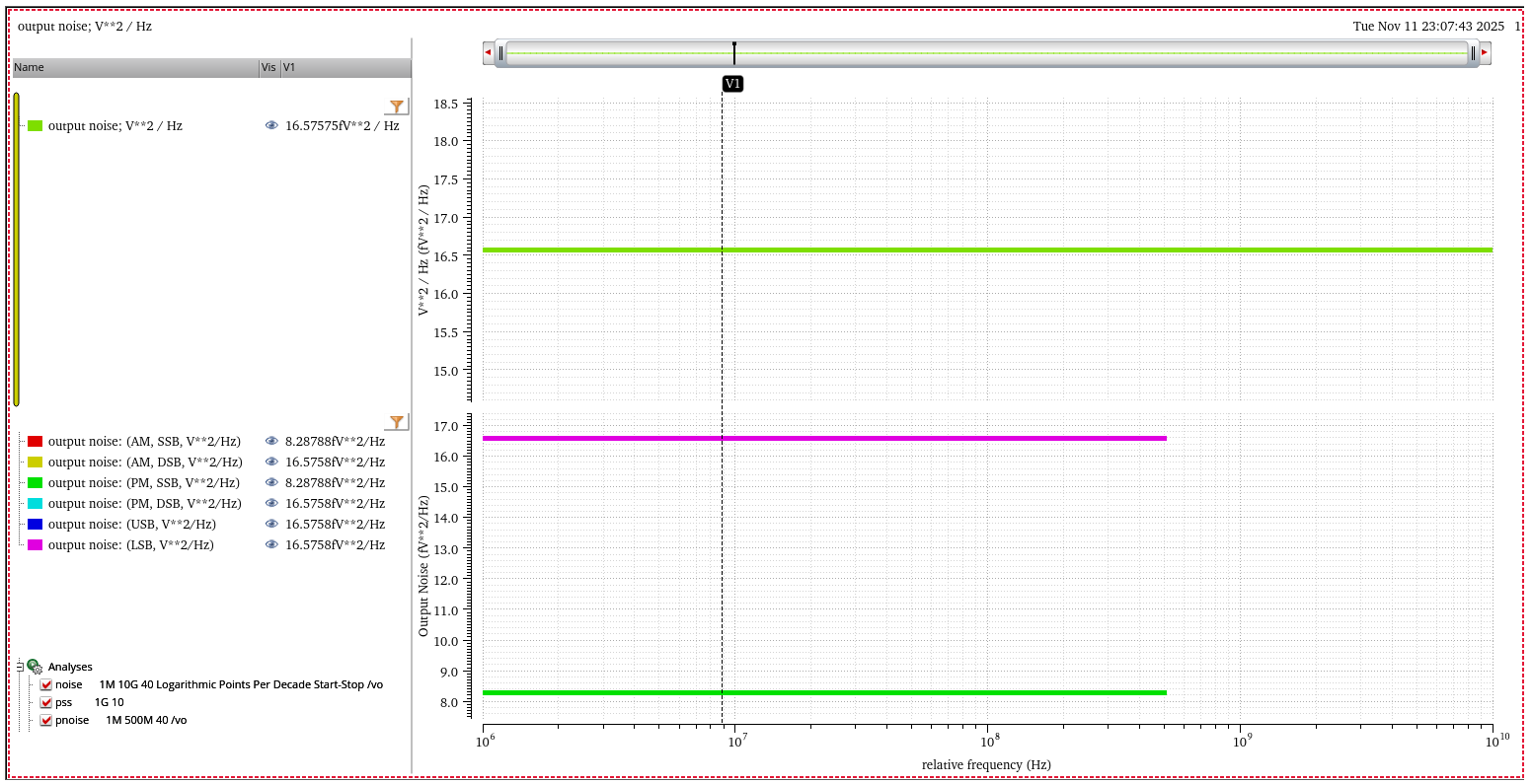
equal amounts of AM and PM noise in both USB and LSB
sine wave + AM
肥肥牛是只虎. PSS+Pnoise仿真:基本设置 [https://mp.weixin.qq.com/s/etyQ2UkfisPkvbc44XFw4w]
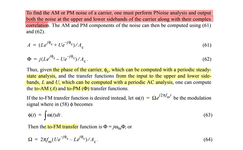
AM & PM Noise Separation
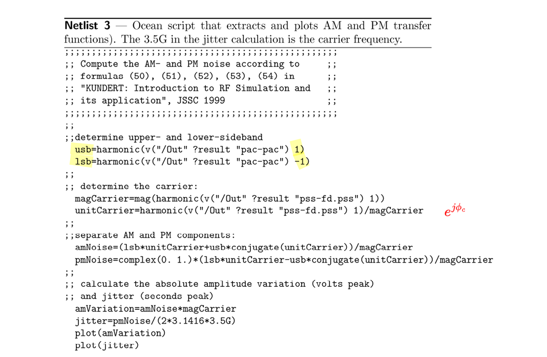
Ken Kundert. Introduction to RF Simulation and its Application [https://designers-guide.org/analysis/rf-sim.pdf]

For AM & pacphase=90deg, complex exponentials with frequency \(\omega_m\) \[ \alpha_+(t) = je^{j\omega_m t} = e^{j(\omega_mt+\pi/2)} \] where \(A_+=j\)
Then, the complex exponentials with frequency \(-\omega_m\) shall be \[ \alpha_-(t) = [\alpha_+(t)]^* = -je^{-j\omega_m t} = e^{-j(\omega_mt+\pi/2)} \] where \(A_-=A_+^* =-j\)
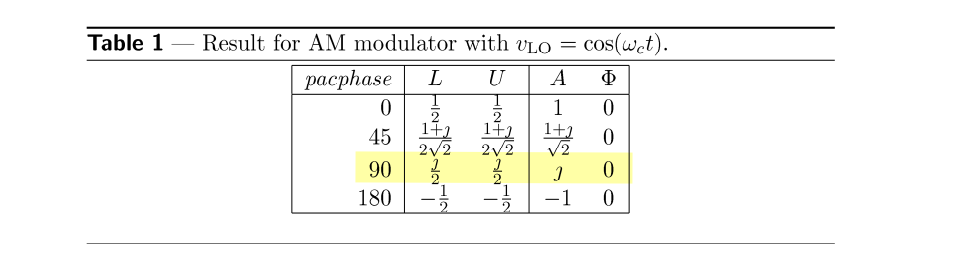
[https://designers-guide.org/analysis/am-pm-conv.pdf]
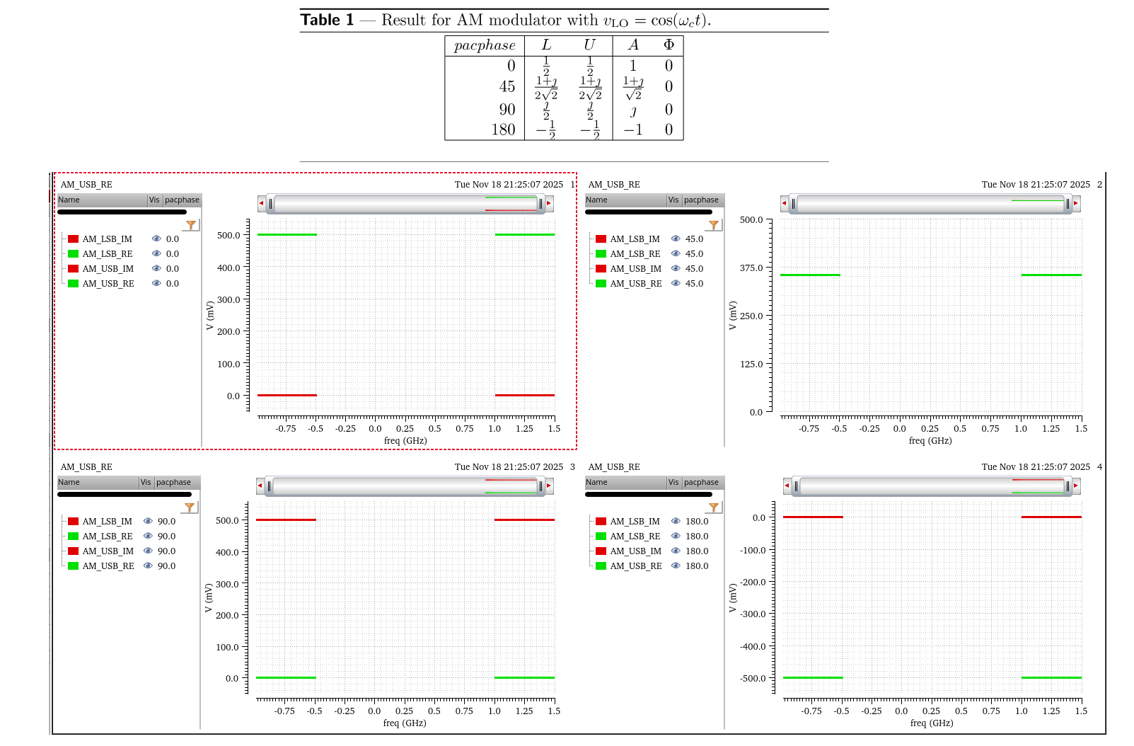
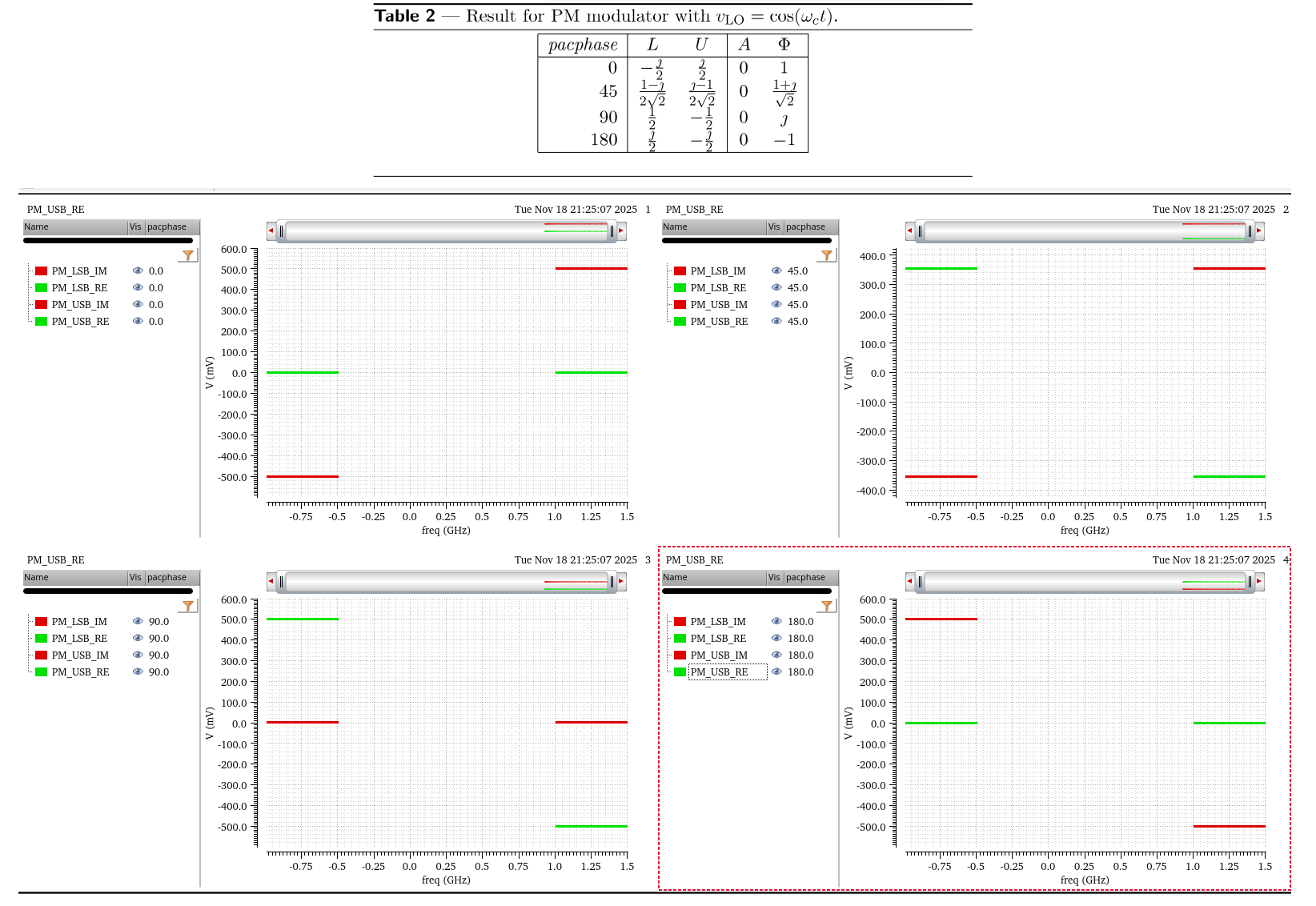
\(\phi_c=0\) in above simulation
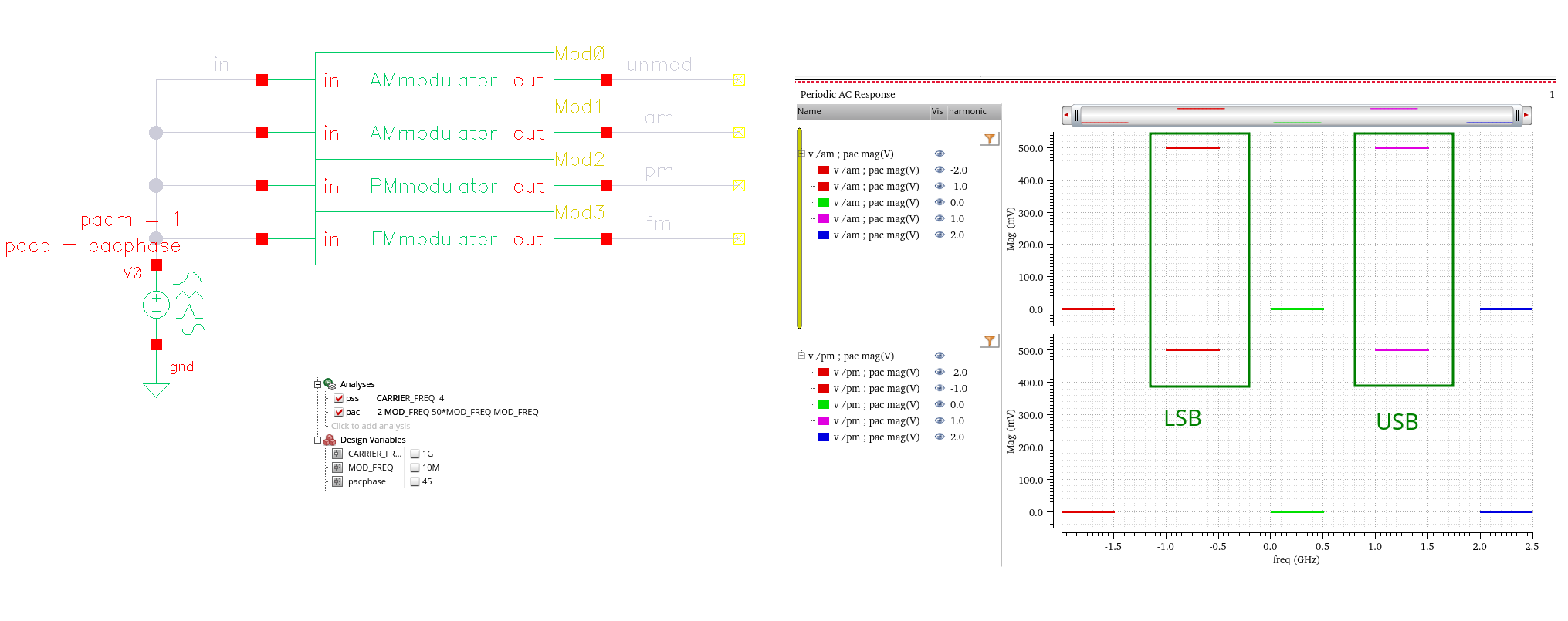
Single Sideband Modulation (SSB)

Asymmetrical Linear System
Golara, S. (2015). Identifying Mechanisms of AM-PM Distortion in Large Signal Amplifiers. UCLA [https://escholarship.org/uc/item/4jp786z8]
Bob Nelson. Phase Noise 101: Basics, Applications and Measurements [[https://www.qsl.net/ab4oj/test/docs/20180720_KEE7_PhaseNoise.pdf])https://www.qsl.net/ab4oj/test/docs/20180720_KEE7_PhaseNoise.pdf]
AN-PN Conversion
G. Giust, Influence of Noise Processes on Jitter and Phase Noise Measurements [https://www.signalintegrityjournal.com/articles/800-influence-of-noise-processes-on-jitter-and-phase-noise-measurements]
—. "Methodologies for PCIe5 Refclk Jitter Analysis,", PCI-SIG Electrical Workgroup Meeting (Jan. 19, 2018)
—. How to Identify the Source of Phase Jitter through Phase Noise Plots [https://www.sitime.com/company/newsroom/blog/how-identify-source-phase-jitter-through-phase-noise-plots]
AN10072 Determine the Dominant Source of Phase Noise, by Inspection [https://www.sitime.com/support/resource-library/application-notes/an10072-determine-dominant-source-phase-noise-inspection]
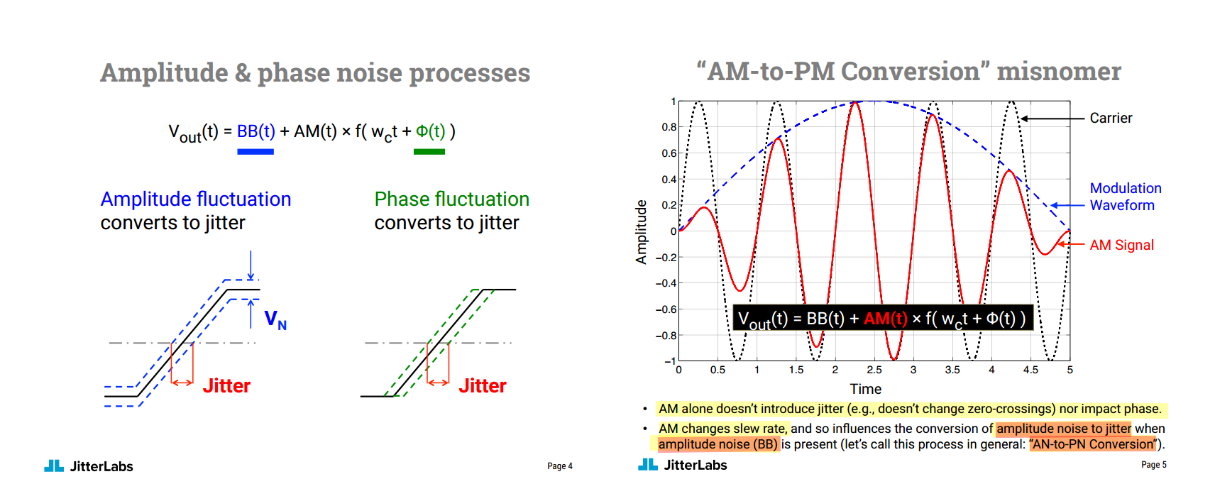
AM alone doesn't introduce jitter (e.g., doesn't change zero-crossings) nor impact phase
AM changes slew rate, and so influences the conversion of amplitude noise to jitter when amplitude noise (BB) is present
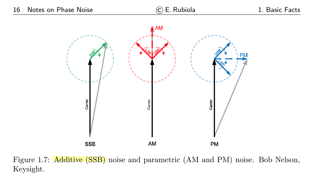
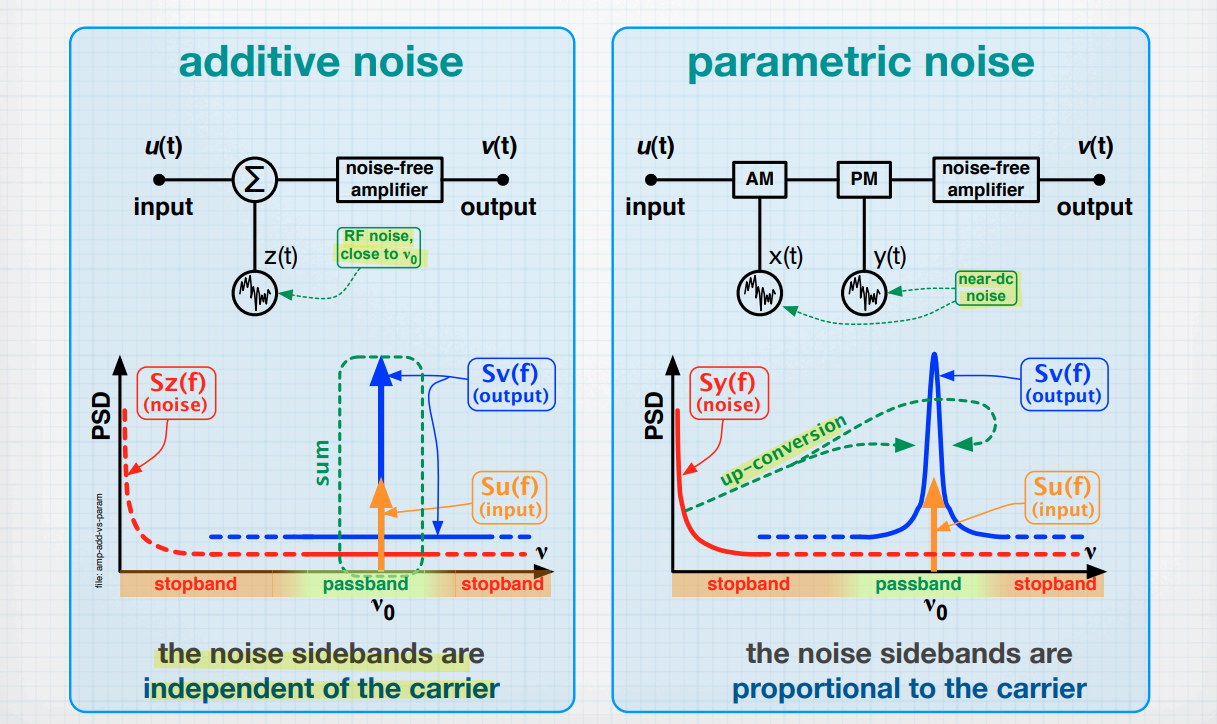
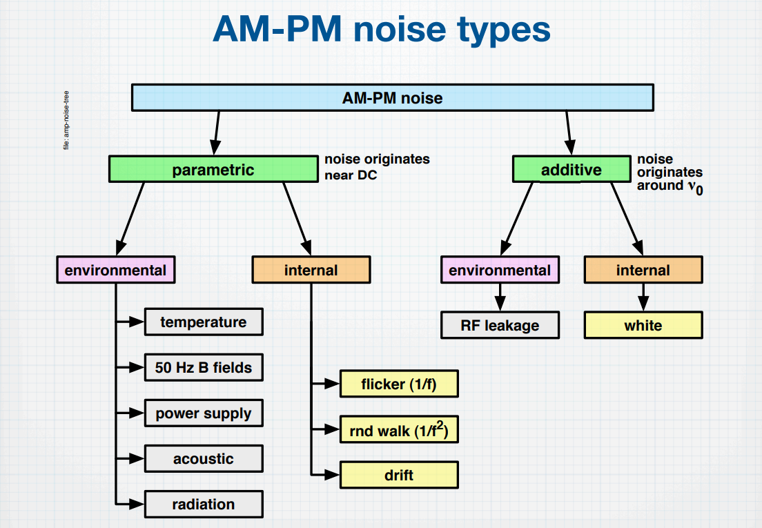
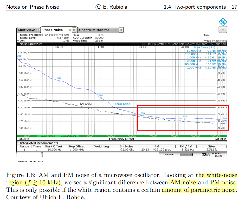
additive & parametric noise
Enrico Rubiola. The Measurement of AM-PM Noise, and the Origin of Noise in Oscillators [https://rubiola.org/pdf-slides/2010T-ANL-Noise-and-oscillators.pdf]
—, February 7, 2025. Phase Noise - Art, Science and Experimental Methods [https://rubiola.org/pdf-lectures/Scient-Instrum-Files/!-Phase-noise.pdf]
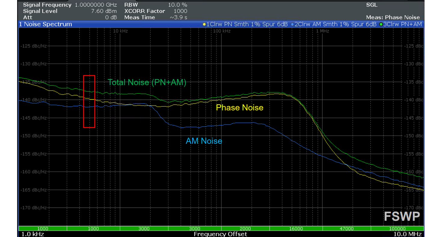
Phase Noise Measurement
Phase Noise Measurement Solutions [https://www.keysight.com/vn/en/assets/7018-02528/technical-overviews/5990-5729.pdf]
Greg Bonaguide. Advances in Phase Noise Measurement Techniques [https://ieee.li/pdf/viewgraphs/advances_in_phase_noise_measurement_techniques.pdf]
The three most widely adopted techniques are direct spectrum, phase detector, and two-channel cross-correlation.
While the direct spectrum technique measures phase noise with the existence of the carrier signal, the other two remove the carrier (demodulation) before phase noise is measured.
Though direct spectrum technique method may not be useful for measuring very close-in phase noise to a drifting carrier, it is convenient for qualitative quick evaluation on sources with relatively high noise
1 | import numpy as np |

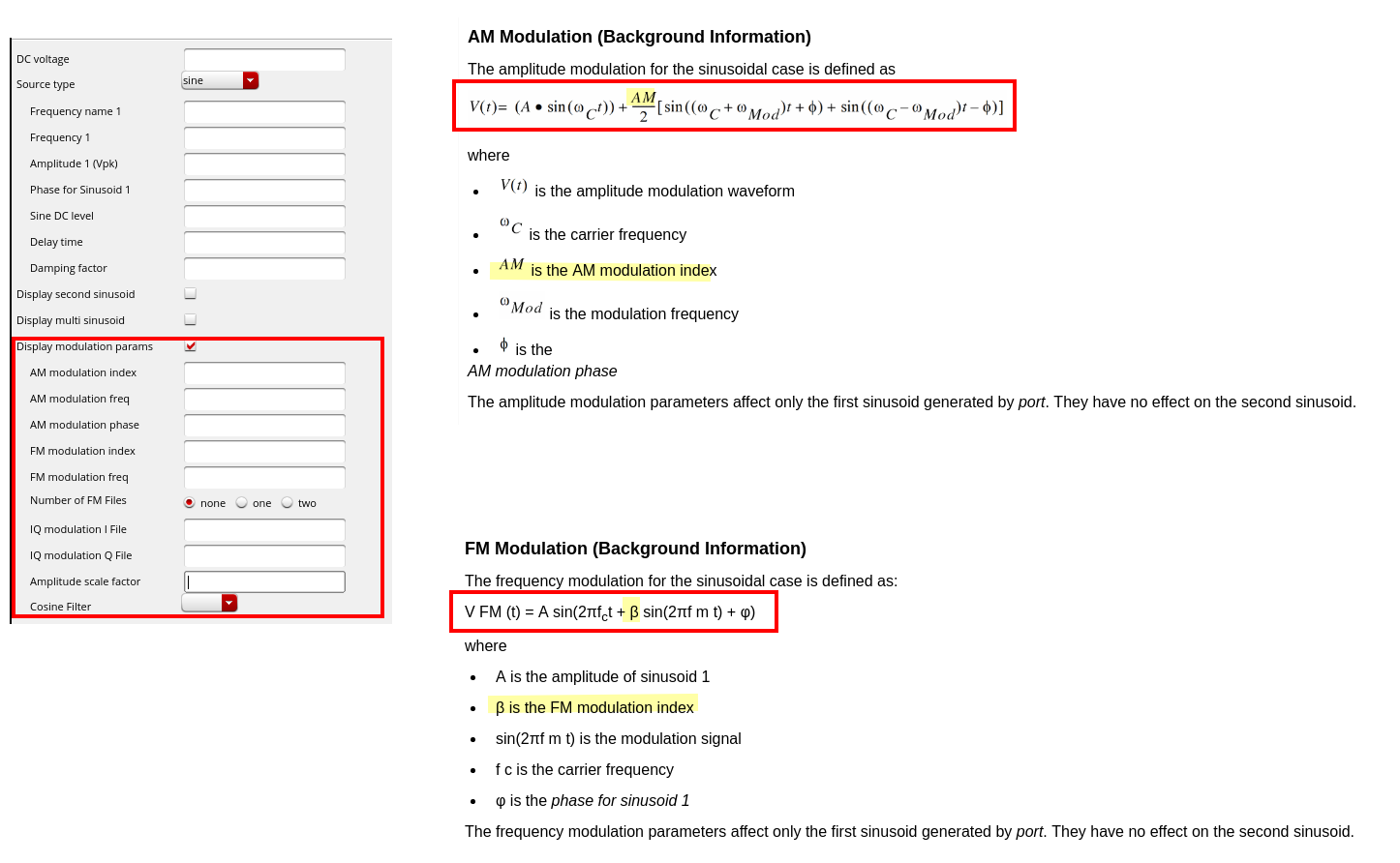
Modulation index in Virtuoso
reference
Ken Kundert, Measuring AM, PM & FM Conversion with SpectreRF [https://designers-guide.org/analysis/am-pm-conv.pdf]
Dan Boschen. Creating uneven sidebands with AM + PM modulation? [https://dsp.stackexchange.com/a/61670/59253]
—. Creating uneven sidebands with AM + PM modulation? [https://dsp.stackexchange.com/a/61670/59253]
—. Qualitative Explanation of Fourier Transform [https://dsp.stackexchange.com/a/78911/59253]
Timing 201 #1: The Case of the Phase Noise That Wasn't - Part 1 [https://community.silabs.com/s/share/a5U1M000000knpiUAA/timing-201-1-the-case-of-the-phase-noise-that-wasnt-part-1?]
Noise in mixers, oscillators, samplers, and logic: an introduction to cyclostationary noise [https://designers-guide.org/theory/cyclo-preso.pdf], [https://designers-guide.org/theory/cyclo-paper.pdf]
Haykin, Simon S., and Michael Moher. Communication Systems. 5th ed. John Wiley & Sons, 2009.