Adaptive Filtering & Synchronization
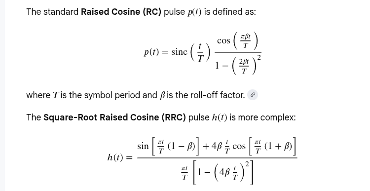
Raised Cosine
Equations for the Raised Cosine and Square-Root Raised Cosine Shapes [https://engineering.purdue.edu/~ee538/SquareRootRaisedCosine.pdf]
Pulse Shaping Filter [https://wirelesspi.com/pulse-shaping-filter/]
| Feature | Raised Cosine (RC) | Root Raised Cosine (RRC) |
|---|---|---|
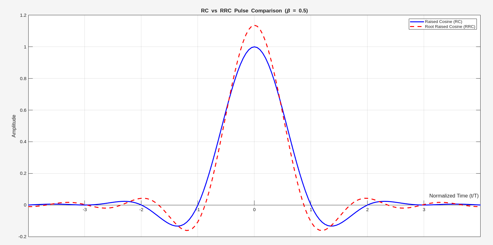
| ISI Property | Satisfies Nyquist ISI criterion (zero crossings at \(t = \pm nT\)) | Does not satisfy ISI criterion on its own |
| Zero Crossings | Crosses zero at every integer multiple of \(T\) | Zero crossings are not periodic at \(T\) |
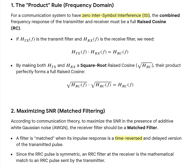
| Usage | Resulting pulse after the whole system | Used at both transmitter and receiver (matched filter) |
| Decay Rate | Faster decay in the time domain | Slower decay compared to RC |
| Peak Value | Normalized to 1 at \(t=0\) | Often normalized so that \(\int |h(t)|^2 dt = 1\) |
Why Root Raised Cosine (RRC) Used at both transmitter and receiver ?
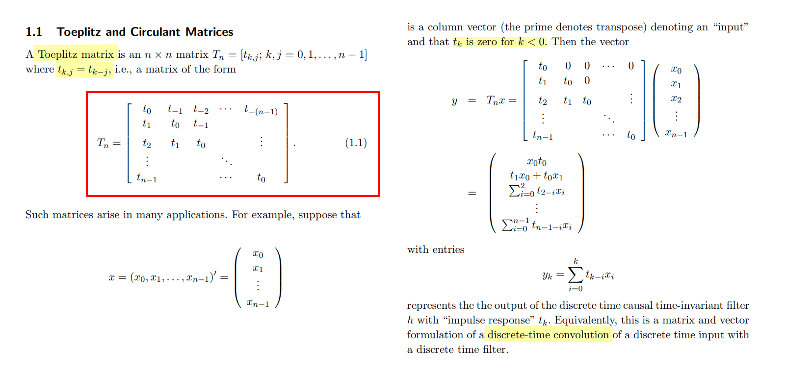
Toeplitz matrix
Robert M. Gray, Toeplitz and Circulant Matrices: A review [https://ee.stanford.edu/~gray/toeplitz.pdf]
toeplitzToeplitz matrix, [https://www.mathworks.com/help/matlab/ref/toeplitz.html]
ZFS
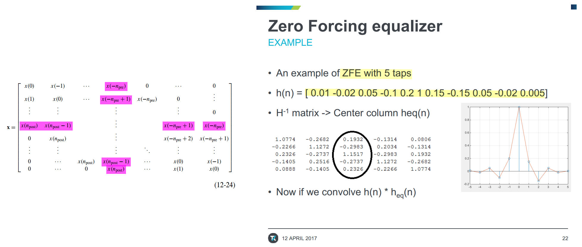
1 | h = [0.01 -0.02 0.05 -0.1 0.2 1 0.15 -0.15 0.05 -0.02 0.005]; |
MMSE
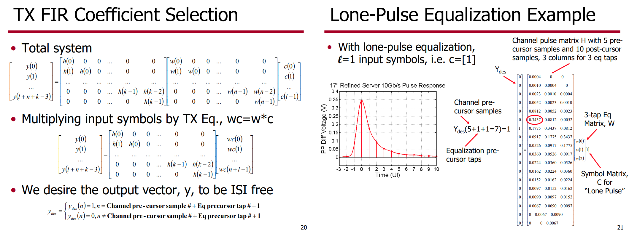
1 | h=[0.004, 0.0010, 0.0023, 0.0052, 0.0812, 0.3437, 0.1775, 0.0917, 0.0526,... |
transpose(toeplitz(c,r)) is same with
toeplitz(r,c)
1 | isequal(transpose(toeplitz(c, r)), toeplitz(r, c)) % logical 1 |
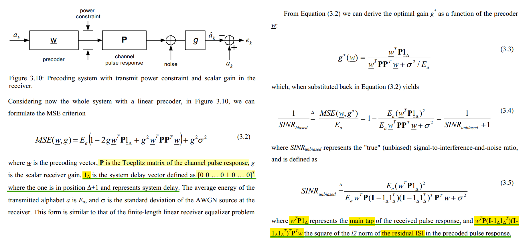
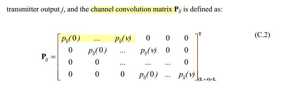
V. Stojanovic, "Channel-Limited High-Speed Links: Modeling, Analysis and Design," PhD. Thesis, Stanford University, Sep. 2004. [pdf]
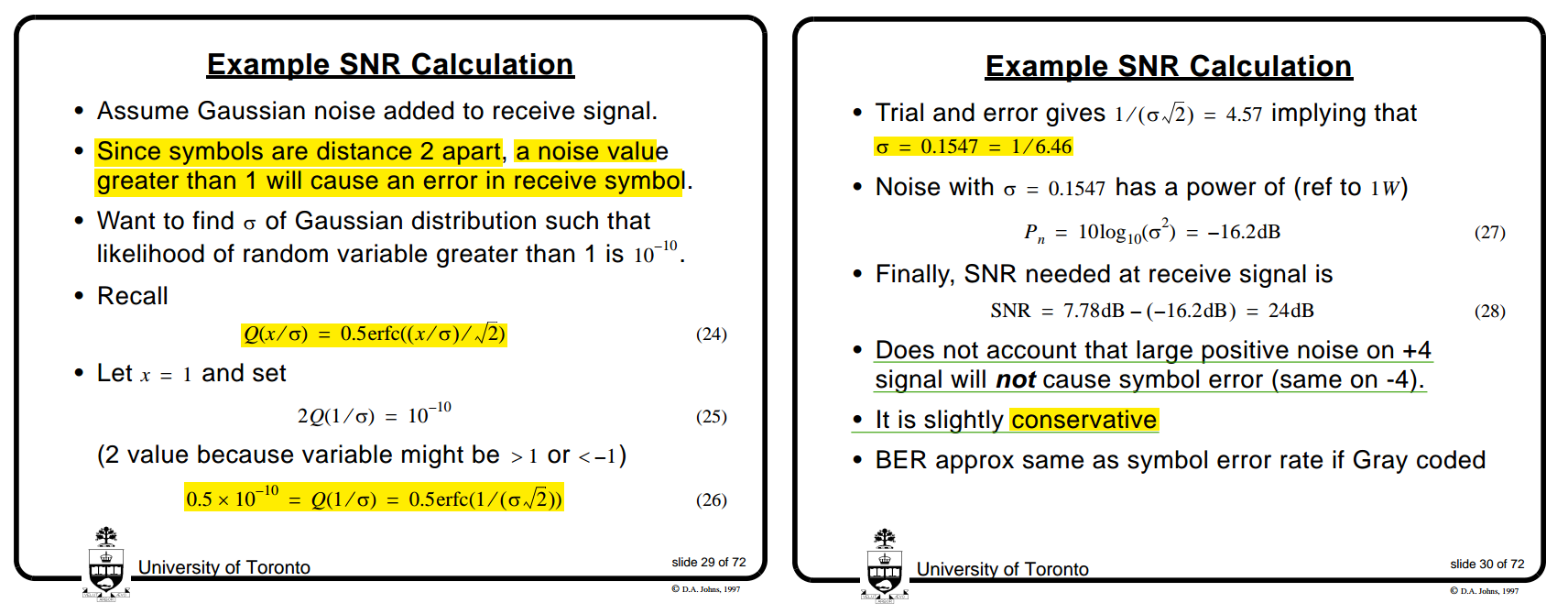
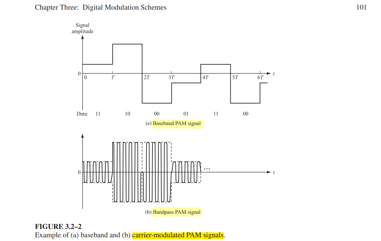
Bandpass Modulation
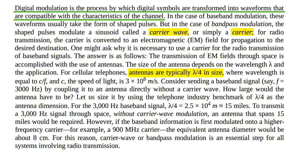
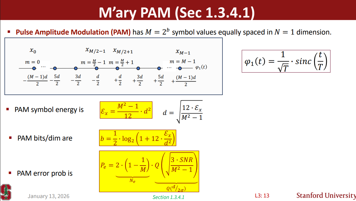
Pulse Amplitude Modulation (PAM)
David A. Johns, ECE1392H - Integrated Circuits for Digital Communications - Fall 2001 [System Overview]
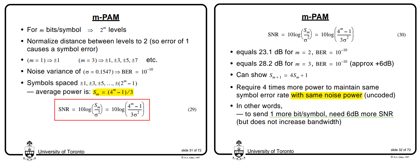
\(S_m\) Google AI mode [https://share.google/aimode/BzYr2logpVTVs83LQ]
1 | snr_mpam = @(m,simga) 10*log10((4^m-1)/simga^2/3); |
Lecture 3, Tuesday January 13th 2026 - Modulation Types (PAM/QAM) [https://cioffi-group.stanford.edu/ee379a/Lectures/L3.pdf]
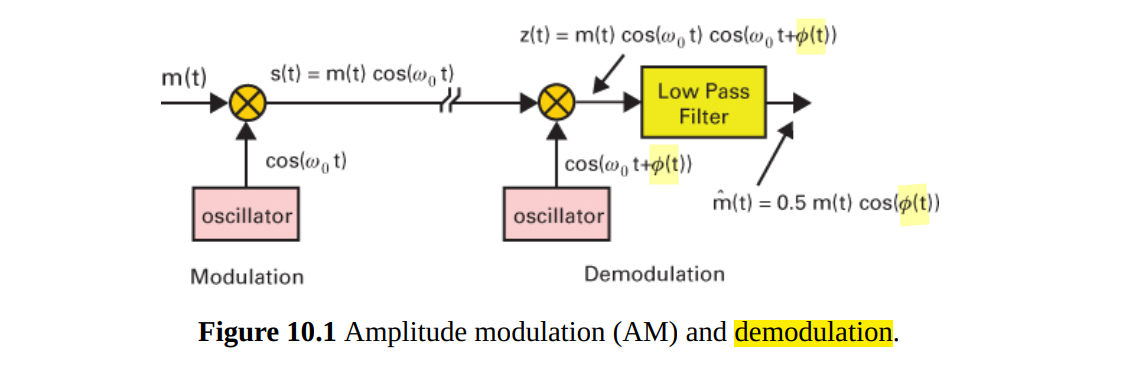
Carrier & Symbol Synchronization
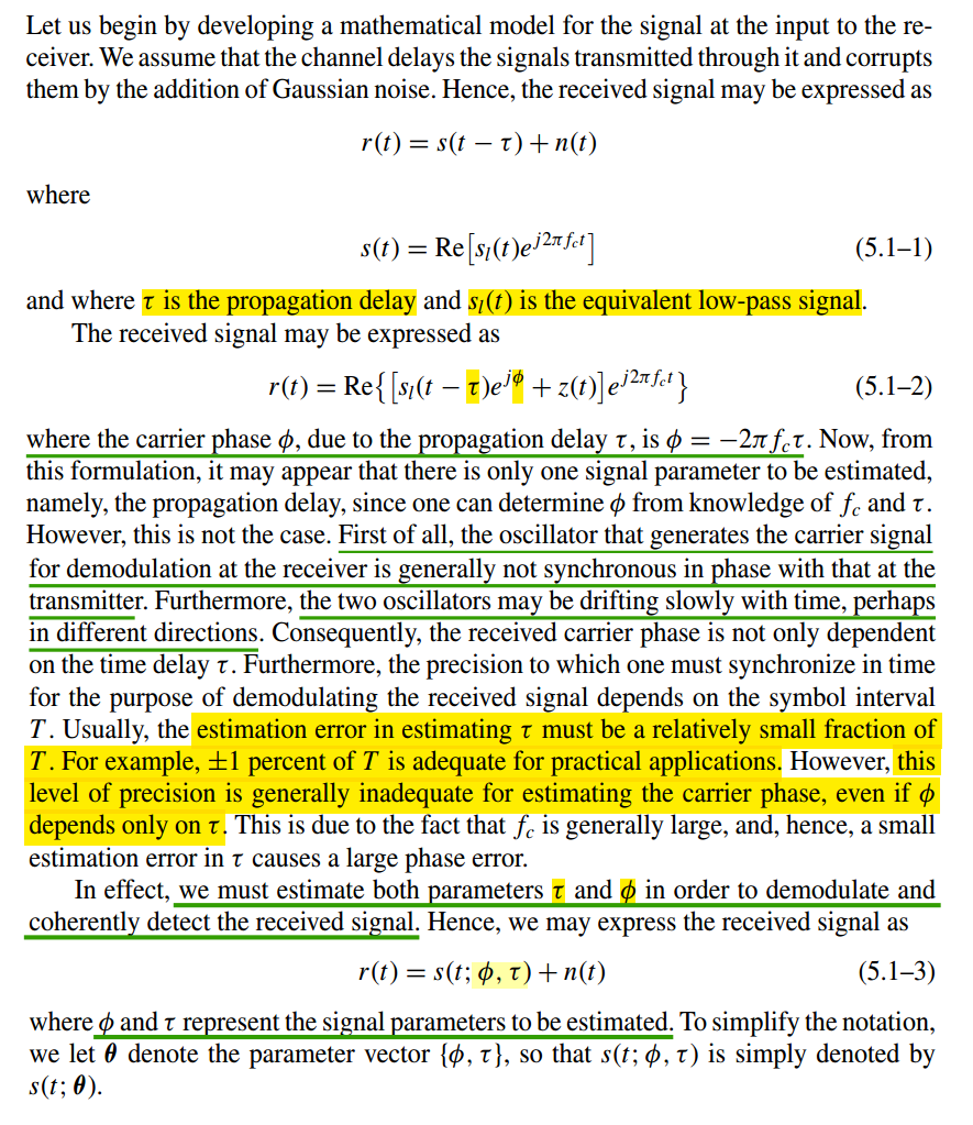
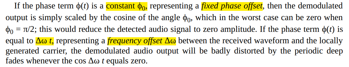
\(\Delta\tau \lt \pm \frac{1}{100} T\) don't ensure \(\Delta \phi \ll 2\pi\) due to \(T \gg \frac{1}{f_c}\)
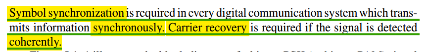
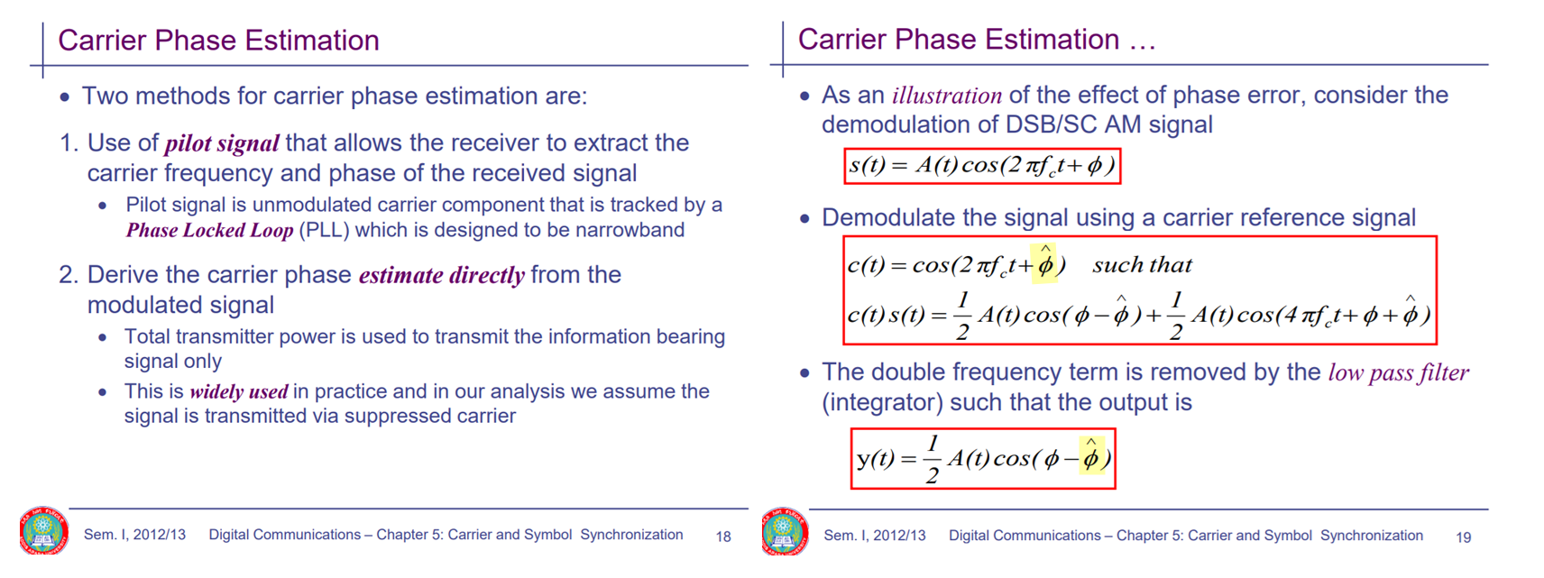
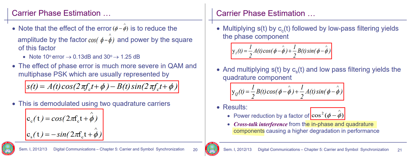
Carrier Synchronization
[https://ndl.ethernet.edu.et/bitstream/123456789/87843/14/LECT_13%2614.Synchronization.pdf]
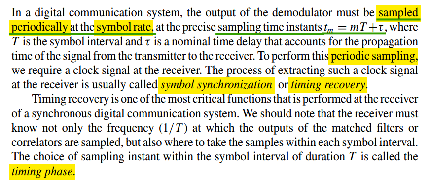
Symbol Synchronization
[https://www.ieee802.org/3/dm/public/1125/cordaro_3dm_01_1125.pdf]
Mathuranathan, Symbol Timing Recovery for QPSK (digital modulations) [https://www.gaussianwaves.com/2013/11/symbol-timing-recovery-for-qpsk-digital-modulations/]
Qasim Chaudhari. Early-Late Bit Synchronizer in Digital Communication [https://wirelesspi.com/early-late-bit-synchronizer-in-digital-communication/]
Igor Freire. Symbol Timing Synchronization: A Tutorial [blog, code]
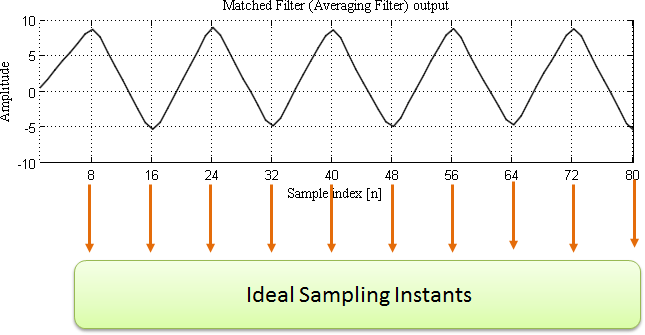
But the problem here is: "How does the receiver know the ideal sampling instants?". The solution is "someone has to supply those ideal sampling instants". A symbol time recovery circuit is used for this purpose.
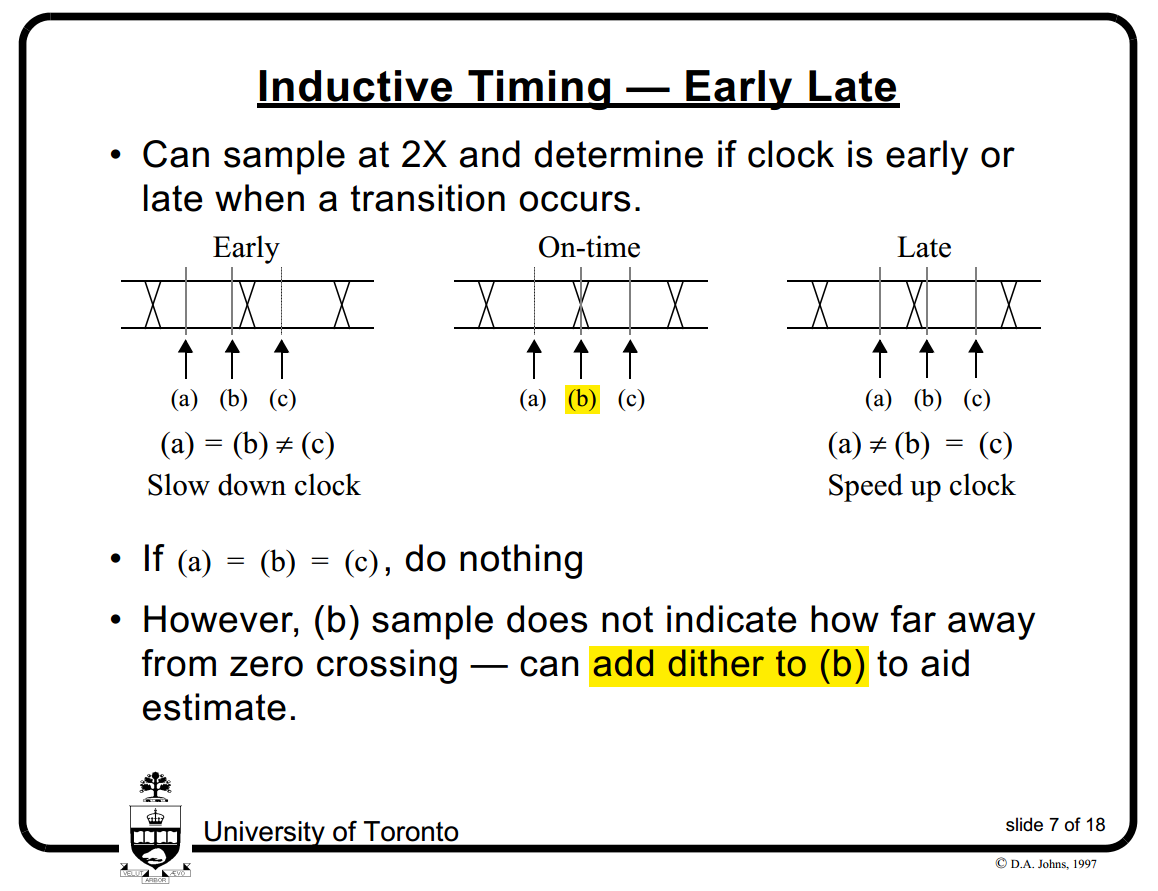
Early/Late Symbol Recovery algorithm
- non-decision-directed timing estimator exploits the symmetry properties of the signal
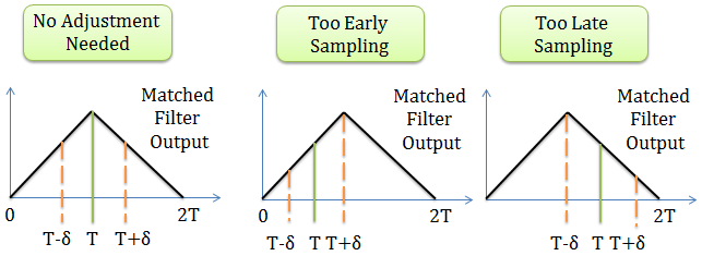
- If the Early Sample = Late Sample : The peak occurs at the on-time sampling instant \(T\). No adjustment in the timing is needed.
- If |Early Sample| > |Late Sample| : Late timing, the sampling time is offset so that the next symbol is sampled \(T-\delta/2\) seconds after the current sampling time.
- If |Early Sample| < |Late Sample| : Early timing, the sampling time is offset so that the next symbol is sampled \(T+\delta/2\) seconds after the current sampling time.
David Johns. ECE1392H - Integrated Circuits for Digital Communications - Fall 2001: [Timing Recovery]
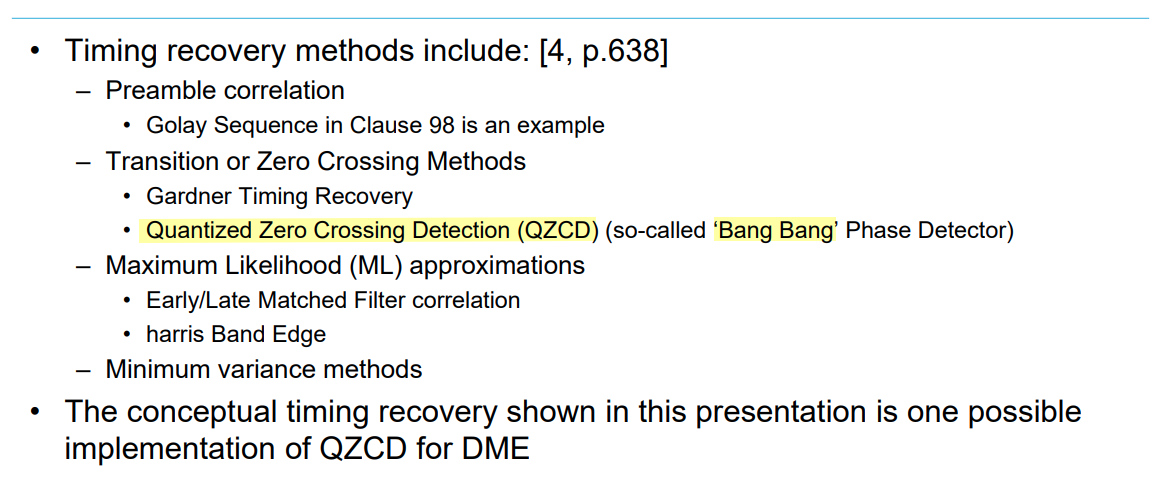
Dither in Quantized Zero Crossing Detection (QZCD) (so-called 'Bang Bang' Phase Detector)
Mueller and Muller Timing Synchronization
K. Mueller and M. Muller, "Timing Recovery in Digital Synchronous Data Receivers," in IEEE Transactions on Communications, vol. 24, no. 5, pp. 516-531, May 1976 [pdf]
Qasim Chaudhari. Mueller and Muller Timing Synchronization Algorithm [https://wirelesspi.com/mueller-and-muller-timing-synchronization-algorithm/]
Eduardo Fuentetaja. "Analysis of the M&M Clock Recovery Algorithm" [https://edfuentetaja.github.io/sdr/m_m_analysis/]
C.-P. Tzeng, D. Hodges and D. Messerschmitt, "Timing Recovery in Digital Subscriber Loops Using Baud-Rate Sampling," in IEEE Journal on Selected Areas in Communications, vol. 4, no. 8, pp. 1302-1311, November 1986 [pdf]
H. Meyr, M. Moeneclaey, and S. A. Fechtel. "Digital Communication Receivers: Synchronization, Channel Estimation, and Signal Processing." Wiley [pdf]
T. Musah and A. Namachivayam, "Robust Timing Error Detection for Multilevel Baud-Rate CDR," in IEEE Transactions on Circuits and Systems I: Regular Papers, vol. 69, no. 10, pp. 3927-3939, Oct. 2022 [https://sci-hub.jp/10.1109/TCSI.2022.3191740]
Fulvio Spagna, CICC2018 Clock and Data Recovery Systems [pdf]
TODO 📅
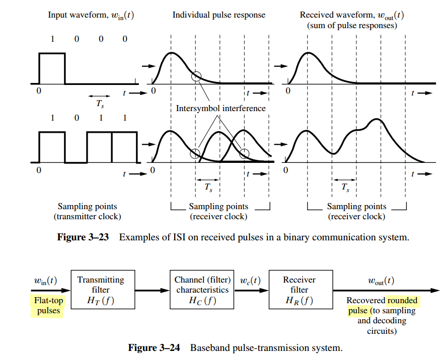
Intersymbol Interference (ISI)
L.W. Couch, Digital and Analog Communication Systems, 8th Edition, Pearson, 2013. [pdf]
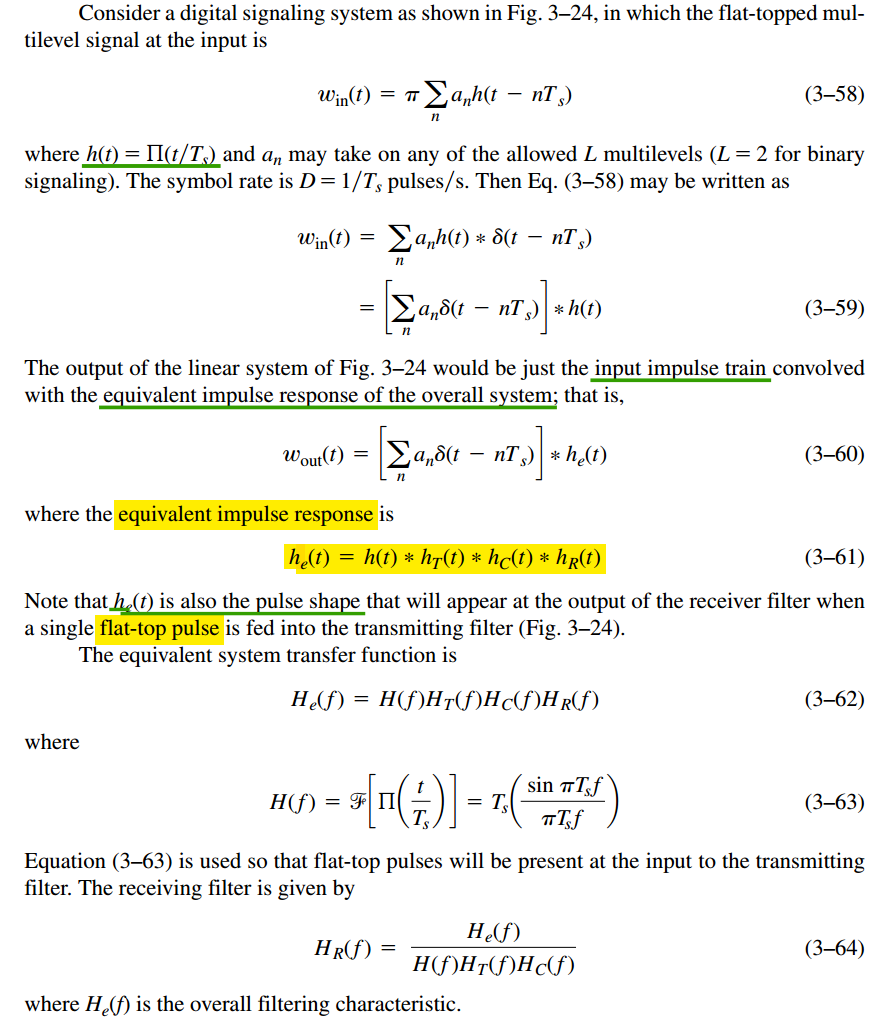
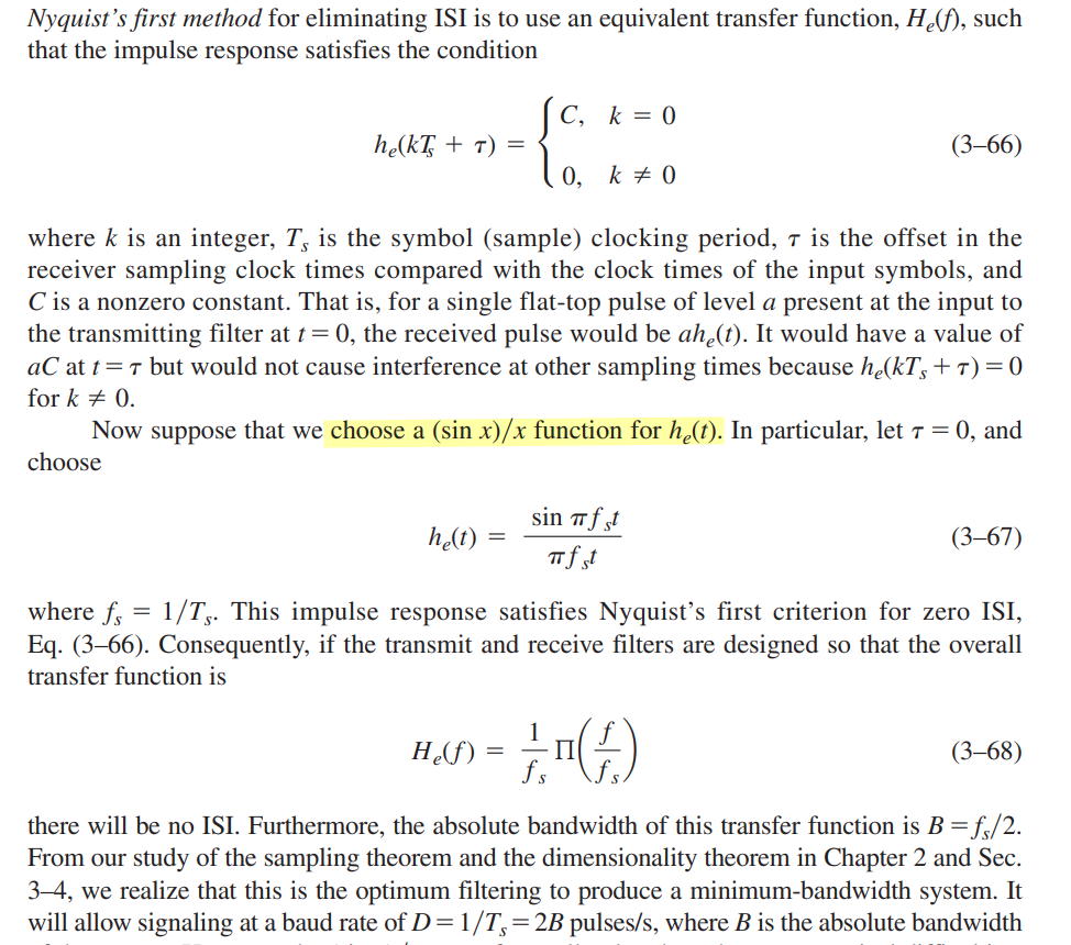
Nyquist discovered three different methods for pulse shaping that could be used to eliminate ISI
Nyquist's First Method (Zero ISI): physically unrealizable (i.e., the impulse response would be noncausal and of infinite duration), inaccurate sync will cause ISI
Nyquist's second method: allows some ISI to be introduced in a controlled way
Nyquist's third method: area under the \(h_e(t)\) pulse within the desired symbol interval, \(T_s\), is not zero, but the areas under \(h_e(t)\) in adjacent symbol intervals are zero
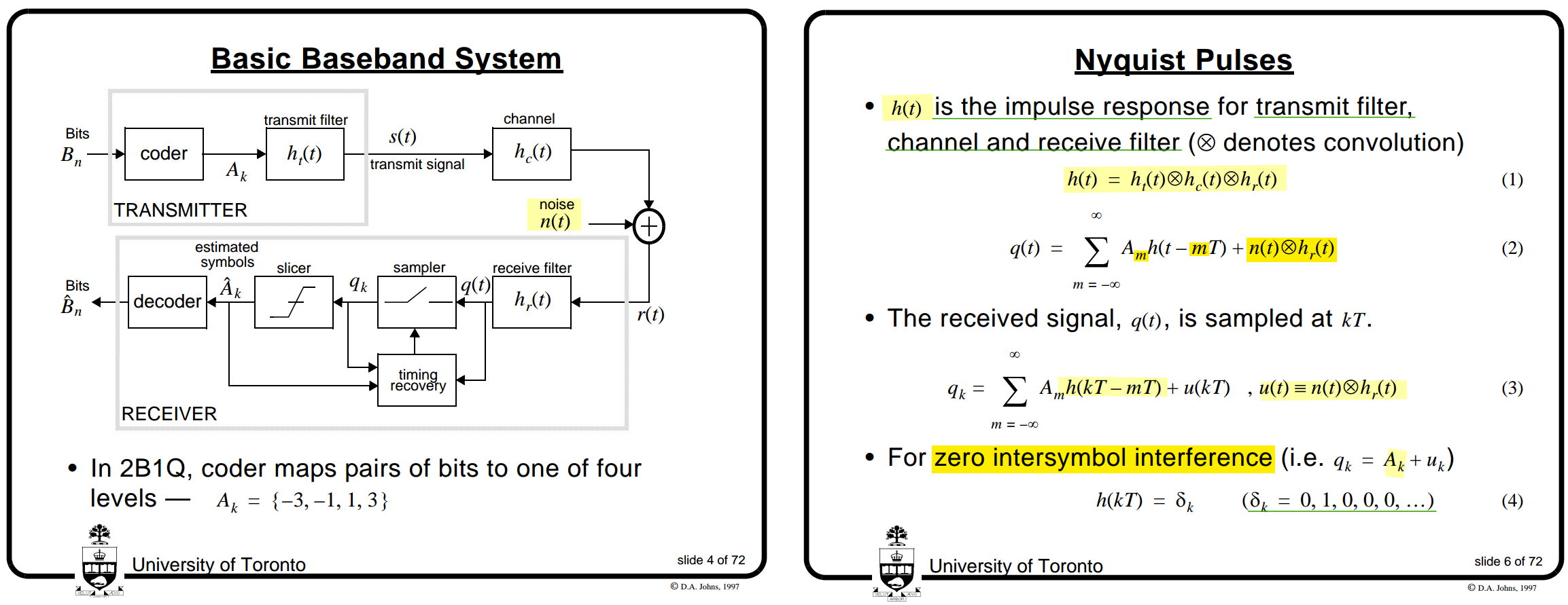
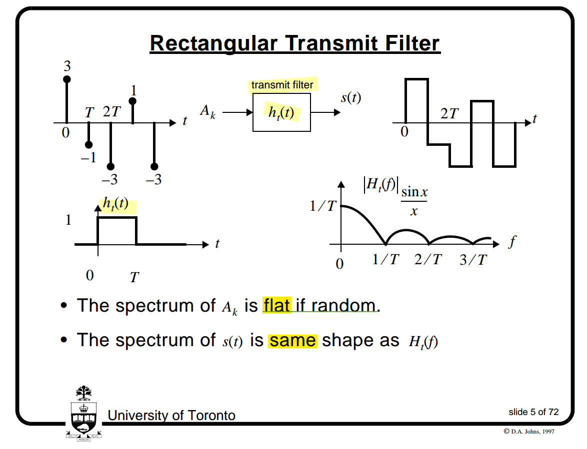
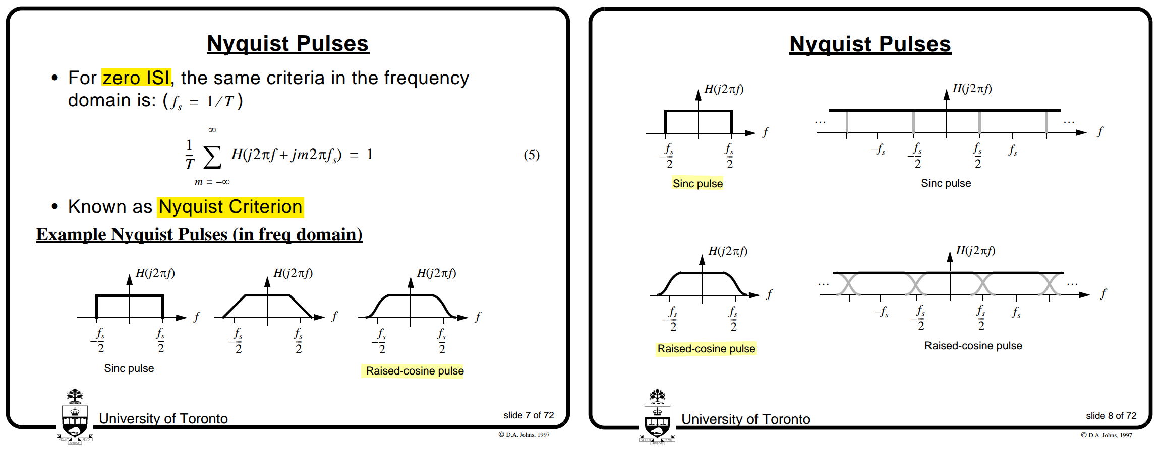
Nyquist Criterion & Pulses
David A. Johns, ECE1392H - Integrated Circuits for Digital Communications - Fall 2001 [System Overview]
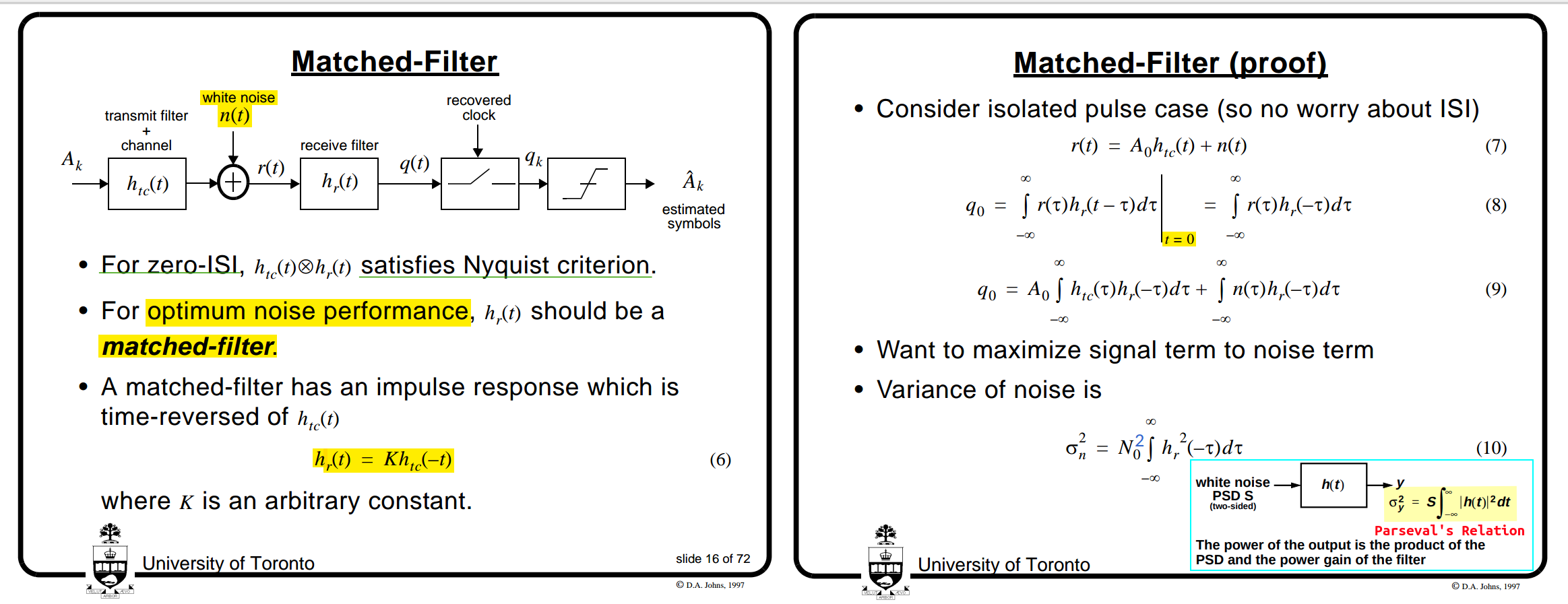
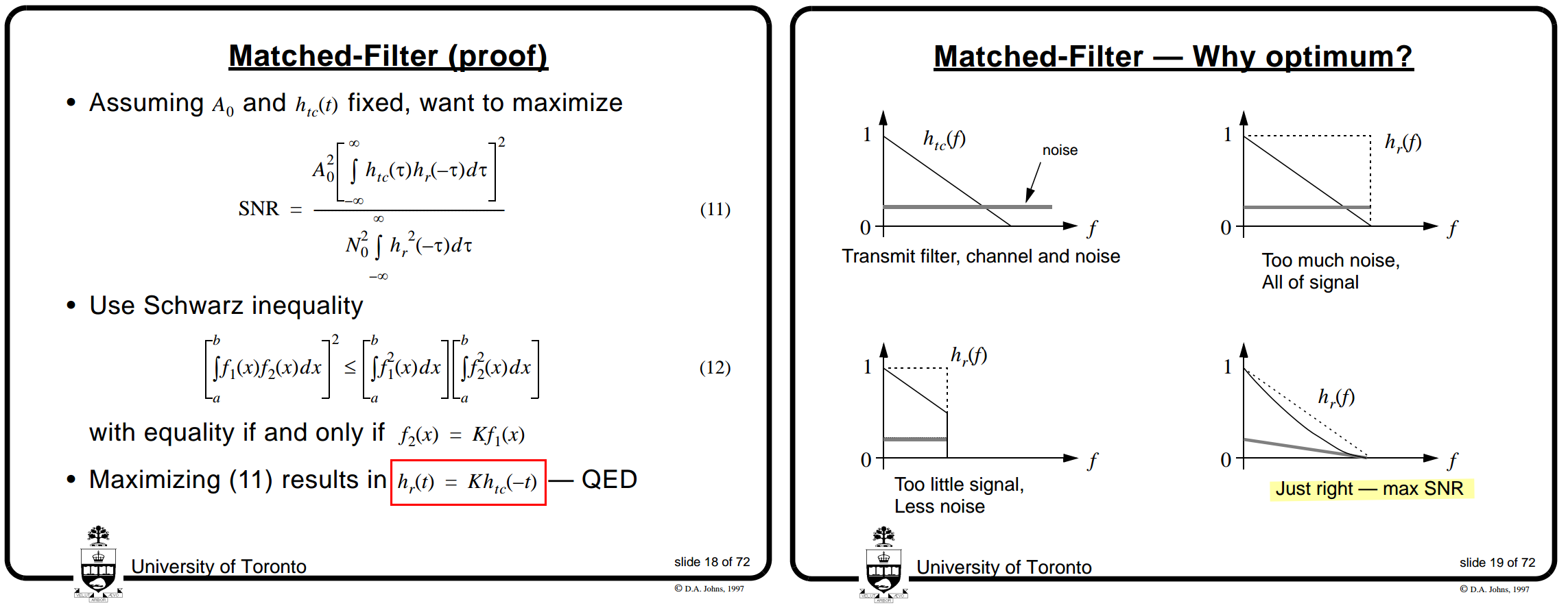
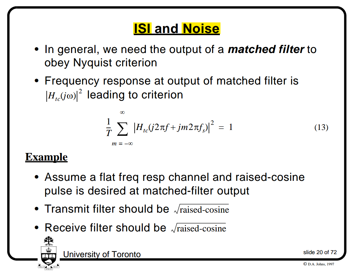
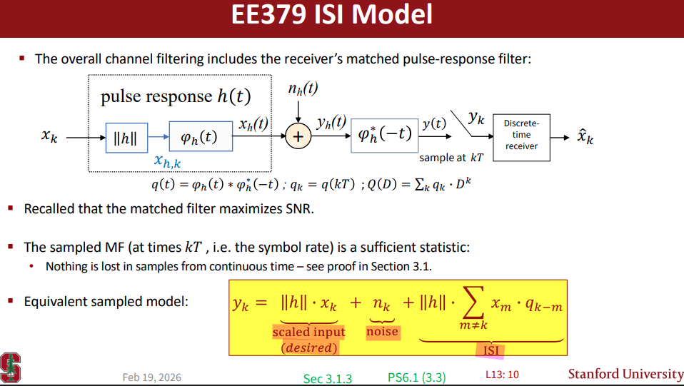
Matched-Filter (MF)
David A. Johns, ECE1392H - Integrated Circuits for Digital Communications - Fall 2001 [System Overview]
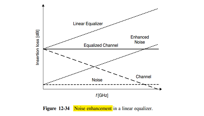
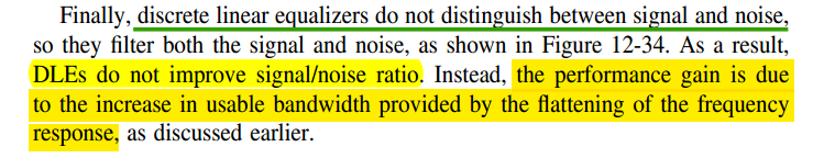
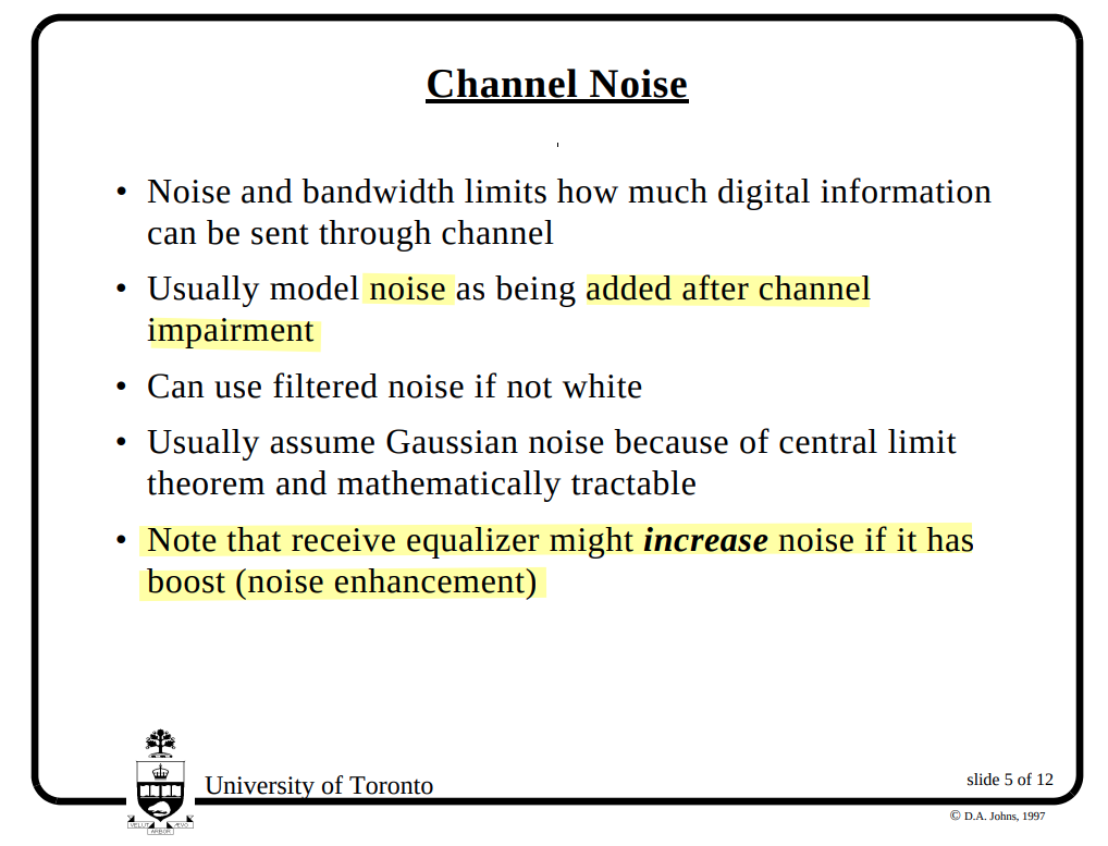
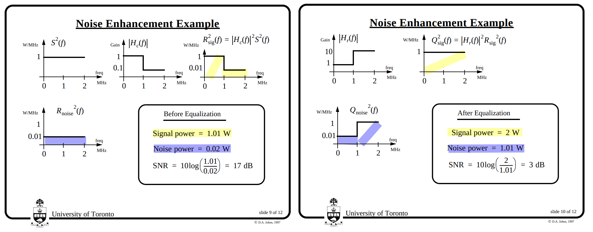
Noise Enhancement in Linear Equalizers
John M. Cioffi, Lecture 13, Thursday February 19th 2026 - Intersymbol Interference, MMSE, and SNR [https://cioffi-group.stanford.edu/ee379a/Lectures/L13.pdf]
—, Lecture 14, Tuesday February 24th 2026 - Linear Equalizers [https://cioffi-group.stanford.edu/ee379a/Lectures/L14.pdf]
Shannon–Hartley theorem
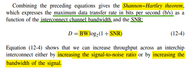
David A. Johns, ECE1392H - Integrated Circuits for Digital Communications - Fall 2001 [Introduction]
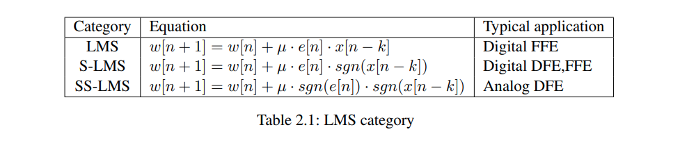
LMS & its Quantized-Error Algorithms
Bruno Lima, Adaptive filtering in Python Implementations based on Adaptive Filtering: Algorithms and Practical Implementation (Paulo S. R. Diniz). [https://github.com/BruninLima/PydaptiveFiltering]
\[\begin{align} x_k &= [x[k], x[k-1], \ldots, x[k-M]]^T \in \mathbb{C}^{M+1}\\ y[k] &= w^H[k] x_k, \qquad e[k] = d[k] - y[k], \end{align}\]
LMS algorithm
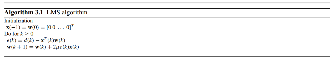 \[
w[k+1] = w[k] + \mu\, e^*[k] \, x_k.
\]
\[
w[k+1] = w[k] + \mu\, e^*[k] \, x_k.
\]
1 | if w_init is not None: |
1 | x: np.ndarray = np.asarray(input_signal, dtype=complex).ravel() |
Sign-Data Algorithm \[ w[k+1] = w[k] + 2\mu\, e^*[k] \, \operatorname{sign}(x_k) \]
1 | for k in range(n_samples): |
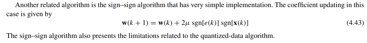
sign–sign algorithm
reference
Proakis, John G., and Masoud Salehi. Digital Communications. 5th ed. McGraw-Hill, 2008. [pdf]
Sklar, Bernard. Digital communications: fundamentals and applications. Pearson, 2021.
Ling, F. (2017). Synchronization in Digital Communication Systems. Cambridge: Cambridge University Press.
Barry, John R., Edward A. Lee, and David G. Messerschmitt. Digital communication. Springer, 2003.
Qasim Chaudhari, Wireless Communications From the Ground Up – An SDR Perspective
John M. Cioffi, [Chapter 3 - Equalization], [Chapter 6 - Fundamentals of Synchronization]
Sen M. Kuo. Real-Time Digital Signal Processing: Fundamentals, Implementations and Applications, 3rd Edition. John Wiley & Sons 2013
Stankovic, Ljubisa. (2015). Digital Signal Processing with Selected Topics.
Paulo S. R. Diniz, Adaptive Filtering: Algorithms and Practical Implementation, 5th edition [pdf], [matlab], [python]
B. Farhang-Boroujeny (2013), Adaptive Filters: Theory and Applications (2nd ed.). John Wiley & Sons, Inc.
Simon O. Haykin (2014), "Adaptive Filter Theory" Prentice-Hall, Inc. 5rd edition
A. Chan Carusone and D. A. Johns, "Analog Filter Adaptation Using a Dithered Linear Search Algorithm," IEEE Int. Symp. Circuits and Syst., May 2002. [PDF], [Slides]
—, Ph. D. Thesis, "Digital Algorithms for Analog Adaptive Filters", Feb. 2002. [http://www.eecg.utoronto.ca/~tcc/thesis.pdf]
—, "Analog Adaptive Filters," tutorial at the IEEE Int. Symp. Circuits and Syst., Bangkok, Thailand, May 2003. [http://www.eecg.utoronto.ca/~tcc/iscas03_tutorial.pdf]
—, 2022 Optimization Tools for Future Wireline Transceivers [https://www.ieeetoronto.ca/wp-content/uploads/2022/12/UofT-Future-of-Wireline-Workshop-2022.pdf]
David Johns, "Integrated Circuits for Digital Communications" [https://www.eecg.toronto.edu/~johns/nobots/courses/ece1392/slides.pdf]
Chris Li, mmse_dfe [https://github.com/ChrisZonghaoLi/mmse_dfe]
ScottXjw, equalizer-code-FFE-DFE-VolterraFFEandDFE [https://github.com/ScottXjw/equalizer-code-FFE-DFE-VolterraFFEandDFE]
Qasim Chaudhari. Maximum Likelihood Estimation of Clock Offset [https://wirelesspi.com/maximum-likelihood-estimation-of-clock-offset/]
—. Channel Estimation in Wireless Communication. [https://wirelesspi.com/channel-estimation-in-wireless-communication/]
—. Phase Locked Loop (PLL) in a Software Defined Radio (SDR) [https://wirelesspi.com/phase-locked-loop-pll-in-a-software-defined-radio-sdr/]
—. Phase Locked Loop (PLL) for Symbol Timing Recovery [https://wirelesspi.com/phase-locked-loop-pll-for-symbol-timing-recovery/]
—. How Decision Feedback Equalizers (DFE) Work [https://wirelesspi.com/how-decision-feedback-equalizers-dfe-work/]
—. Maximum Likelihood Sequence Estimation (MLSE Equalizer) [https://wirelesspi.com/maximum-likelihood-sequence-estimation-mlse-equalizer/]
—. Gardner Timing Error Detector: A Non-Data-Aided Version of Zero-Crossing Timing Error Detectors [https://wirelesspi.com/gardner-timing-error-detector-a-non-data-aided-version-of-zero-crossing-timing-error-detectors/]
—. Digital Filter and Square Timing Recovery [https://wirelesspi.com/digital-filter-and-square-timing-recovery/]
—. What is a Symbol Timing Offset and How It Distorts the Rx Signal [https://wirelesspi.com/what-is-a-symbol-timing-offset-and-how-it-distorts-the-rx-signal/]
—. How Excess Bandwidth Governs Timing Recovery in Digital Communication Systems [https://wirelesspi.com/how-excess-bandwidth-governs-timing-recovery-in-digital-communication-systems/]
—. How Automatic Gain Control (AGC) Works [https://wirelesspi.com/how-automatic-gain-control-agc-works/]