Digital Equalization & Timing Recovery
Summary of Equalizations
32 to 56 Gbps Serial Link Analysis and Optimization Methods for Pathological Channels [https://docs.keysight.com/eesofapps/files/678068240/678068273/1/1629077956000/tutorial-32-to-56-gbps-serial-link-analysis-optimization-methods-pathological-channels.pdf]
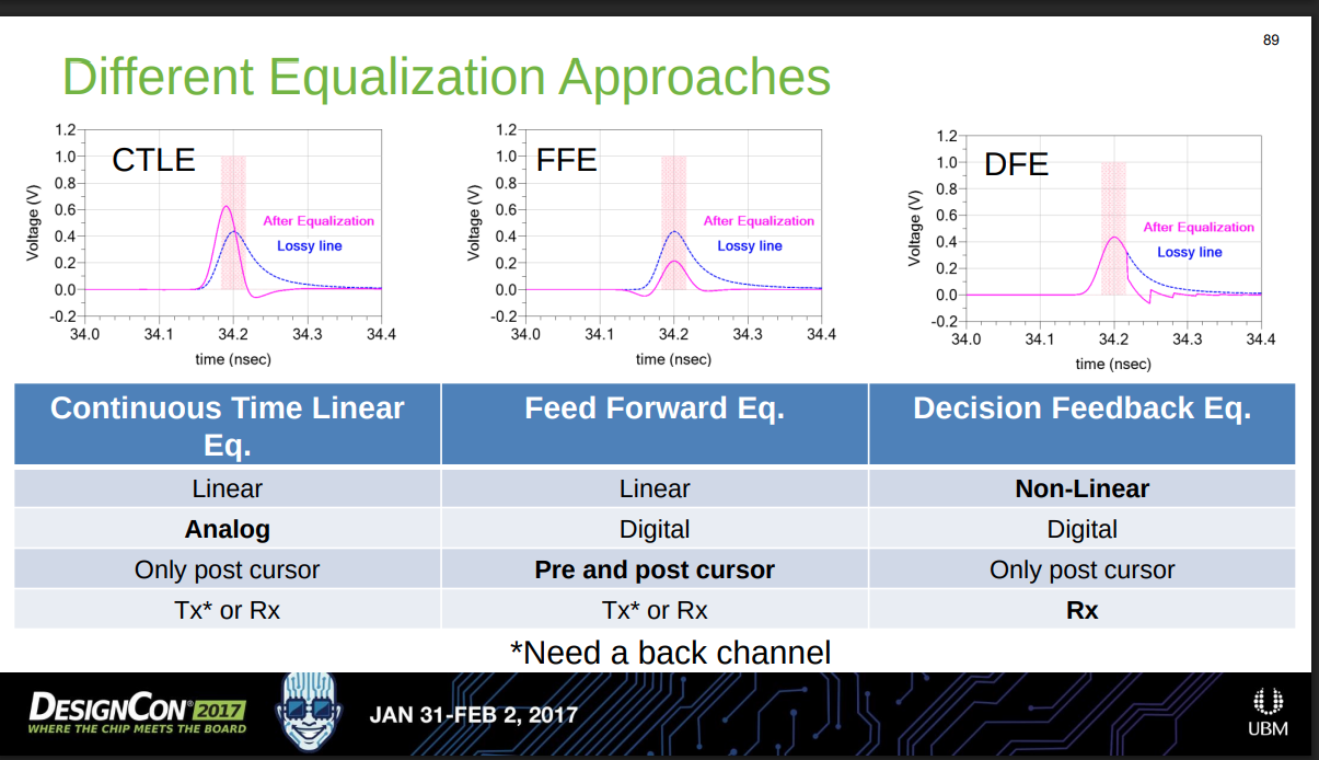
CTLE vs. FFE
Keysight Signal Integrity Educational Posts [Post 5: Root Cause of Eye Closure], [Post 6: Eye-opening Experience with CTLE], [Post 7: Eye-opening Experience with FFE]
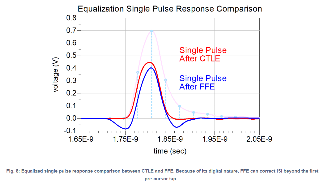
in the time domain
- CTLE provide only limited improvement in the pre-cursor ISI, because of the continuous-time, analog nature of CTLE
- FFE to reduce ISI in both the pre-cursor and post-cursor, because of operating digitally in discrete-time
in the frequency domain
- CTLE focuses on boosting frequency content at the Nyquist frequency
- FFE algorithm is selecting taps that effectively amplify the odd harmonics of the Nyquist frequency
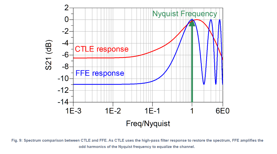
In the case of FFE, because of the nature of finite impulse response filter, we would expect amplification and attenuation of different harmonics of Nyquist Frequency
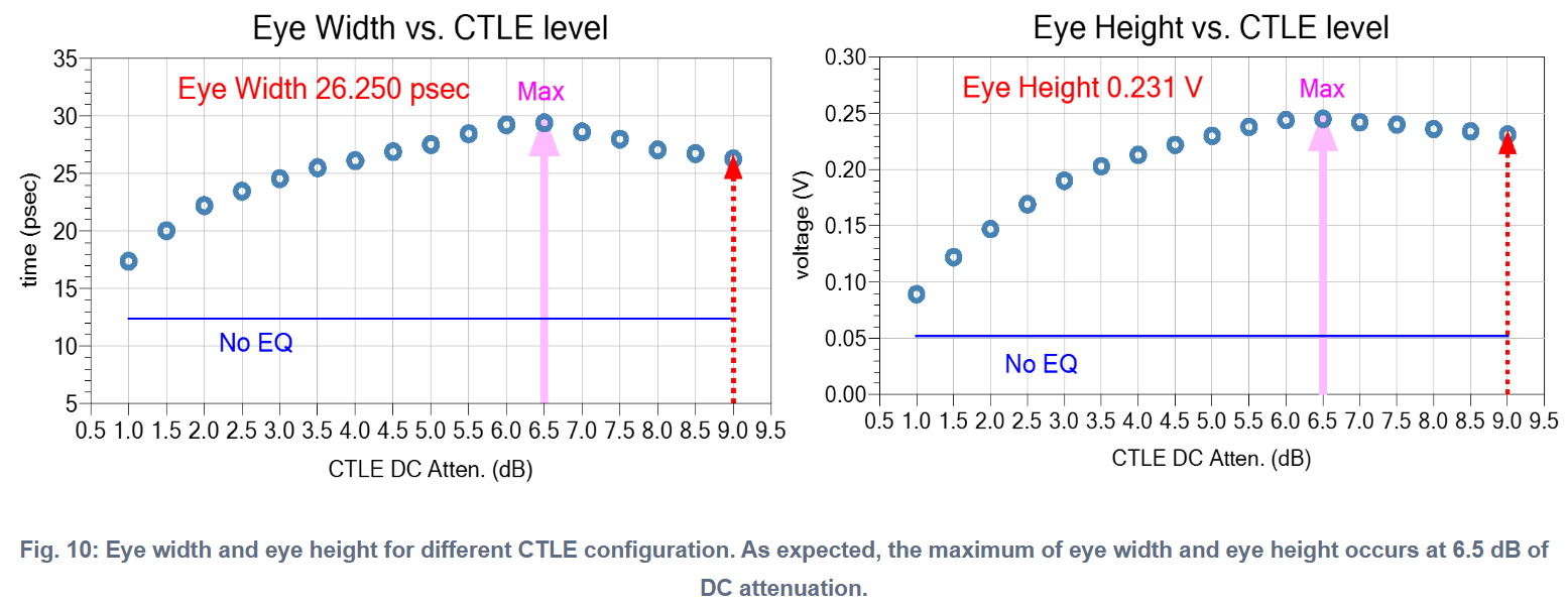
Until 6.5 dB of CTLE DC attenuation, the spread of the single pulse is positive and reaches almost zero at 6.5 dB. As the DC attenuation increases to more than 6.5 dB, the single pulse spectrum is restored too much, resulting in a negative dip at the end of the pulse
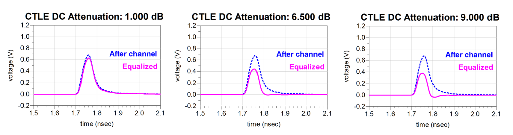
the maximum eye opening does not happen at maximum DC attenuation at 9 dB
DFE
Keysight Signal Integrity Educational Posts [Post 8: Eye-opening Experience with DFE]
There are kinks in the eye diagram, the signature of an opened DFE eye is different than other equalizations
DFE algorithm is reducing ISI based on the detected data (symbol)
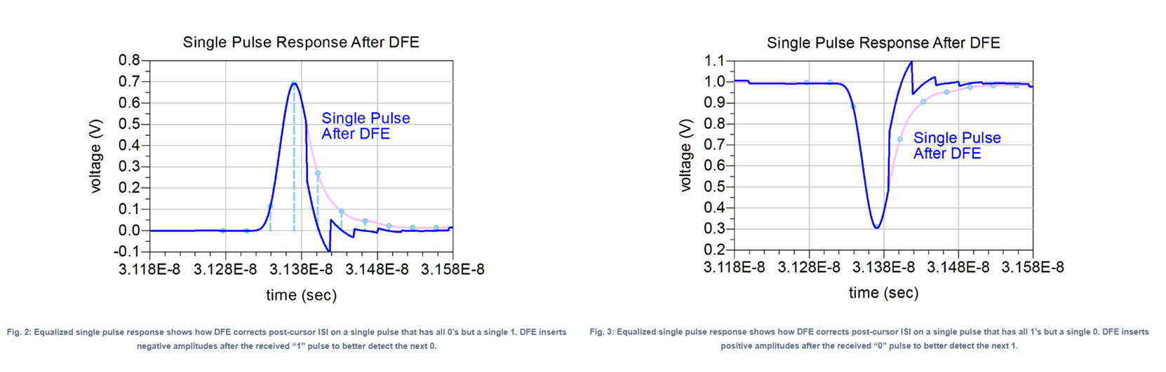
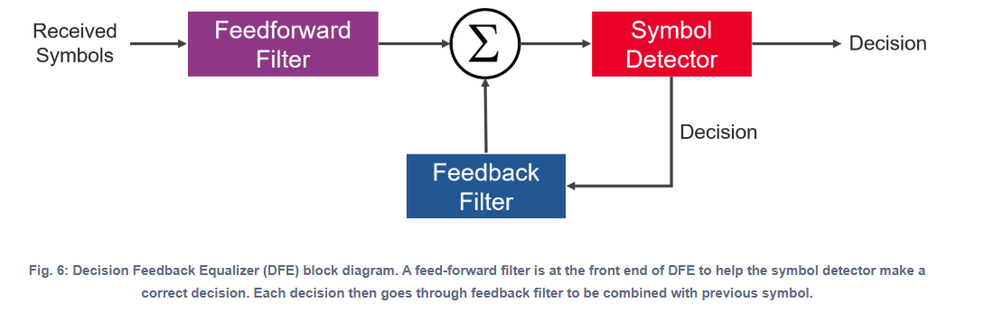
Since DFE assumes that past symbol decisions are correct. Incorrect decisions from the symbol detector corrupt the filtering of the feedback loop. As a result, the inclusion of the feedforward filter on the front end is crucial in minimizing the probability of error

- because symbol detection is nonlinear, decision feedback equalization is also nonlinear
- because of the nonlinearity of the DFE response, it must be modeled in the time domain
Intersymbol Interference (ISI)
L.W. Couch, Digital and Analog Communication Systems, 8th Edition, Pearson, 2013. [pdf]
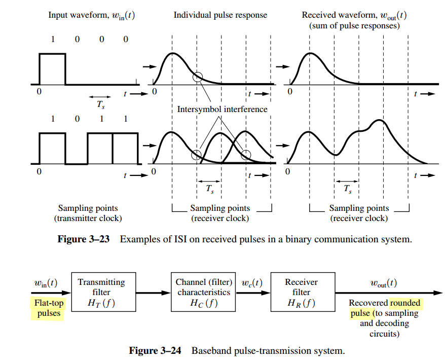
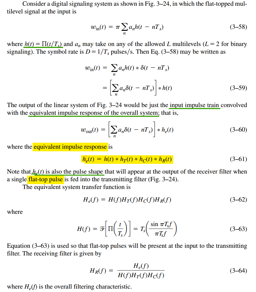
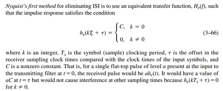
Nyquist discovered three different methods for pulse shaping that could be used to eliminate ISI
Nyquist's First Method (Zero ISI): physically unrealizable (i.e., the impulse response would be noncausal and of infinite duration), inaccurate sync will cause ISI
Nyquist's second method: allows some ISI to be introduced in a controlled way
Nyquist's third method: area under the \(h_e(t)\) pulse within the desired symbol interval, \(T_s\), is not zero, but the areas under \(h_e(t)\) in adjacent symbol intervals are zero
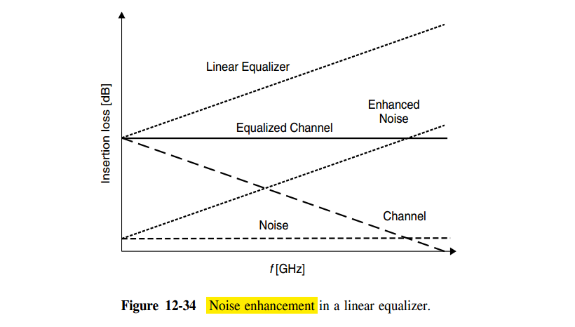
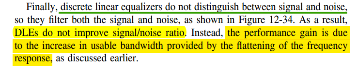
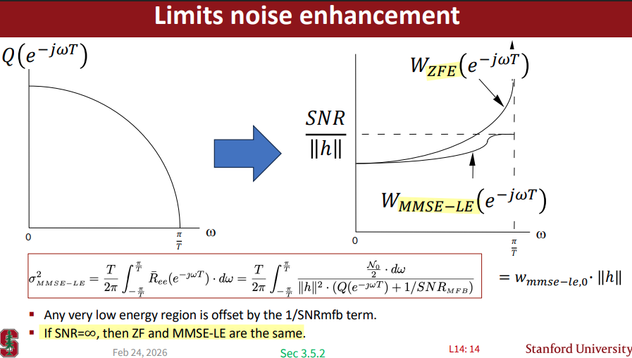
Noise Enhancement in Linear Equalizers
John M. Cioffi, Lecture 13, Thursday February 19th 2026 - Intersymbol Interference, MMSE, and SNR [https://cioffi-group.stanford.edu/ee379a/Lectures/L13.pdf]
—, Lecture 14, Tuesday February 24th 2026 - Linear Equalizers [https://cioffi-group.stanford.edu/ee379a/Lectures/L14.pdf]
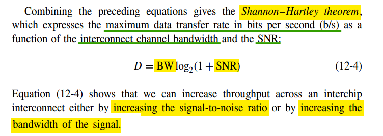
Shannon–Hartley theorem
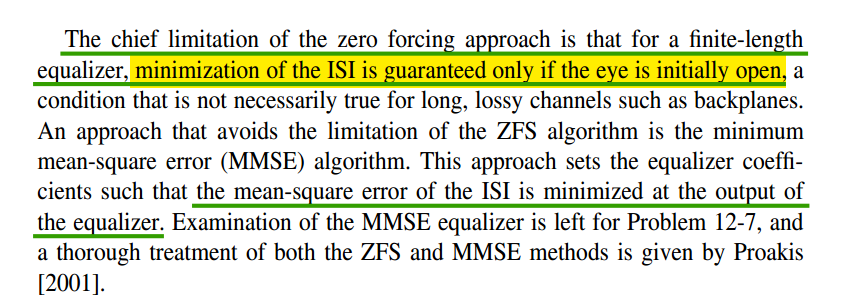
- ZFS eliminates the ISI only at the sampling points that correspond to the equalizer taps. The equalized pulse shows ISI in the intervals between the sample points and at sample points outside the equalizer
- The Minimum Mean-Square Error Linear Equalizer (MMSE-LE) balances ISI reduction and noise enhancement. The MMSE-LE always performs as well as, or better than, the ZFE
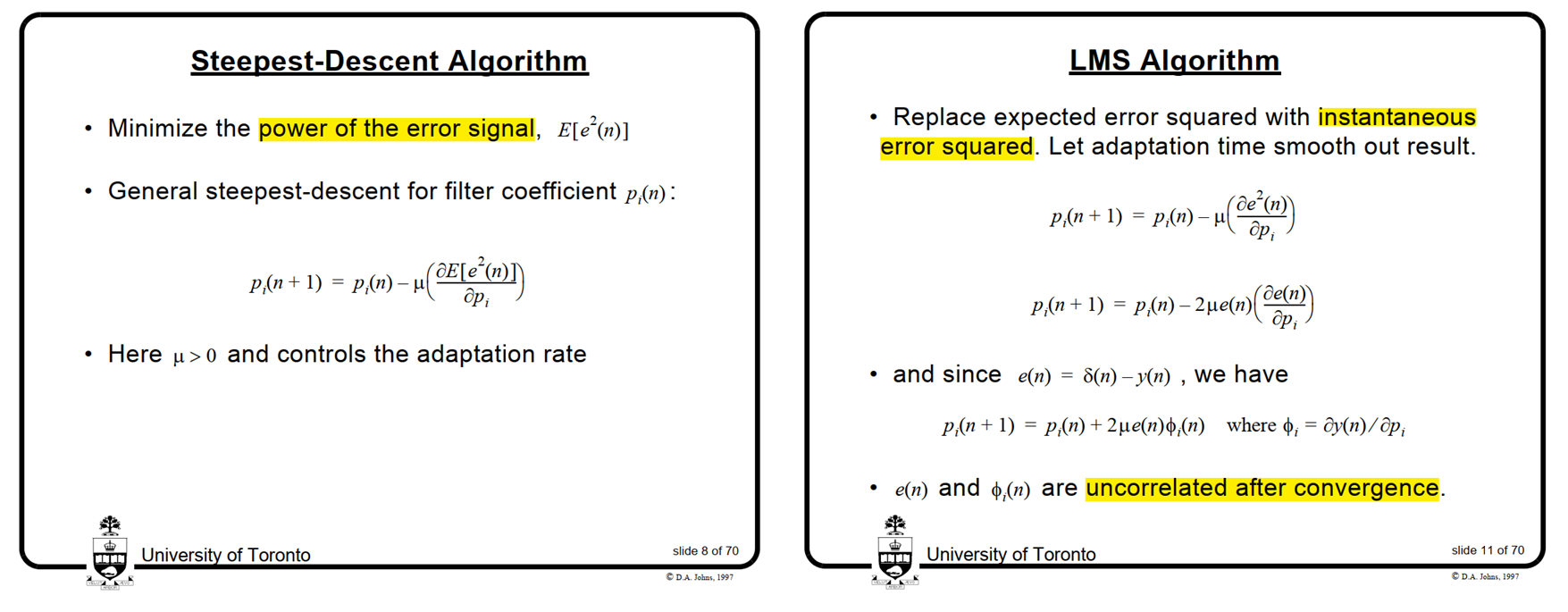
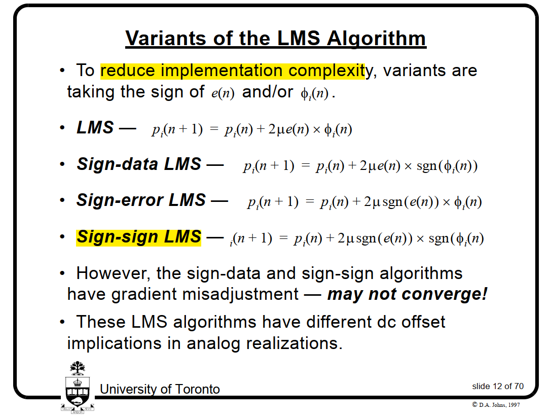
LMS (Least-Mean-Square) algorithm
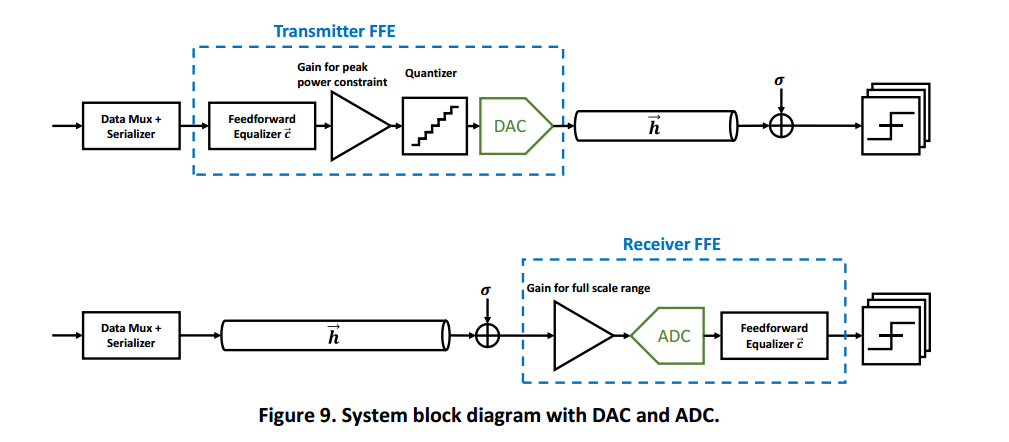
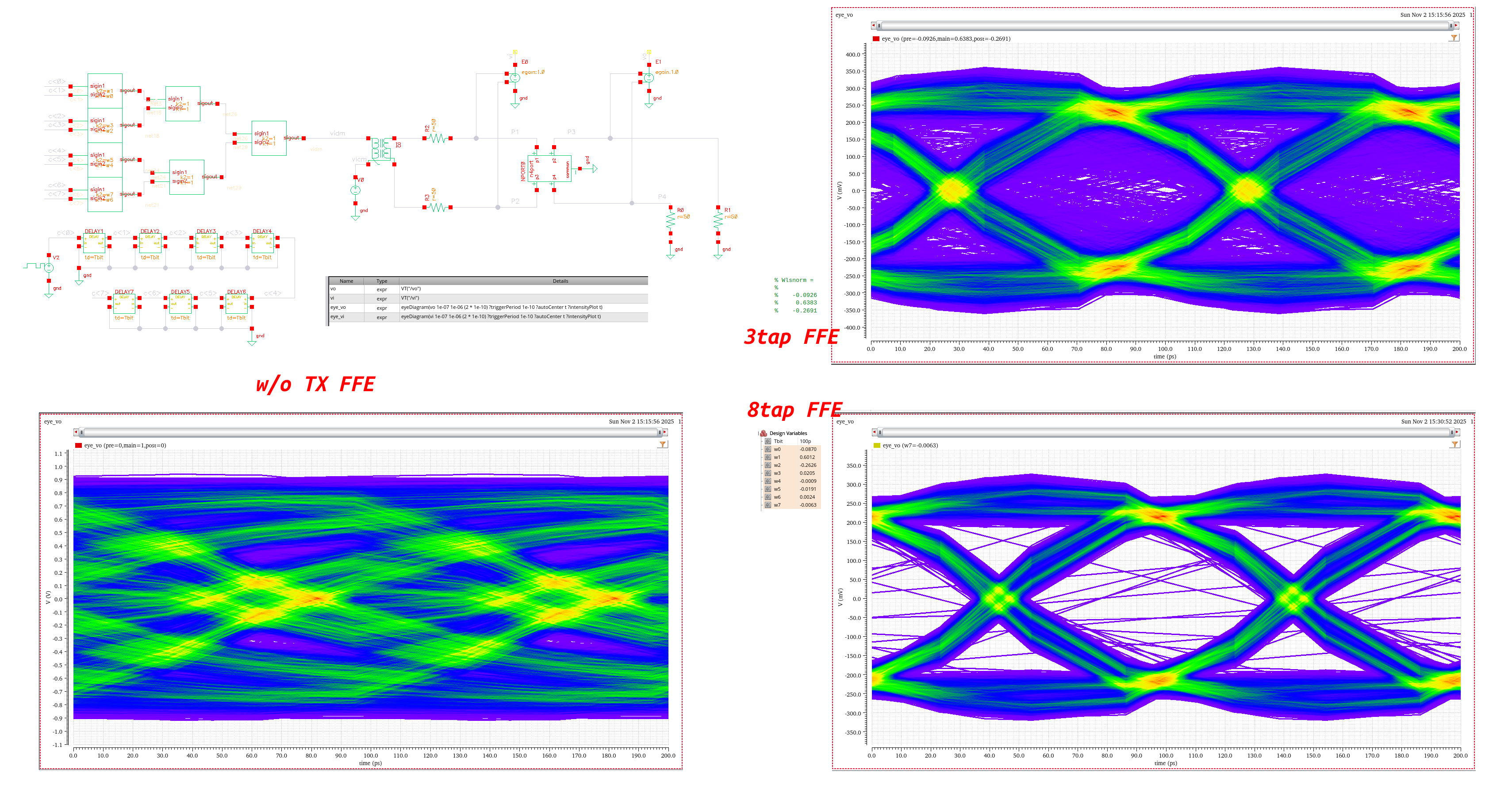
TX FFE
Jose E. Schutt-Aine, Spring 2024 ECE 546 Lecture - 27 Equalization [http://emlab.uiuc.edu/ece546/Lect_27.pdf]
Sam Palermo. Lecture 7 - Equalization Intro & TX FIR EQ [https://people.engr.tamu.edu/spalermo/ecen689/lecture7_ee720_eq_intro_txeq.pdf]
Vivek Telang, Equalization for High-Speed Serdes: System-level Comparison of Analog and Digital Techniques 2012 [https://ewh.ieee.org/r5/denver/sscs/Presentations/2012_08_Telang.pdf]
Kevin Zheng, Boris Murmann, Hongtao Zhang, and Geoff Zhang. Feedforward Equalizer Location Study for High-Speed Serial Systems [https://www.signalintegrityjournal.com/articles/1228-feedforward-equalizer-location-study-for-high-speed-serial-systems]
—, "System-Driven Circuit Design for ADC-Based Wireline Data Links", Ph.D. Dissertation, Stanford University, 2018 [https://purl.stanford.edu/hw458fp0168]
Hanumolu, P. K., Wei, G. Y., & Moon, Y. K. (2005). Equalizers for high-speed serial links. International Journal of High Speed Electronics and Systems [https://people.engr.tamu.edu/spalermo/ecen689/hslink_eq_overview_hanumolu_jhses05.pdf]
Gain Kim. Equalization, Architecture, and Circuit Design for High-Speed Serial Link Receiver [pdf]
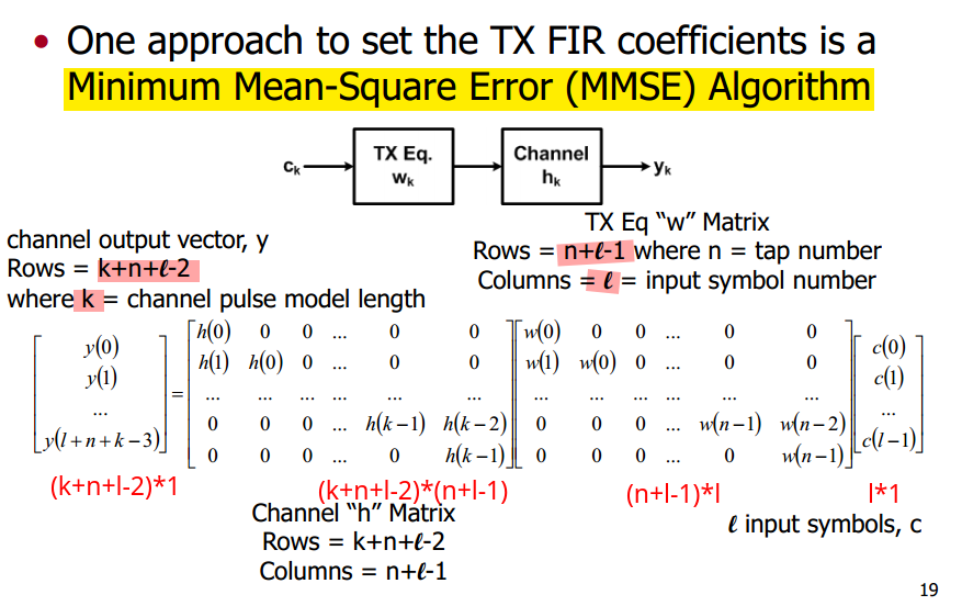
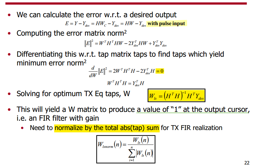
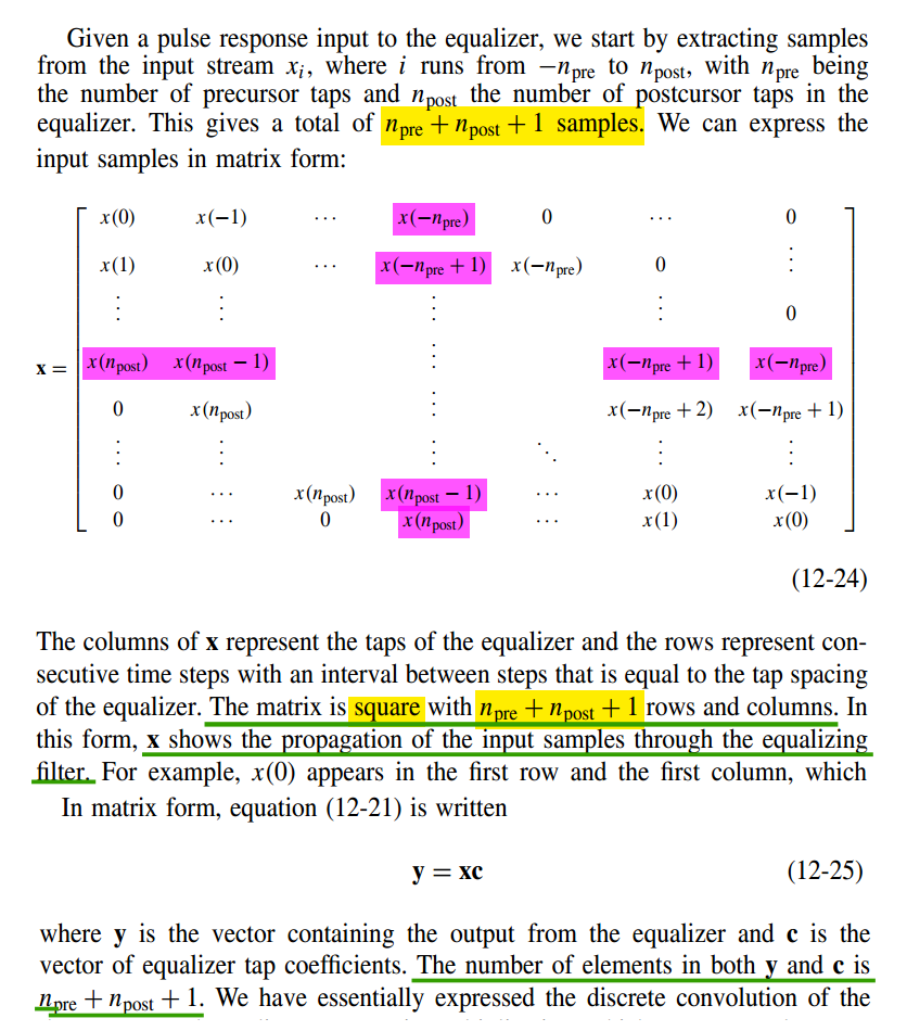
TX FIR Coefficient Selection with MMSE
Lecture 7: Equalization Introduction & TX FIR Eq [https://people.engr.tamu.edu/spalermo/ecen689/lecture7_ee720_eq_intro_txeq.pdf]

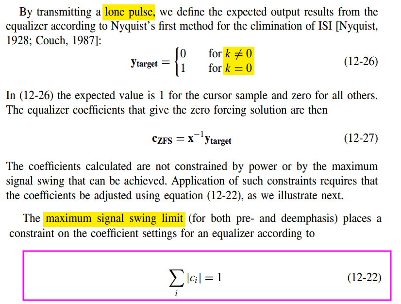
Lone-Pulse Equalization
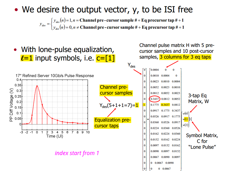

1 | h=[0.004, 0.0010, 0.0023, 0.0052, 0.0812, 0.3437, 0.1775, 0.0917, 0.0526,... |
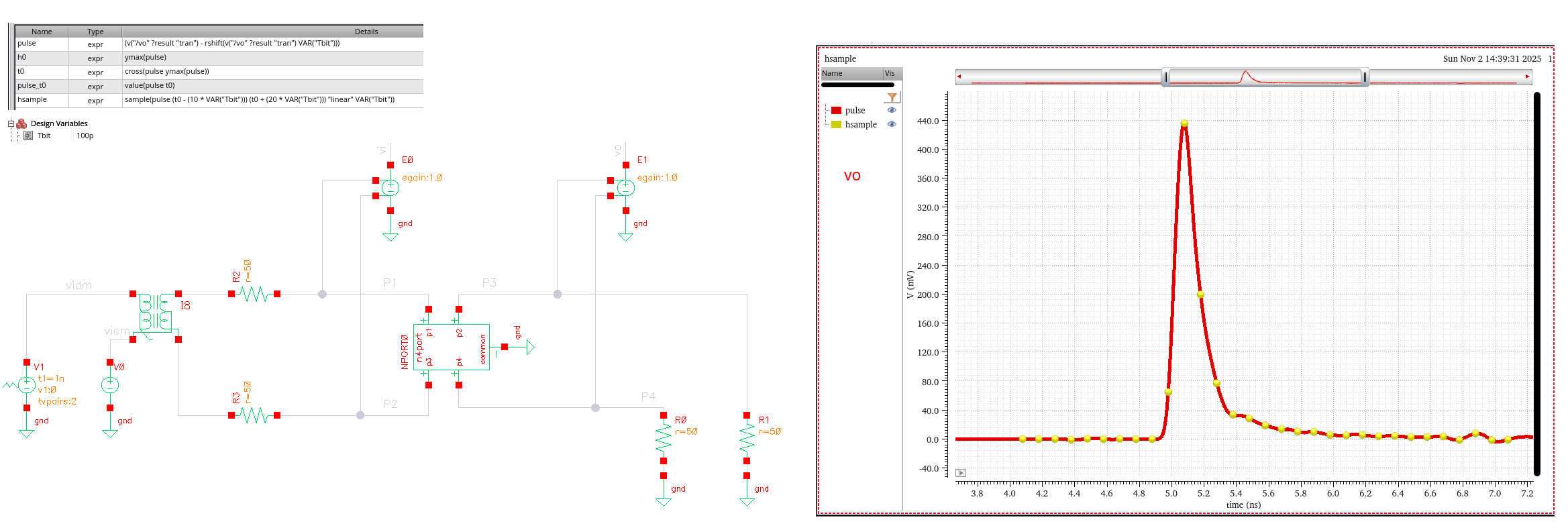
1 | fcsvf = readtable("hsample_pre10post20.csv"); |
TX FIR Coefficient Selection with ZFS
Zero Forcing Solution (ZFS)
| \(k=-\text{npre}\) | \(k=0\); \(y_\text{target}=1\) | \(k=\text{npost}\) | |
|---|---|---|---|
| \(c_{-\text{npre}}\) | \(x_0\) | 0 | |
| \(c_{-\text{npre}+1}\) | \(x_{-1}\) | 0 | |
| ... | ... | ... | ... |
| \(c_0\) | \(x_{-\text{npre}}\) | \(x_0\) | \(x_{\text{npost}}\) |
| ... | ... | ... | ... |
| \(c_{\text{npost}-1}\) | \(0\) | \(x_1\) | |
| \(c_{\text{npost}}\) | \(0\) | \(x_0\) |
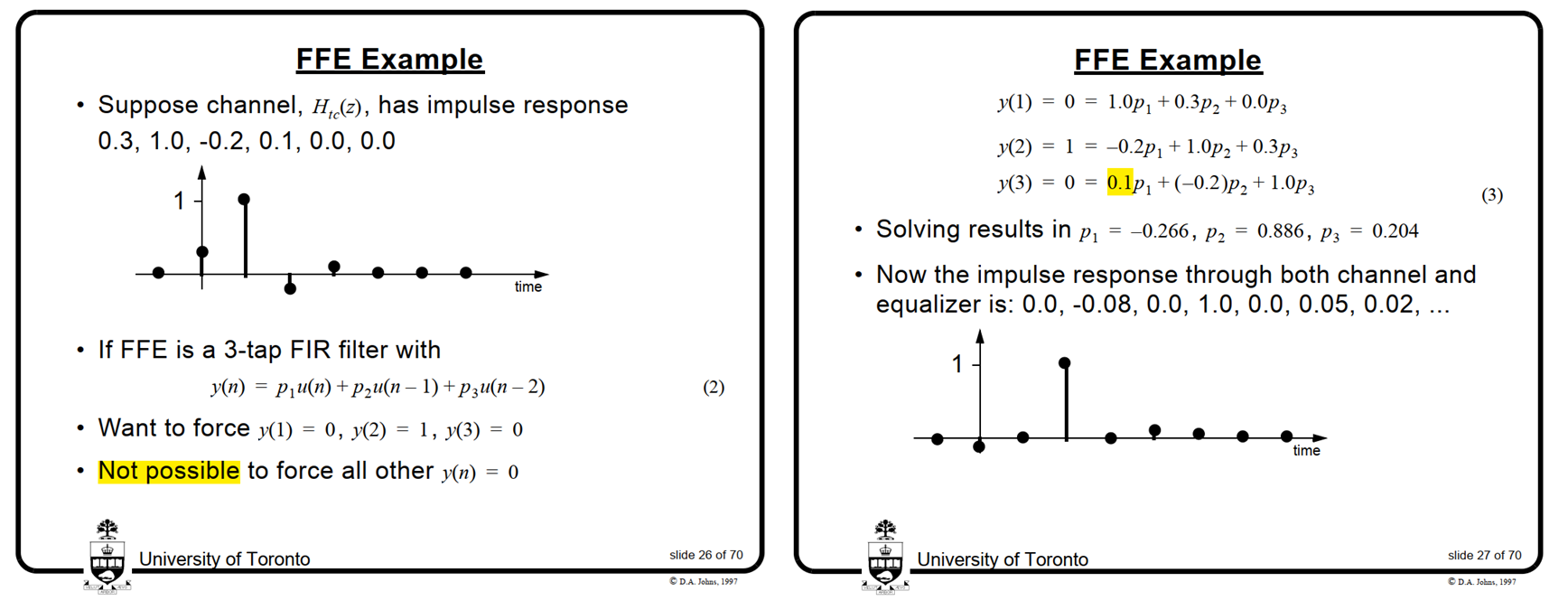
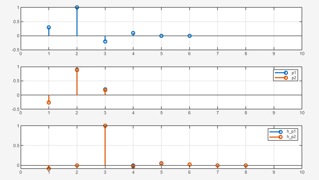
1 | ht = [0.3, 1.0, -0.2, 0.1, 0.0, 0.0]; |
TX FIR Adaptation Algorithm
Sam Palermo. ECEN720: High-Speed Links Circuits and Systems Spring 2025 Lecture 8: RX FIR, CTLE, DFE, & Adaptive Eq. [https://people.engr.tamu.edu/spalermo/ecen689/lecture8_ee720_rx_adaptive_eq.pdf]
TODO 📅
RX FFE
TODO 📅
MMSE-based algorithms
minimum mean squared error (MMSE)
There are three major MMSE-based algorithms:
- least mean square (LMS),
- normalized least mean square (NLMS)
- recursive least square (RLS)
LMS (Least-Mean-Square)
This simplified version of LMS algorithm is identical to the zero-forcing algorithm which minimizes the ISI at data samples
Sign-Sign LMS (SS-LMS)
B. Kim, "Tutorial: Basics of Equalization Techniques: Channels, Equalization, and Circuits," 2022 IEEE International Solid-State Circuits Conference (ISSCC), San Francisco, CA, USA, 2022
V. Stojanovic et al., "Autonomous dual-mode (PAM2/4) serial link transceiver with adaptive equalization and data recovery," in IEEE Journal of Solid-State Circuits, vol. 40, no. 4, pp. 1012-1026, April 2005, [https://sci-hub.ru/10.1109/JSSC.2004.842863]
Jinhyung Lee, Design of High-Speed Receiver for Video Interface with Adaptive Equalization; Phd thesis, August 2019. [thesis link]
Paulo S. R. Diniz, Adaptive Filtering: Algorithms and Practical Implementation, 5th edition
E. -H. Chen et al., "Near-Optimal Equalizer and Timing Adaptation for I/O Links Using a BER-Based Metric," in IEEE Journal of Solid-State Circuits, vol. 43, no. 9, pp. 2144-2156, Sept. 2008 [https://sci-hub.ru/10.1109/JSSC.2008.2001871]
DFE h0 Estimator
summer output \[ r_k = a_kh_0+\left(\sum_{n=-\infty,n\neq0}^{+\infty}a_{k-n}h_n-\sum_{n=1}^{\text{ntap}}\hat{a}_{k-n}\hat{h}_n\right) \] error slicer analog output \[ e_k=r_k-\hat{a}_k \hat{h}_0 \] error slicer digital output \[ \hat{e}_k=|e_k| \] It's NOT possible to implement \(e_k\), which need to determine \(\hat{a}_k=|r_k|\) in no time. One method to approach this problem is calculate \(e_k^{a_k=1}=r_k-\hat{a}_k \hat{h}_0\) and \(e_k^{a_k=-1}=r_k+\hat{a}_k \hat{h}_0\), then select the right one based on \(\hat{a}_k\)
The update equation based on Sign-Sign-Least Mean square (SS-LMS) and loss function \(L(\hat{h}_{\text{0~ntap}})=E(e_k^2)\) \[ \hat{h}_n(k+1) = \hat{h}_n(k)+\mu \cdot |e_k|\cdot \hat{a}_{k-n} \] Where \(n \in [0,...,\text{ntap}]\). This way, we can obtain \(\hat{h}_0\), \(\hat{h}_1\), \(\hat{h}_2\), ...
\(\hat{h}_0\) is used in AFE adaptation
We may encounter difficulty if the first tap of DFE is unrolled, its \(e_k\) is modified as follow \[ r_k = a_kh_0+\left(\sum_{n=-\infty,n\neq0}^{+\infty}a_{k-n}h_n-\sum_{n=2}^{\text{ntap}}\hat{a}_{k-n}\hat{h}_n\right) \] Where there is NO \(\hat{h}_1\)
To find \(\hat{h}_1\), we shall use different pattern for even and odd error slicer
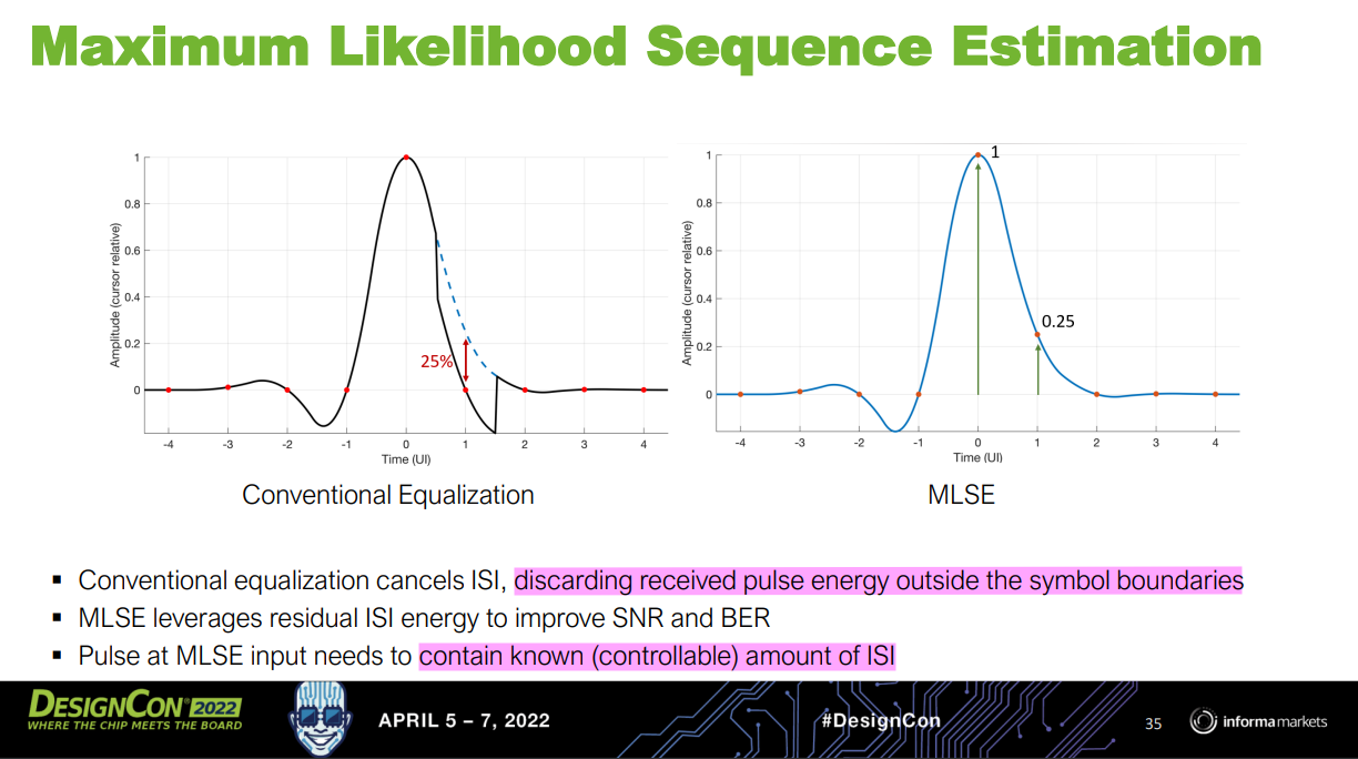
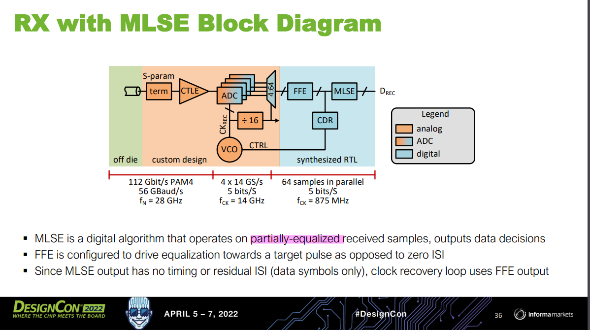
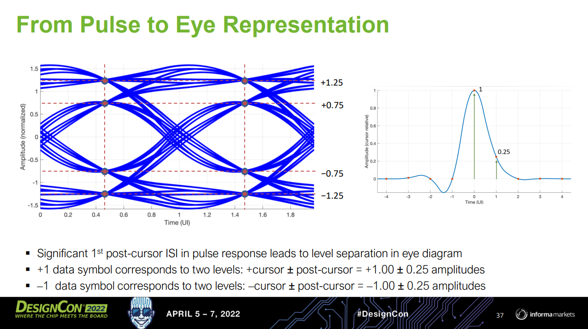
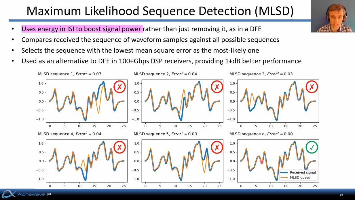
MLSD (Maximum Likelihood Sequence Detection)
The process is also referred to as Maximum Likelihood Sequence Estimator (MLSE)
[IBIS-AMI Modeling and Correlation Methodology for ADC-Based SerDes Beyond 100 Gb/s https://static1.squarespace.com/static/5fb343ad64be791dab79a44f/t/63d807441bcd266de258b975/1675102025481/SLIDES_Track02_IBIS_AMI_Modeling_and_Correlation_Tyshchenko.pdf]
M. Emami Meybodi, H. Gomez, Y. -C. Lu, H. Shakiba and A. Sheikholeslami, "Design and Implementation of an On-Demand Maximum-Likelihood Sequence Estimation (MLSE)," in IEEE Open Journal of Circuits and Systems, vol. 3, pp. 97-108, 2022, doi: 10.1109/OJCAS.2022.3173686.
Zaman, Arshad Kamruz (2019). A Maximum Likelihood Sequence Equalizing Architecture Using Viterbi Algorithm for ADC-Based Serial Link. Undergraduate Research Scholars Program. Available electronically from [https://hdl.handle.net/1969.1/166485]
There are several variants of MLSD (Maximum Likelihood Sequence Detection), including:
- Viterbi Algorithm
- Decision Feedback Sequence Estimation (DFSE)
- Soft-Output MLSD
[Evolution Of Equalization Techniques In High-Speed SerDes For Extended Reaches. https://semiengineering.com/evolution-of-equalization-techniques-in-high-speed-serdes-for-extended-reaches/]
S. Song, K. D. Choo, T. Chen, S. Jang, M. P. Flynn and Z. Zhang, "A Maximum-Likelihood Sequence Detection Powered ADC-Based Serial Link," in IEEE Transactions on Circuits and Systems I: Regular Papers, vol. 65, no. 7, pp. 2269-2278, July 2018
[http://contents.kocw.or.kr/document/lec/2012/Korea/KoYoungChai/33.pdf]
David Johns. Partial Response and Viterbi Detecti [https://www.eecg.utoronto.ca/~johns/ece1392/slides/partial_response.pdf]
Leslie Rusch. [https://wcours.gel.ulaval.ca/GEL7114/assets/pdfs/Module4_en_1by1_1.pdf]
Vineel Kumar Veludandi. Maximum likelihood sequence estimation (MLSE) using the Viterbi algorithm [https://github.com/vineel49/mlse]
Bang-Bang CDR
alexander PD or !!PD
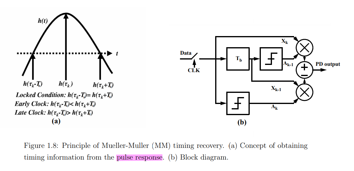
The alexander PD locks that edge clock (clkedge) is located at zero crossings of the data. The \(h_{-0.5}\) and \(h_{0.5}\) are equal at the lock point, where the \(h_{-0.5}\) and \(h_{0.5}\) are the cursors located at -0.5 UI and 0.5 UI.
Kwangho Lee, "Design of Receiver with Offset Cancellation of Adaptive Equalizer and Multi-Level Baud-Rate Phase Detector" [https://s-space.snu.ac.kr/bitstream/10371/177584/1/000000167211.pdf]
Shahramian, Shayan, "Adaptive Decision Feedback Equalization With Continuous-time Infinite Impulse Response Filters" [https://tspace.library.utoronto.ca/bitstream/1807/77861/3/Shahramian_Shayan_201606_PhD_thesis.pdf]
MENIN, DAVIDE, "Modelling and Design of High-Speed Wireline Transceivers with Fully-Adaptive Equalization" [https://air.uniud.it/retrieve/e27ce0ca-15f7-055e-e053-6605fe0a7873/Modelling%20and%20Design%20of%20High-Speed%20Wireline%20Transceivers%20with%20Fully-Adaptive%20Equalization.pdf]
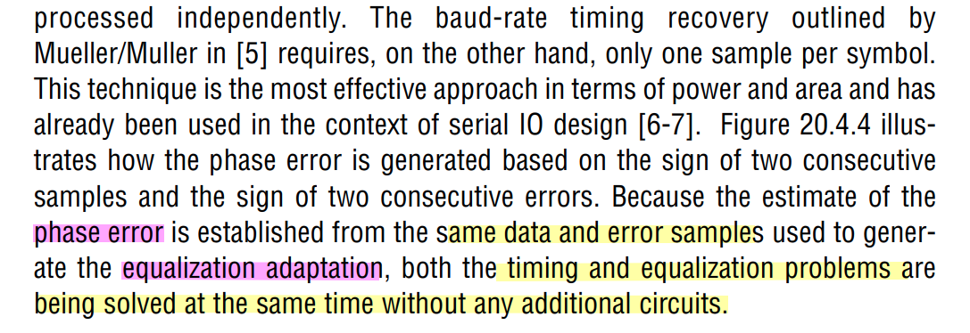
Mueller-Muller CDR
Faisal A. Musa. "HIGH-SPEED BAUD-RATE CLOCK RECOVERY" [https://www.eecg.utoronto.ca/~tcc/thesis-musa-final.pdf]
Faisal A. Musa."CLOCK RECOVERY IN HIGH-SPEED MULTILEVEL SERIAL LINKS" [https://www.eecg.utoronto.ca/~tcc/faisal_iscas03.pdf]
Eduardo Fuentetaja. "Analysis of the M&M Clock Recovery Algorithm" [https://edfuentetaja.github.io/sdr/m_m_analysis/]
Liu, Tao & Li, Tiejun & Lv, Fangxu & Liang, Bin & Zheng, Xuqiang & Wang, Heming & Wu, Miaomiao & Lu, Dechao & Zhao, Feng. (2021). Analysis and Modeling of Mueller-Muller Clock and Data Recovery Circuits. Electronics. 10. 1888. 10.3390/electronics10161888.
Gu, Youzhi & Feng, Xinjie & Chi, Runze & Chen, Yongzhen & Wu, Jiangfeng. (2022). Analysis of Mueller-Muller Clock and Data Recovery Circuits with a Linearized Model. 10.21203/rs.3.rs-1817774/v1.
Baud-Rate CDRs [https://ocw.snu.ac.kr/sites/default/files/NOTE/Lec%206%20-%20Clock%20and%20Data%20Recovery.pdf]
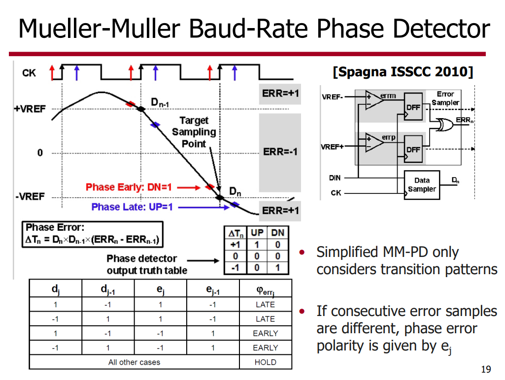
F. Spagna et al., "A 78mW 11.8Gb/s serial link transceiver with adaptive RX equalization and baud-rate CDR in 32nm CMOS," 2010 IEEE International Solid-State Circuits Conference - (ISSCC), San Francisco, CA, USA, 2010, pp. 366-367, [https://sci-hub.ru/10.1109/ISSCC.2010.5433823]
K. Yadav, P. -H. Hsieh and A. C. Carusone, "Loop Dynamics Analysis of PAM-4 Mueller–Muller Clock and Data Recovery System," in IEEE Open Journal of Circuits and Systems, vol. 3, pp. 216-227, 2022 [https://ieeexplore.ieee.org/stamp/stamp.jsp?arnumber=9910561]
Jaeduk Han, "Design and Automatic Generation of 60Gb/s Wireline Transceivers" [https://www2.eecs.berkeley.edu/Pubs/TechRpts/2019/EECS-2019-143.pdf]
Sam Palermo, ECEN720: High-Speed Links Circuits and Systems Spring 2025. Lecture 12: CDRs [https://people.engr.tamu.edu/spalermo/ecen689/lecture12_ee720_cdrs.pdf]
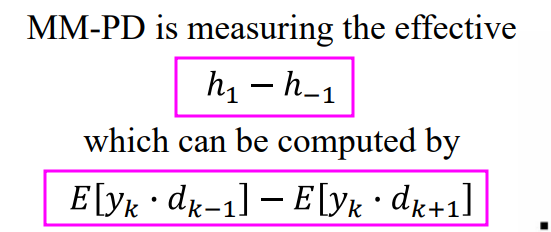
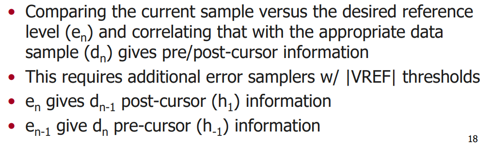
Suppose 1-precursor, 1-postcursor — \(y_k = d_{k-1}h_1 + d_k h_0 + d_{k+1}h_{-1}\) \[ \color{magenta}E[y_k\cdot d_{k-1}] - E[y_k\cdot d_{d+1}] = E[|d_{k-1}|^2h_{1}] - E[|d_{k+1}|^2h_{-1}] =h_1-h_{-1} \] MMPD infers the channel response from baud-rate samples of the received data, the adaptation aligns the sampling clock such that pre-cursor is equal to the post-cursor in the pulse response
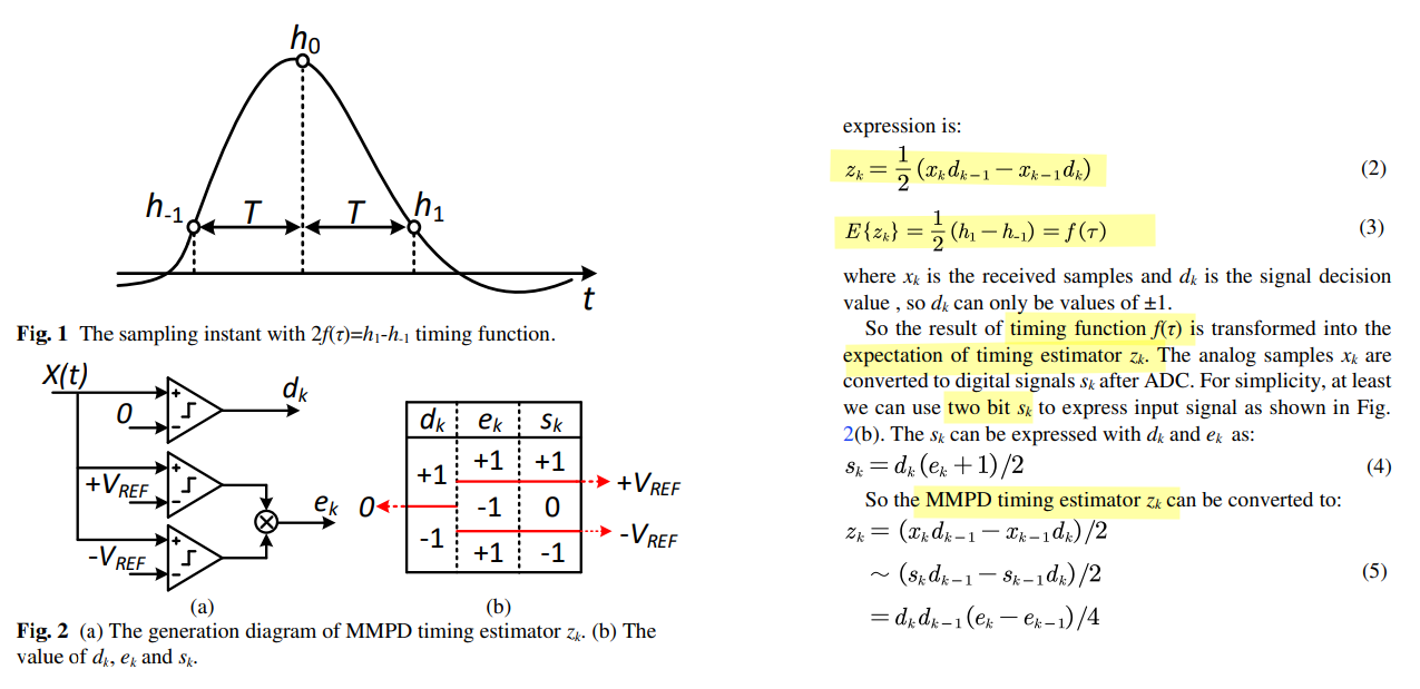
Suppose \(x_k = d_{k-1}h_1 + d_k h_0 +
d_{k+1}h_{-1}\) and \(x_{k-1} =
d_{k-2}h_1 + d_{k-1} h_0 + d_{k}h_{-1}\) \[
\color{magenta}E\{z_k\} = \frac{1}{2} E\{|d_{k-1}|^2h_1\} - \frac{1}{2}
E\{|d_{k}|^2h_{-1}\} = \frac{1}{2}(h_1 - h_{-1})
\] 
Mueller-Muller PD
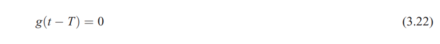
Mueller-Muller type A timing function
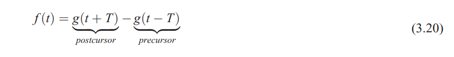
Mueller-Muller type B timing function
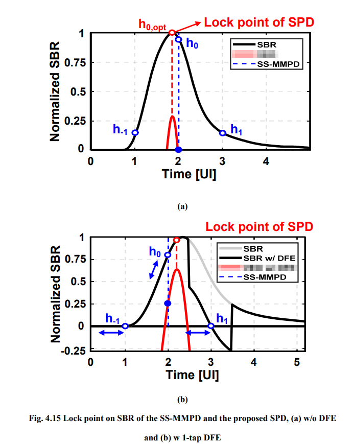
SS-MM CDR
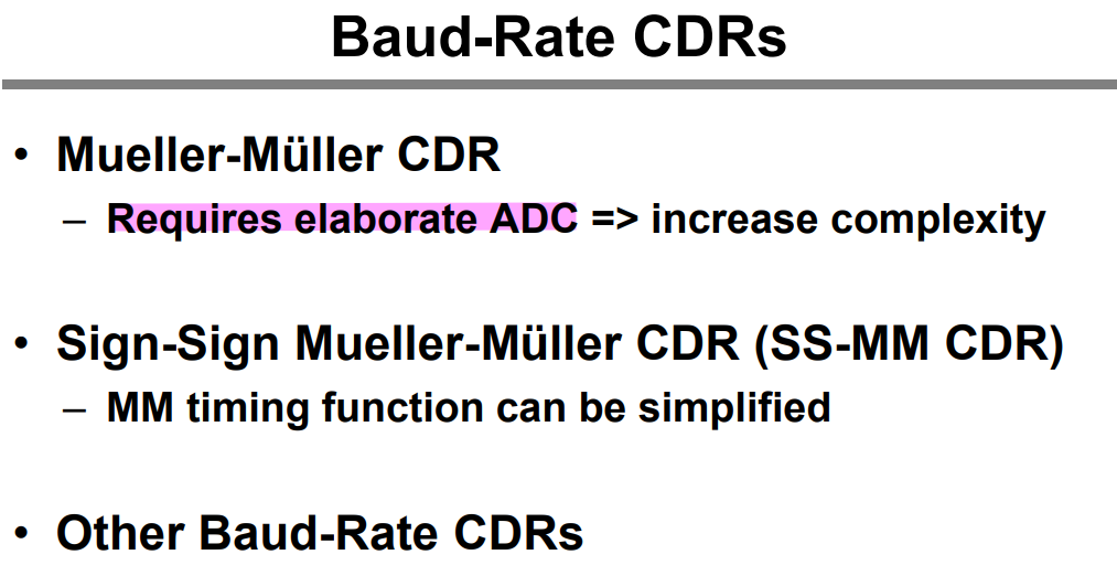
\(h_1\) is necessary
without DFE
SS-MMPD locks at the point (\(h_1=h_{-1}\))
With a 1-tap DFE
1-tap adaptive DFE that forces the \(h_1\) to be zero, the SS-MMPD locks wherever the \(h_{-1}\) is zero and drifts eventually.
Consequently, it suffers from a severe multiple-locking problem with an adaptive DFE
Kwangho Lee, "Design of Receiver with Offset Cancellation of Adaptive Equalizer and Multi-Level Baud-Rate Phase Detector" [https://s-space.snu.ac.kr/bitstream/10371/177584/1/000000167211.pdf]
Pattern filter
| pattern | main cursor |
|---|---|
| 011 | \(s_{011}=-h_1+h_0+h_{-1}\) |
| 110 | \(s_{110}=h_1+h_0-h_{-1}\) |
| 100 | \(s_{100}=h_1-h_0-h_{-1}\) |
| 001 | \(s_{001}=-h_1-h_0+h_{-1}\) |
During adapting, we make
- \(s_{011}\) & \(s_{110}\) are approaching to each other
- \(s_{100}\) & \(s_{001}\) are approaching to each other
Then, \(h_{-1}\) and \(h_1\) are same, which is desired
reference
Barry, John R., Edward A. Lee, and David G. Messerschmitt. Digital communication. Springer, 2003.
Hall, Stephen H., and Howard L. Heck. Advanced Signal Integrity for High-speed Digital Designs. Wiley : IEEE, 2009 [pdf]
Oh, Kyung, and Xing Yuan. High-Speed Signaling: Jitter Modeling, Analysis, and Budgeting. 1st edition. Prentice Hall, 2011. [pdf]
John M. Cioffi, Chapter 3 - Equalization [https://cioffi-group.stanford.edu/doc/book/chap3.pdf]
Proakis, John G., and Masoud Salehi. Digital Communications. 5th ed. McGraw-Hill, 2008. [pdf]
David Johns. ECE1392H - Integrated Circuits for Digital Communications - Fall 2001: [Equalization], [Timing Recovery]
Stojanovic, Vladimir & Ho, A. & Garlepp, B. & Chen, Fred & Wei, J. & Alon, Elad & Werner, C. & Zerbe, J. & Horowitz, M.A.. (2004). Adaptive equalization and data recovery in a dual-mode (PAM2/4) serial link transceiver. IEEE Symposium on VLSI Circuits, Digest of Technical Papers. 348 - 351. [https://sci-hub.ru/10.1109/VLSIC.2004.1346611]
A. A. Bazargani, H. Shakiba and D. A. Johns, "MMSE Equalizer Design Optimization for Wireline SerDes Applications," in IEEE Transactions on Circuits and Systems I: Regular Papers [https://www.eecg.utoronto.ca/~johns/nobots/papers/pdf/2024_bazaragani.pdf]
Masum Hossain, ISSCC2023 T11: "Digital Equalization and Timing Recovery Techniques for ADC-DSP-based Highspeed Links" [https://www.nishanchettri.com/isscc-slides/2023%20ISSCC/TUTORIALS/T11.pdf]
—, "LOW POWER DIGITAL EQUALIZATION FOR HIGH SPEED SERDES" [https://www.ieeetoronto.ca/wp-content/uploads/2020/06/SSCS_invited_talk.pdf]
A. Sharif-Bakhtiar, A. Chan Carusone, "A Methodology for Accurate DFE Characterization," IEEE RFIC Symposium, Philadelphia, Pennsylvania, June 2018. [PDF] [Slides – PDF]
Tony Chan Carusone. High Speed Communications Part 11 – SerDes DSP Interactions [https://youtu.be/YIAwLskuVPc]
—, 2022 Optimization Tools for Future Wireline Transceivers [https://www.ieeetoronto.ca/wp-content/uploads/2022/12/UofT-Future-of-Wireline-Workshop-2022.pdf]
Alphawave IP CEO. How DSP is Killing the Analog in SerDes [https://youtu.be/OY2Dn4EDPiA]
S. Kiran, S. Cai, Y. Zhu, S. Hoyos and S. Palermo, "Digital Equalization With ADC-Based Receivers: Two Important Roles Played by Digital Signal Processingin Designing Analog-to-Digital-Converter-Based Wireline Communication Receivers," in IEEE Microwave Magazine, vol. 20, no. 5, pp. 62-79, May 2019 [https://sci-hub.se/10.1109/MMM.2019.2898025]
K. K. Parhi, "Design of multigigabit multiplexer-loop-based decision feedback equalizers," in IEEE Transactions on Very Large Scale Integration (VLSI) Systems, vol. 13, no. 4, pp. 489-493, April 2005 [http://sci-hub.se/10.1109/TVLSI.2004.842935]
T. Toifl et al., "A 3.5pJ/bit 8-tap-feed-forward 8-tap-decision feedback digital equalizer for 16Gb/s I/Os," ESSCIRC 2014 - 40th European Solid State Circuits Conference (ESSCIRC), Venice Lido, Italy, 2014 [https://sci-hub.se/10.1109/ESSCIRC.2014.6942120]
Daniel Friedman, 2018 Considerations and Implementations for High data Rate Serial Link Design [https://www.ieeetoronto.ca/wp-content/uploads/2020/06/DL-Toronto-Nov-2018.pdf]
Cathy Ye Liu, Broadcom Inc. DesignCon 2019: 100+ Gb/s Ethernet Forward Error Correction (FEC) Analysis
—, Broadcom Inc. DesignCon 2024: 200+ Gbps Ethernet Forward Error Correction (FEC) Analysis
Tony Chan Carusone Integrated Systems Laboratory, University of Toronto [https://isl.utoronto.ca/publications/]
Tony Chan Carusone 2022. Optimization Tools for Future Wireline Transceivers [https://www.ieeetoronto.ca/wp-content/uploads/2022/12/UofT-Future-of-Wireline-Workshop-2022.pdf]
Aleksey Tyshchenko, SeriaLink Systems Clinton Walker, Alphawave IP. DesignCon 2022. IBIS-AMI Modeling and Correlation Methodology for ADC-Based SerDes Beyond 100 Gb/s [https://static1.squarespace.com/static/5fb343ad64be791dab79a44f/t/63d807441bcd266de258b975/1675102025481/SLIDES_Track02_IBIS_AMI_Modeling_and_Correlation_Tyshchenko.pdf]
[https://ibis.org/summits/apr22/tyshchenko.pdf]
Ali Sheikholeslami Electronics Group, University of Toronto [https://www.eecg.utoronto.ca/~ali/]
Keshab K. Parhi [http://www.ece.umn.edu/users/parhi/]
Tinoosh Mohsenin. CMPE 691: Digital Signal Processing Hardware Implementation [https://userpages.cs.umbc.edu/tinoosh/cmpe691/]
Qasim Chaudhari. Maximum Likelihood Estimation of Clock Offset [https://wirelesspi.com/maximum-likelihood-estimation-of-clock-offset/]
—. Channel Estimation in Wireless Communication. [https://wirelesspi.com/channel-estimation-in-wireless-communication/]
—. Phase Locked Loop (PLL) in a Software Defined Radio (SDR) [https://wirelesspi.com/phase-locked-loop-pll-in-a-software-defined-radio-sdr/]
—. Phase Locked Loop (PLL) for Symbol Timing Recovery [https://wirelesspi.com/phase-locked-loop-pll-for-symbol-timing-recovery/]
—. How Decision Feedback Equalizers (DFE) Work [https://wirelesspi.com/how-decision-feedback-equalizers-dfe-work/]
—. Maximum Likelihood Sequence Estimation (MLSE Equalizer) [https://wirelesspi.com/maximum-likelihood-sequence-estimation-mlse-equalizer/]
—. Least Mean Square (LMS) Equalizer – A Tutorial [https://wirelesspi.com/least-mean-square-lms-equalizer-a-tutorial/]
—. Early-Late Bit Synchronizer in Digital Communication [https://wirelesspi.com/early-late-bit-synchronizer-in-digital-communication/]
—. Gardner Timing Error Detector: A Non-Data-Aided Version of Zero-Crossing Timing Error Detectors [https://wirelesspi.com/gardner-timing-error-detector-a-non-data-aided-version-of-zero-crossing-timing-error-detectors/]
—. Mueller and Muller Timing Synchronization Algorithm [https://wirelesspi.com/mueller-and-muller-timing-synchronization-algorithm/]
—. Digital Filter and Square Timing Recovery [https://wirelesspi.com/digital-filter-and-square-timing-recovery/]
—. What is a Symbol Timing Offset and How It Distorts the Rx Signal [https://wirelesspi.com/what-is-a-symbol-timing-offset-and-how-it-distorts-the-rx-signal/]
—. How Automatic Gain Control (AGC) Works [https://wirelesspi.com/how-automatic-gain-control-agc-works/]
Hongtao Zhang, DesignCon 2016. PAM4 Signaling for 56G Serial Link Applications − A Tutorial [https://www.xilinx.com/publications/events/designcon/2016/slides-pam4signalingfor56gserial-zhang-designcon.pdf]