Charge pumps & capacitive DC-DC converters

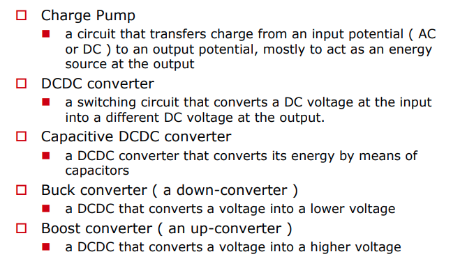
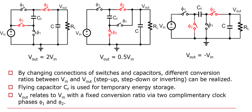
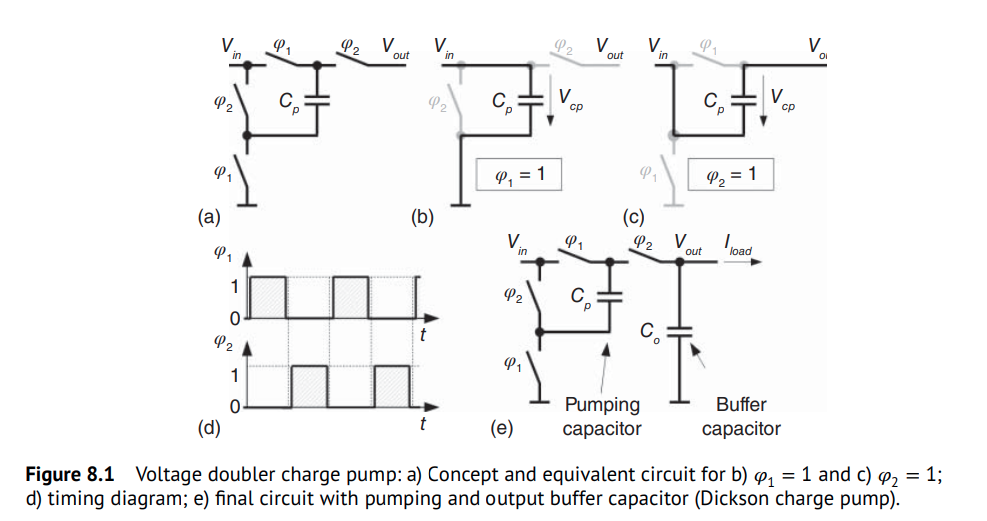
charge pumps are capacitive DC-DC converters. The two most common switched capacitor voltage converters are the voltage inverter and the voltage doubler circuit

voltage doubler

output buffer capacitor
To achieve a stable DC output voltage
Step-Wise Ramp-Up
\[ V_{in} C_p + V_{out,n-1}C_o = (V_{out,n}-V_{in})C_p + V_{out,n}C_o \]
We derive a recursive equation that describes the output voltage \(V_{out,n}\) after the \(n\)th clock cycle \[ V_{out,n} = \frac{2V_{in}C_p + V_{out,n-1}C_o}{C_p + C_o} \]
Voltage Ripple & Droop
\[\begin{align} (V_t - V_h)(C_p + C_o) &= \frac{I_{load}}{2f_{sw}} \\ (V_h - V_b)C_o &= \frac{I_{load}}{2f_{sw}} \end{align}\]
we obtain \[ V_t - V_b = \frac{I_{load}}{f_{sw}C_o}\left(1 - \frac{C_p}{2(C_p + C_o)}\right) \] That is, peak-to-peak ripple \[ \Delta V_{out,p2p} \approx \frac{I_{load}}{f_{sw}C_o} \space\space\space\space \text{if}\space\space C_o \gg C_p \]
Then, with aforementioned Step-Wise Ramp-Up equation, \(V_t = \frac{2V_{in}C_p + V_bC_o}{C_p + C_o}\) \[\begin{align} V_b &= 2V_{in} - \frac{I_{load}}{f_{sw}C_p}\left(1 + \frac{C_p}{2C_o}\right) \\ V_t &= 2V_{in} - \frac{I_{load}}{f_{sw}C_p}\left(1 - \frac{C_p}{2(C_p+C_o)}\right) \end{align}\]
Therefore, average output voltage \(\overline{V}_{out}\) in steady-state is \[ \overline{V}_{out} = \frac{V_t+V_b}{2}=2V_{in} - \frac{I_{load}}{f_{sw}C_p}\left(1 + \frac{C_p^2}{4C_o(C_p+C_o)}\right) \approx 2V_{in} - \frac{I_{load}}{f_{sw}C_p} \] which results in a simple expression for the output voltage droop
\[ \Delta V_{out} = \frac{I_{load}}{f_{sw}C_p} \]
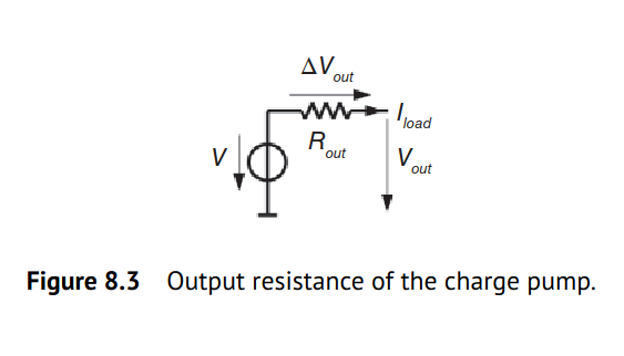
The charge pump can be modeled as a voltage source with a source resistance \(R_\text{out}\). Therefore, \(\Delta V_{out}\) can be seen as the voltage drop across \(R_\text{out}\) due to the load current:
\[
R_{out} = \frac{\Delta V_{out}}{I_{load}} = \frac{1}{f_{sw}C_p}
\] 
multiphase CP
\[ (V_t - V_b) (C_p + C_o) = I_{load}\Delta t \]
Therefore peak-to-peak ripple \[ \Delta V_{out,p2p} = \frac{I_{load}\Delta t}{C_p+C_o} = \frac{I_{load}\Delta t}{C_{tot}} \]
where \(C_{tot} = C_p+C_o\)
with \[ \left\{ \begin{array}{cl} V_b &= 2V_{in} - \frac{I_{load}\Delta t}{C_p} \\ V_t &= 2V_{in} - \frac{I_{load}\Delta t}{C_p} + \frac{I_{load}\Delta t}{C_p+C_o} \end{array} \right. \]
Then \[ \overline{V}_{out} = \frac{V_t+V_b}{2}=2V_{in} - \frac{I_{load}\Delta t}{C_p}\cdot \frac{C_p+2C_o}{2C_p+2C_o} \approx 2V_{in} - \frac{I_{load}\Delta t}{C_p} \] That is output voltage droop \[ \Delta V_{out} = \frac{I_{load}\Delta t}{C_p} \]
reference
Bernhard Wicht, "Design of Power Management Integrated Circuits". 2024 Wiley-IEEE Press
Breussegem, T. v., & Steyaert, M. (2013). CMOS integrated capacitive DC-DC converters. Springer
Zhang, Milin, Zhihua Wang, Jan van der Spiegel and Franco Maloberti. "Advanced Tutorial on Analog Circuit Design." (2023).
Anton Bakker, Tim Piessens., ISSCC2014 T9: Charge Pump and Capacitive DC-DC Converter Design
Wicht, B., ISSCC2020 T2: Analog Building Blocks of DC-DC Converters [https://www.nishanchettri.com/isscc-slides/2020%20ISSCC/TUTORIALS/T2Visuals.pdf]
Hoi Lee, ISSCC2018 T8: Fundamentals of Switched-Mode Power Converter Design [slides,transcript]