Link Modeling
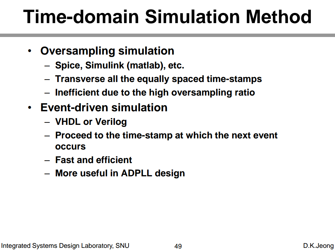
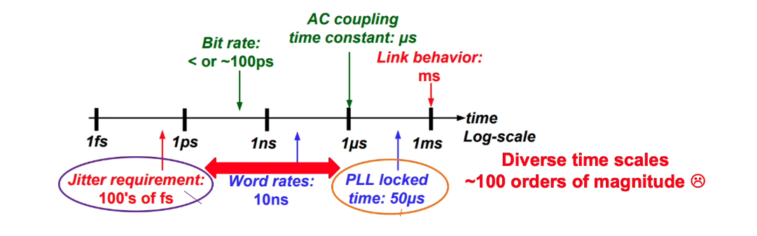
Time domain modeling
While many different analysis methods exist, including frequency and statistical analysis, time domain results remain the final sign-off
serdespy
Richard Barrie. serdespy — A python library for system-level SerDes modelling and simulation [https://github.com/richard259/serdespy]
JLSD
Kevin Zheng. JLSD — Julia SerDes [https://github.com/kevjzheng/JLSD]
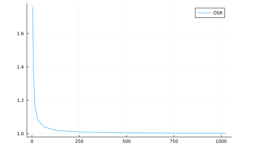
Kronecker product to create oversampled waveform
1 | function gen_wvfm(bits; tui, osr) |
normalized to the time step \[ \frac{\alpha}{s+\alpha} \overset{\mathcal{L}^{-1}}{\longrightarrow} \alpha\cdot e^{-\alpha t} \]
The integral of impulse response of low pass RC filter \(\int_{0}^{+\infty} \alpha\cdot e^{-\alpha t}dt =
1\) — sum(ir*dt)
1 | function gen_ir_rc(dt,bw,t_len) |
1 | using Plots |
Elastic Buffer
the elastic buffer approach would be the most general for modeling say frequency offsets between TX and RX (will be addressed in future development)

generate PAM symbols
here Big Endian
1 | #generate PAM symbols |
1 | function int2bits(num, nbit) |
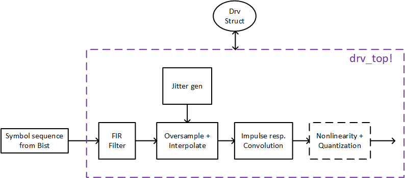
Detailed Transmitter
DaVE
DaVE — tools regarding on analog modeling, validation, and generation, [https://github.com/StanfordVLSI/DaVE]
Statistical Eye
Sanders, Anthony, Michael Resso and John D'Ambrosia. “Channel Compliance Testing Utilizing Novel Statistical Eye Methodology.” (2004).
X. Chu, W. Guo, J. Wang, F. Wu, Y. Luo and Y. Li, "Fast and Accurate Estimation of Statistical Eye Diagram for Nonlinear High-Speed Links," in IEEE Transactions on Very Large Scale Integration (VLSI) Systems, vol. 29, no. 7, pp. 1370-1378, July 2021, doi: 10.1109/TVLSI.2021.3082208.
HSPICE® User Guide: Signal Integrity Modeling and Analysis, Version Q-2020.03, March 2020
IA Title: Common Electrical I/O (CEI) - Electrical and Jitter Interoperability agreements for 6G+ bps, 11G+ bps, 25G+ bps I/O and 56G+ bps IA # OIF-CEI-04.0 December 29, 2017 [pdf]
J. Park and D. Kim, "Statistical Eye Diagrams for High-Speed Interconnects of Packages: A Review," in IEEE Access, vol. 12, pp. 22880-22891, 2024 [pdf]
StatOpt
Savo Bajic, ECE1392, Integrated Circuits for Digital Communications: StatOpt in Python [https://savobajic.ca/projects/academic/statopt] [https://www.eecg.utoronto.ca/~ali/statopt/main.html]
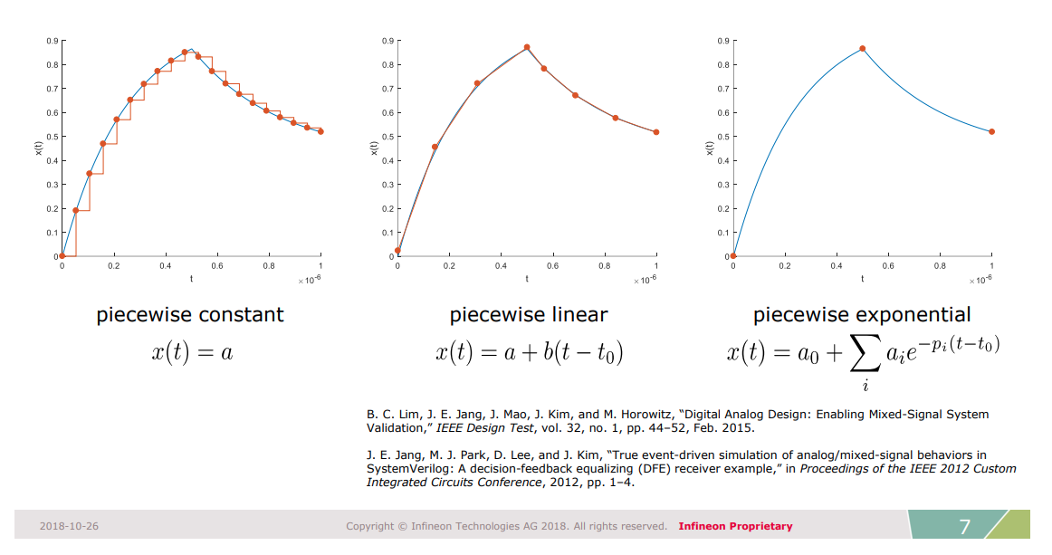
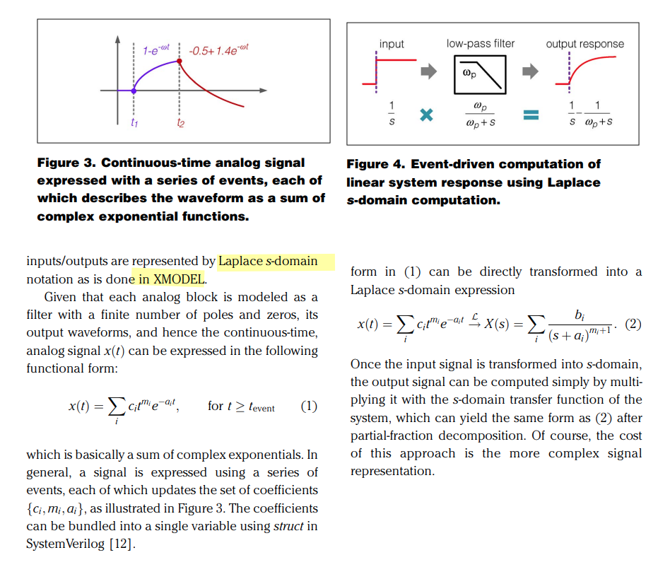
Analog Signals Representation
Ben Yochret Sabrine, 2020, "BEHAVIORAL MODELING WITH SYSTEMVERILOG FOR MIXED-SIGNAL VALIDATION" [https://di.uqo.ca/id/eprint/1224/1/Ben-Yochret_Sabrine_2020_memoire.pdf]
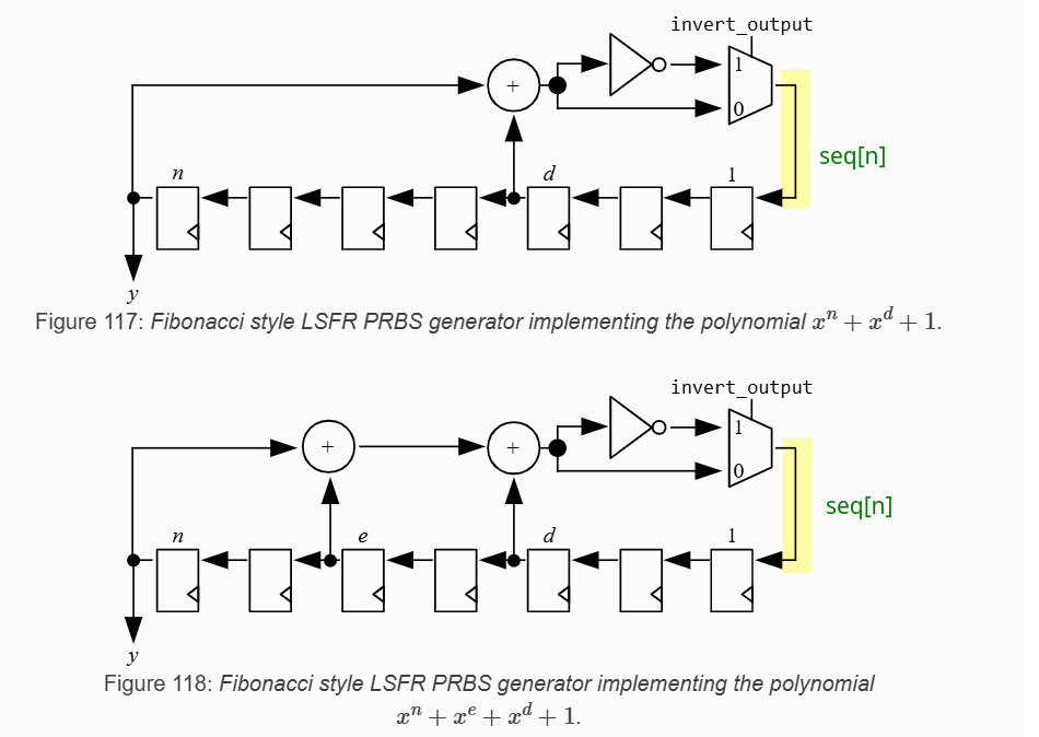
PRBS Generator & Checker
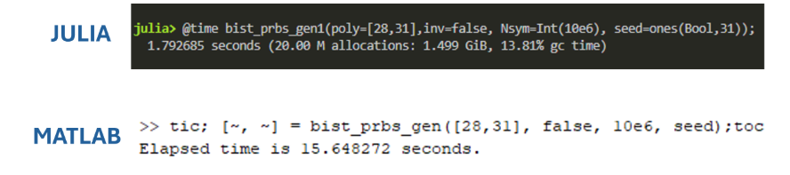
PRBS Generator
1 | # Julia |
1 | %% Matlab |
[https://github.com/kevjzheng/JLSD/blob/main/Pluto%20Notebooks/pdf/JLSD_pt1_background.pdf]
PRBS Checker
previous bit determine current bit

1 | function ber_check_prbs(rcvd_bits; poly, inv, seed, lock_status, lock_cnt, lock_threshold, ber_err_cnt, ber_tot_cnt) |
Reference
MATLAB® and Simulink® RF and Mixed Signal [https://www.mathworks.com/help/overview/rf-and-mixed-signal.html]
Lim, Byong Chan, M. Horowitz, "Error Control and Limit Cycle Elimination in Event-Driven Piecewise Linear Analog Functional Models," in IEEE Transactions on Circuits and Systems I: Regular Papers, vol. 63, no. 1, pp. 23-33, Jan. 2016 [https://sci-hub.se/10.1109/TCSI.2015.2512699]
—, Ph.D. Dissertation 2012. "Model validation of mixed-signal systems" [https://stacks.stanford.edu/file/druid:xq068rv3398/bclim-thesis-submission-augmented.pdf]
—, J. -E. Jang, J. Mao, J. Kim and M. Horowitz, "Digital Analog Design: Enabling Mixed-Signal System Validation," in IEEE Design & Test, vol. 32, no. 1, pp. 44-52, Feb. 2015 [http://iot.stanford.edu/pubs/lim-mixed-design15.pdf]
— , Mao, James & Horowitz, Mark & Jang, Ji-Eun & Kim, Jaeha. (2015). Digital Analog Design: Enabling Mixed-Signal System Validation. Design & Test, IEEE. 32. 44-52. [https://iot.stanford.edu/pubs/lim-mixed-design15.pdf]
S. Liao and M. Horowitz, "A Verilog piecewise-linear analog behavior model for mixed-signal validation," Proceedings of the IEEE 2013 Custom Integrated Circuits Conference, San Jose, CA, USA, 2013 [https://sci-hub.se/10.1109/CICC.2013.6658461]
—, M. Horowitz, "A Verilog Piecewise-Linear Analog Behavior Model for Mixed-Signal Validation," in IEEE Transactions on Circuits and Systems I: Regular Papers, vol. 61, no. 8, pp. 2229-2235, Aug. 2014 [https://sci-hub.se/10.1109/TCSI.2014.2332265]
—,Ph.D. Dissertation 2012. Verilog Piecewise Linear Behavioral Modeling For Mixed-Signal Validation [https://stacks.stanford.edu/file/druid:pb381vh2919/Thesis_submission-augmented.pdf]
Ji-Eun Jang et al. “True event-driven simulation of analog/mixed-signal behaviors in SystemVerilog: A decision-feedback equalizing (DFE) receiver example”. In: Proceedings of the IEEE 2012 Custom Integrated Circuits Conference. 2012 [https://sci-hub.se/10.1109/CICC.2012.6330558]
—, Si-Jung Yang, and Jaeha Kim. “Event-driven simulation of Volterra series models in SystemVerilog”. In: Proceedings of the IEEE 2013 Custom Integrated Circuits Conference. 2013 [https://sci-hub.se/10.1109/CICC.2013.6658460]
—, Ph.D. Dissertation 2015. Event-Driven Simulation Methodology for Analog/Mixed-Signal Systems [file:///home/anon/Downloads/000000028723.pdf]
"Creating Analog Behavioral Models VERILOG-AMS ANALOG MODELING" [https://www.eecis.udel.edu/~vsaxena/courses/ece614/Handouts/CDN_Creating_Analog_Behavioral_Models.pdf]
Rainer Findenig, Infineon Technologies. "Behavioral Modeling for SoC Simulation Bridging Analog and Firmware Demands" [https://www.coseda-tech.com/files/Files/Dokumente/Behavioral_Modeling_for_SoC_Simulation_COSEDA_UGM_2018.pdf]
CC Chen. Why Efficient SPICE Simulation Techniques for BB CDR Verification? [https://youtu.be/Z54MV9nuGUI]
T. Wen and T. Kwasniewski, "Phase Noise Simulation and Modeling of ADPLL by SystemVerilog," 2008 IEEE International Behavioral Modeling and Simulation Workshop, San Jose, CA, USA, 2008 [slides, paper]
Jaeha Kim,Scientific Analog. UCIe PHY Modeling and Simulation with XMODEL [pdf]
S. Katare, "Novel Framework for Modelling High Speed Interface Using Python for Architecture Evaluation," 2020 IEEE REGION 10 CONFERENCE (TENCON), Osaka, Japan, 2020 [https://sci-hub.se/10.1109/TENCON50793.2020.9293846]