Data Converter in Action
Sigma-Delta DAC
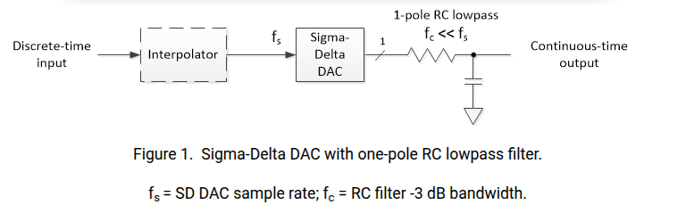
Sigma-delta digital-to-analog converters (SD DAC’s) are often used for discrete-time signals with sample rate much higher than their bandwidth
- Because of the high sample rate relative to signal bandwidth, a very simple DAC reconstruction filter (Analog lowpass filter) suffices, often just a one-pole RC lowpass
1 | R= 4.7e3; % ohms resistor value |
Appendix
1 | % https://www.dsprelated.com/showarticle/1642.php |
DAC ZOH
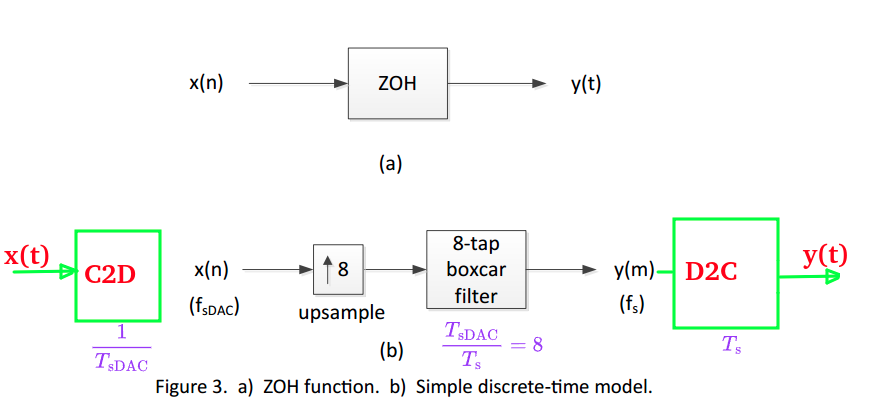
The last D2C is in human vision, which connect discrete time \(y(m)\) with line, implicitly
Noise-Shaping SAR ADCs
TODO 📅
reference
Dan Boschen. sigma delta modulator for DAC [https://dsp.stackexchange.com/a/88357/59253]
Neil Robertson, Model a Sigma-Delta DAC Plus RC Filter [https://www.dsprelated.com/showarticle/1642.php]
—, Modeling a Continuous-Time System with Matlab [https://www.dsprelated.com/showarticle/1055.php]
—, Modeling Anti-Alias Filters [https://www.dsprelated.com/showarticle/1418.php]
—, DAC Zero-Order Hold Models [https://www.dsprelated.com/showarticle/1627.php]
—, “A Simplified Matlab Function for Power Spectral Density”, DSPRelated.com, March, 2020, [https://www.dsprelated.com/showarticle/1333.php]
Jason Sachs. Return of the Delta-Sigma Modulators, Part 1: Modulation [https://www.dsprelated.com/showarticle/1517/return-of-the-delta-sigma-modulators-part-1-modulation]
Woogeun Rhee. ISCAS 2019 Mini Tutorials: Single-Bit Delta-Sigma Modulation Techniques for Robust Wireless Systems [https://youtu.be/OEyTM4-_OyA?si=vllJ5Pe8I3lqb_Vl]
Venkatesh Srinivasan, ISSCC 2019 T5: Noise Shaping in Data Converters
Nan Sun,IEEE CAS 2020: Break the kT/C Noise Limit [https://www.facebook.com/ieeecas/videos/break-the-ktc-noise-limit/322899188976197/]
Yun-Shiang Shu, ISSCC 2022 T3: Noise-Shaping SAR ADCs
Xiyuan Tang, CICC 2025 ES2-1: Noise-Shaping SAR ADCs - From Fundamentals to Recent Advances