SystemVerilog clocking block
Assignment at <interface>.<clocking block>.<output signal> (i.e. synchronous) do NOT change <interface>.<output signal> until active clock edge.
1 | // router_io.sv |
All interface signals are asynchronous and without a direction spection (i.e. input, output, inout).
- The direction can only be specified in
clockingblock for synchronous signals- or a
modportfor asynchronous signalsAll directions for the signals in the clocking block must be with respect to the test program;
1 | // test.sv |
1 | // router_test_top.sv |
compile:
1 | $ vcs -sverilog -full64 -kdb -debug_access+all router_test_top.sv test.sv router_io |
file with `
timescalemust be placed in the first, which isrouter_test_top.svin above example
clocking.output
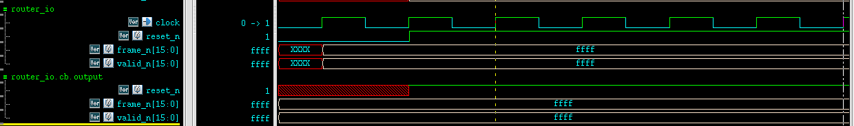
systemverilog don't pass clocking.output to interface's until current or next active edge and after output-skew
clocking.input
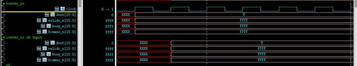
Systemverilog automatically update clocking.input signal from interface's value, input-skew before active edge
Gotcha
An interface must be compiled separately like a
module and CANNOT `include inside a
package or ohter module
Innovus check mode variants
checkDesign
check_timing
checkPlace
setDesignMode
setFPlanMode
setEcoMode
setPlaceMode
setRouteMode
setExtractRCMode
setOptMode
Innovus Fix DRC Violation
1 | clearDrc |
Innovus Path Based Analysis
aocv : Re-timing the timing critical paths using the LOCV deratingfactors
path_slew_propagation : Re-timing the timing critical paths using the actual slews for thepath
aocv_path_slew_propagation : Combination of re-timing with aocv + path_slew_propagation
waveform_propagation : Re-timing with waveform effect taken into consideration during delayCal
questasim sim flow
1 | vlib work |
-voptargs=+acc: Add the option-voptargs=+accto the vsim command, This enables full visibility into every aspect of the design.
1 | module topmodule; |
uvm:
1 | > vlog test_pkg.sv tb_top.sv -L $QUESTA_HOME/uvm-1.2 |
reference:
A Short Intro to ModelSim Verilog Simulator URL: https://users.ece.cmu.edu/~jhoe/doku/doku.php?id=a_short_intro_to_modelsim_verilog_simulator
devops
Restart Xfce panel
1 | xfce4-panel -r |
Rocky Linux 8 rpm for cadence binary and cdnshelp
qt5 and openssl
1 | sudo yum install openssl compat-openssl10 qca-qt5-ossl.x86_64 openssl-devel |
library preparation for EDA installation
1 | libc6, gdb |
Rocky Linux 8 extend LVM in VMware
1 | 1) gparted extend |
compile vim from source with GUI support
1 | # gtk3 in Rocky Linux 8.5 |
binkey
Inserting a new line below: o
above: O
To insert before the cursor: i
After: a
Before the line (home): I
Append at the end of line: A
network connection using nmcli
Problem
There is no network connection and device is not managed
1 | $ nmcli device status |

solution
1 | sudo nmcli networking on |
Then, eth0 is connected
1 | $ nmcli device status |

What is the proper method to remove old kernels from a Red Hat Enterprise Linux system?
Red Hat Enterprise Linux 8
The YUM version 4 (based on the upstream DNF project)
method for removing kernels and keeping only the latest version and
running kernel:
1 | $ yum remove --oldinstallonly |
From the yum man page:
1 | dnf [options] remove --oldinstallonly |
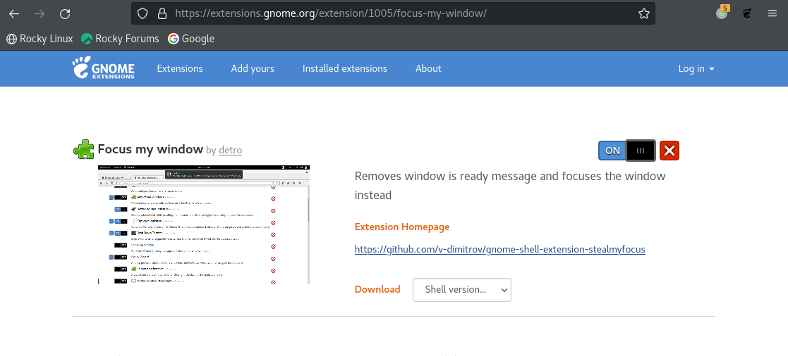
New windows and forms appear behind the Library Manager in background when using GNOME 3
Using Red Hat Enterprise Linux 8, Rocky Linux 8 and the GNOME 3 window manager, the new Virtuoso Schematic/Layout/ADE windows and forms sometimes pop up under or below the Library Manager or on the desktop in the background instead of the foreground and cannot be seen. Sometimes, they are iconized; they do not come on the top in front, though it is the most recent window opened.
solution
Install Focus my window GNOME Shell extension
reference
Article (11612426) Title: New windows and forms appear behind the Library Manager in background or iconized instead of foreground on RHEL and SuSE Linux in GNOME, KDE Desktop, Metacity window manager URL: https://support.cadence.com/apex/ArticleAttachmentPortal?id=a1Od0000000nSXCEA2
VMware Disk Shrink
In Guest OS and run
1 | sudo vmware-toolbox-cmd disk shrink / |
https://superuser.com/q/211798
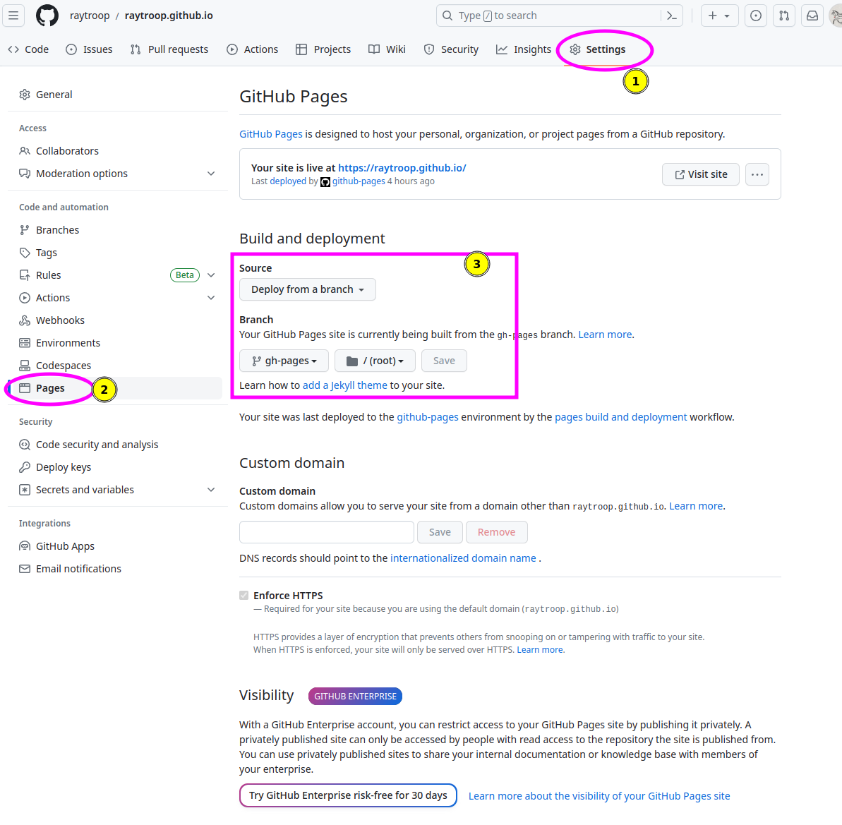
GitHub Pages Build and deployment
The repository visibility shall be public
How to squash all git commits into one?
https://stackoverflow.com/a/9254257/8037585
As of git
1.6.2, you can use git rebase --root -i
For each commit except the first, change pick to
squash.
this works find, but I had to do a forced push. be careful!
git push -f
Build VMware host modules
1 | git clone git@github.com:mkubecek/vmware-host-modules.git |
AWT-EventQueue-0 Matlab
1 | Renaming libstdc++.so.6 to libstdc++.so.6old solved it for me in MATLAB 2021B UBUNTU 20.04. Thanks! |
[https://www.mathworks.com/matlabcentral/answers/329796-issue-with-libstdc-so-6#comment_2316900]
All is well
爱
自信,自爱
真诚,善良
勇敢,坚定
热爱生活
1 | 成熟的爱情,就是在保留自己完整性和独立性的条件下,也就是保持自己个性的条件下与他人合二为一。 |
1 | 愛是一種活動,不是被動的感情,是給予。 |
1 | 愛是一種每天的實踐, |
1 | 当你喜欢你自己的时候,你才会由内而外散发出一种自信,散发出一种自由。 |
1 | 爱,是为了促进自己和他人心智成熟,而不断拓展自我界限,实现自我完善的一种意愿。 |
1 | 爱是常觉亏欠,是不求回报的付出,是想触碰又缩回的手。 |
1 | 1. 吸引对方的永远是你自信而产生的人格魅力,而不是你对TA好。 |
1 | 过于自卑的人不适合谈恋爱,为什么呢? |
1 | 学会接纳自己,满足自己,爱自己。 |
1 | 缺爱,本质上缺的是安全感和自我认同。 |
1 | 多数情况下,缺爱者并不是在爱别人,而是在享受被爱的过程。 |
1 | 可以这么说,缺爱的人,并不是得不到真正的爱,是ta识别不出什么是真正的爱。 |
1 | 他童年缺爱,到成年了反而对爱过度渴求,他所做的一切努力,都是希望别人说他好,对他好, |
1 | 我老公就是,非常敏感,没安全感,有时会喝多,然后就狂打电话,反复说“老婆,你要在家等我”这类的话, |
1 | 爱是一种能力,需要从自我理解开始。一个人如果内心空虚、缺乏自爱,就难以给予他人健康、平衡的爱,因为他们可能混淆了牺牲与爱, |
1 | 回到问题,我现在的想法是,不爱自己的人,自己本身就处于匮乏的状态,自己都没有满足,是不能给予别人什么东西的, |
1 | 因为爱自己,爱才能溢出来爱别人 对自己好才知道如何对别人好,不然投射出来的都是自己的欲望和需求。很多人爱别人是因为需要别人,是对别人有欲望,而不是爱溢出来的。 |
1 | 以前我对自己的爱,一直是有条件的,也一直处于自我厌恶的状态,根本做不到自我认同, |
1 | 没有动力最核心的原因是,你非但不爱自己,你甚至是厌恶自己的。 |
1 | 从小缺爱的孩子,最难的不是如何去爱别人,而是不会爱自己。 |
1 | 缺爱的人不是病人,也不是弱者,甚至很多缺爱的人因为无法依靠别人,而在工作、学习领域,有更加出色的表现——ta们只是在感情中比别人起步更晚。 |
1 | 童年时得到父母持续关爱的孩子,成年后往往非常有安全感,并且坚信自己是值得爱的,是有价值的。他们相信只要坚持真实的自己,就能够得到别人的爱。 |
1 | 缺爱缺的不只是爱,还有安全感,自信,自爱,配得感… |
1 | 恋爱可以逼有原生家庭缺陷的人,重新认识自己。 |
1 | 亲密关系最能短时间的发掘一个人的内在品质,包括性格、人品、处事方式、心理素质。 |
1 | 只有自卑的人才会。 |
1 | 容易想太多的人,其实是缺乏安全感 |
1 | 阻碍孩子成长的,往往不是贫穷,也不是忙碌,而是家庭中的内耗。 |
1 | 这就是父母常有的一种病态的亲子绑定思维——“他的表现,关乎我的脸面”。 |
1 | 养育孩子,表面上看起来是教育,其实还有一件更重要的事,那就是: |
1 | 缺爱的人,不愿意展现真实的自己,因为觉得自己的感受并不是都能被接受的。 |
1 | 记得曾经看到过一句话:父母骂孩子,孩子不会停止爱父母,却会停止爱自己。 |
1 | 凤仪: |
1 | 不会。 |
1 | 松花酿酒: |
1 | 《不原谅也没关系》[美]皮特·沃克 |
[Why Unloved People Hate Themselves]
[How Unloving Parents Generate Self-Hating Children]
阅读
不原谅也没关系 - 皮特·沃克
爱的艺术 - 弗洛姆
悉达多 - 赫尔曼·黑塞
启发
1 | 再谈从极端的讨好反应中康复: |
1 | 体会了后悔和遗憾,才会明白,人生的出场顺序有多重要。 |
1 | 没有自我,才需要渡情劫,然后让你认识自我,开始觉醒完善自我。 |
1 | 长大会变成无法去接纳不完美的自己的人 |
1 | 越是遇到那个让你心动的人,心动感越强,你就越是容易失去对方。 |
1 | 你提供不了充足的物质和社会资源我不怪你,但是提供一个稳定和谐的家庭环境,是为人父母的责任之一。 |
1 | 一个人如果不懂得对自己好,不懂得爱自己,通过看见和满足自己的需求、欲望和感受为一切评价的前提,那么很容易就流回到外界评价体系里活成他人期待的样子了。 |
1 | - 对他人的愧疚。或许儿时常有父母或重要他人跟你诉苦,说自己多么舍不得吃舍不得穿舍不得花钱,而且是为了你。 |
1 | 小金: |
1 | 不是。 |
1 | 另外,當一樁不幸的婚姻面臨解體時,孩子也會成為被投射的對象。在這種情況下,父母會陳腐地認定他們不能離婚,理由是離婚會剝奪孩子可以從一個完整家庭得到的幸福。 |
1 | 一个人但凡和原生家庭深度纠缠,过度在意成绩会不会被爸妈认可,做出的选择能不能被爸妈支持,以及自己能不能得到爸妈的爱。 |
1 | 所以,为人父母,衡量自己给孩子的爱是否足够和适合,要看你的孩子是不是想哭就哭,想笑就笑,不刻意取悦和讨好,自信且敢于表达自我 |
1 | 远离LJ: |
1 | 只有听话的乖孩子,才能得到家长认同和夸奖。 |
1 | 为什么小时候越乖巧的人,长大越容易有心理问题呢?是因为,如果说人的一生是有任务的话,那他的任务就是成为他自己。 |
1 | 他们习惯伪装自己,让自己“看上去很好”,而在伪装的背后,承受的是更大的痛苦。 |
1 | 这个故事没有讲任何大道理,也没试图列举一系列所谓「优点」来抵消自卑,而只是呈现和描述了事实: |
1 | 香菜也行: |
1 | 1. 自我认知不足,无法敞开心扉,坦荡真诚 |
1 | 因为你不够「成熟」。具体表现有四种:缺乏安全感、以自我为中心、自卑、控制欲强。 |
1 | 爱本身,就是每一个孩子值得一生去学习,去追求,去实践,去成长的课题。 |
1 | 一个缺爱的孩子,在认知局限的基础上,他不会认为这是父母的原因,他会把问题归咎于自己。一定是我不够好,一定是我不够可爱,所以父母不爱我。 |
1 | 愤怒是我们的思维方式造成的。 它的核心是尚未满足的需要。 |
1 | 『最终,家庭对孩子的影响力是最关键的:家庭不仅创造了孩子所在的世界,还告诉孩子这个世界应该怎样被诠释。』 |
1 | 钱和知识我在成长的路上都可以得到,而在充满爱的家庭里长大的孩子,他们身上那种强大的自信和安全感是我这辈子都模仿不来的。 |
1 | 早熟的人,成熟晚。 |
1 | 社会化程度低。 |
1 | 很简单,因为原生家庭赋予了你“孩子”的角色。 |
1 | 他们的特点就是聪明勤奋、质朴内向、自律克己、自负和自卑掺半(唯独就是不自信)。 |
1 | 做题家在最需要社会关系的时候严重缺失,长大了人际交往方面不出问题是不正常的 |
1 | 原生家庭的差,其实物质只是最不起眼的部分,真正伤人的是家暴,精神暴力。 - 凡人 |
1 | 因为你从小不被父母允许表达愤怒,导致了习得性无助。 |
1 | 当然父母通常并没有恶毒到故意训练你, |
1 | 不喜欢与人发生冲突的老实人,内心都住着一个没有父母撑腰的“内在小孩”。所谓的情绪稳定,并不一定是没有脾气,而是他们缺乏面对冲突的能力,所以看起来是个好脾气。 |
1 | 在这种低自尊家庭长大的孩子,也容易从小耳濡目染父母的行为,而习得跟父母同样的行为模式, |
1 | 人的地位和尊严是由自己决定的,别人对你的尊重和欣赏,来源于你自身实力构成的魅力,而不是逃避现实和害怕冲突的闪躲。 |
1 | 激发内疚感在某些情况下可能暂时有效,让孩子符合家长和社会的规范和期待,变成“别人家的好孩子”,受众人羡慕和称赞。 |
1 | 快乐与“不配得”捆绑(自我价值的条件化): |
1 | 青枣: |
1 | 父母从孩子出生就阻碍了他的正常心理发展。 |
1 | 原生家庭能逼你不敢和别人介绍自己的家庭,丢人。 |
1 | 在网上刷到这样一段话, |
1 | 根源就是缺爱。 |
1 | 其实,一个家庭贫穷的本质,就是家里面有一个制造内耗的人。 |
1 | 告诉你一个秘密:一个家庭最可怕的不是穷,而是有一个经常制造内耗的人,不停地制造矛盾和争吵。 |
1 | 根源是人自身的矛盾。但人不是天然要矛盾的。 |
1 | 你要追求的不是死磕能力,更重要的是胆气、是洒脱,是外物为我所用而不纠结的心态。 |
1 | 如果原生家庭没有帮你把内心基础框架打好,你最少花20年重建自己的内心世界。 |
1 | 一个男生的魅力,除了对异性的尊重、对品性的追求,更体现为一种坦荡与责任感。 |
1 | 说一点感想吧,男人魅力很大程度上来自于自信和坦诚,真的很少有人做得到位。 |
1 | 他的周身充满着负能量,幸福感低下,没有共情能力,不会爱自己,也不会爱别人,这样的人,你让他怎么爱伴侣,怎么爱孩子? |
1 | 爱是一种能力,这种能力是溢出的,甚至是转移的,爱有来源,才有去处。 |
1 | 因为原生家庭糟糕的人很难真正对感情做出正向的回馈。 |
1 | 这种处处为难自己的路数,对于小孩子来说,我不能说它没有意义。 |
1 | “只有我完美了,对方才会喜欢我”,这种想法是“我执”的一种,是隐藏较深的自我中心论。错在只关注自己的能力和意愿,却不关注对方的需求和感受。 |
1 | 穷人家的孩子往往缺乏安全感,惶惶不可终日,担心焦虑占据了他们很多的精力和时间,间接让他们没法专注思考和 |
1 | 这世界上没有捷径,任何所谓的弯路都是必经之路。 |
1 | 缺少一个概念:我要。 |
1 | 最可怕的是第五点——亲密关系中的自卑感。 |
1 | 骇客辉 2022-04-29 18:52:14 |
1 | 未经审视的成年人格是由童年创伤引起的态度、行为和心理反射的集合,其主要目的是应对关于童年的机体 |
1 | 我发现,我激励自己的方式无意中促成了自我憎恨。由于认为自己'应该’做到许多事情, |
1 | All our life, we are about to get rid of the expectations of others to find the true self. |
1 | 别人眼中的你,不是真的你。你眼中的自己,也不是真的你。你眼中的别人,才是真正的你 |
1 | 一、 健康与安全 |
1 | 病态自卑者难以停止内心挣扎的原因有两点:一是难以放弃对理想化自我的追求;二是无法接受真实的自己。 |
1 | 什么是爱情? 心理学家弗洛姆对爱是这样定义的: 真正的爱是内在创造力的表现, 包括关怀、 尊重、 责任和了解等诸多因素。 |
1 | Until you make the unconscious conscious, it will direct your life and you will call it fate. |
1 | Accept reality as it is and to try not to regret the past and try to improve the situation. |
1 | The two most important days in your life are the day you are born and the day you find out why. |
1 | We have to dare to be ourselves, however frightening or strange that self may prove to be. |
1 | Fear can hold you prisoner. Hope can set you free |
1 | May Your Choices Reflect Your Hopes, Not Your Fears |
1 | We have to dare to be ourselves, however frightening or strange that self may prove to be. |
1 | 人生不能像做菜,把所有的料都準備好了才下鍋。 |
1 | 法律学者罗翔曾说:原生家庭不好的人,慢半拍、慢几拍已经很优秀了。别责怪自己,因为在别人成长的时候,你还陷在原生家庭的内耗里。在别人搞事业的时候,你还在搞自己。 |
1 | 对于可控的事情要保持谨慎,对于不可控的事情要保持乐观。 |
1 | 事实上,你们对我的百般注解和识读,并不构成万分之一的我,却是一览无遗的你们 |
1 | 不要因爲一時的情緒而做出永久的決定 |
1 | 最後記住導航裡的那句話:前方道路擁堵,但您仍在最優路線上 |
1 | 瑞士著名心理学家卡尔·荣格说过:“人们会想尽办法,各种荒谬的办法,来避免面对自己的灵魂。 |
1 | Self-pity gets pretty close to paranoia and paranoia is one of the very hardest things to reverse. |
1 | Envy is a really stupid sin because it's the only one you could never possibly have any fun at. There's a lot of pain and no fun. |
1 | Every mischance in life was an opportunity to learn something and your duty was not to be submerged in self-pity, |
1 | 卡森给的确保痛苦生活的处方包括: |
1 | The past was a lie, that memory has no return, that every spring gone by could never be recovered, |
1 | Life can only be understood backwards; but it must be lived forwards. |
1 | 我有一种哲学,就是不为过去所做的事情后悔。只是设法记住你当时为什么做出那样的决定。 |
1 | The healthier strategy for controlling the fear of failure is to redefine the meaning of your mistakes. |
1 | 一、来做什么? |
【圆桌派 第三季】EP24 | 失恋: 失恋是一种病
1 | 我永远不能把我的快乐寄托在另一个人的合作上 |
1 | 每当有人问起,为什么我不恋爱的时候,我都以麻烦为由搪塞过去。 |
【圆桌派 第四季】EP27 | 分手:拒绝的理由
1 | 成熟的人,处事不会用人情来胁迫人家。预留人家say no 的权利,也是對别人的尊重。 |
【圆桌派 第六季】 EP8 挑战:“兴致勃勃地去失败”
1 | 爱是无条件的,怎么爱是有方法的。 |