Loop Inductance & Partial Inductance
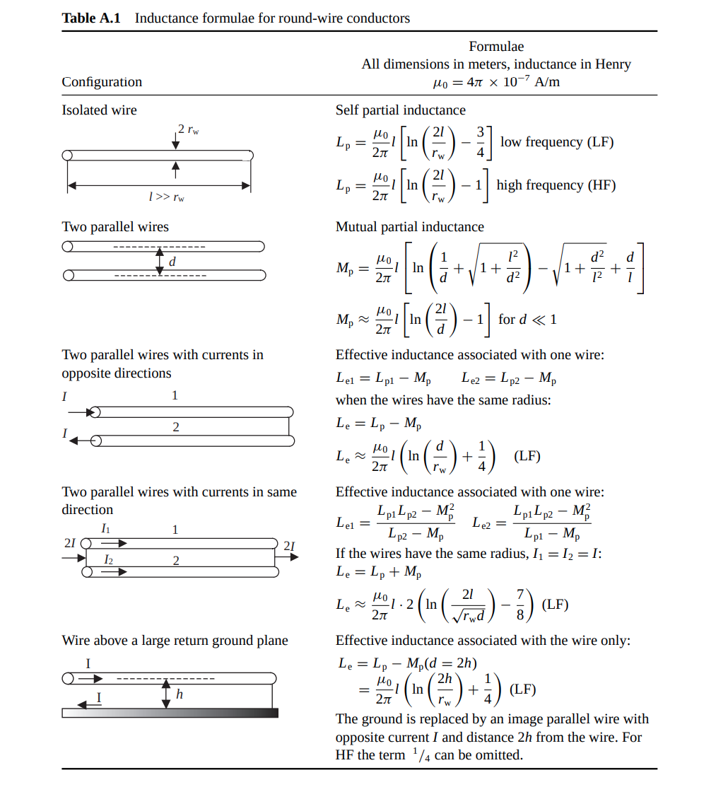
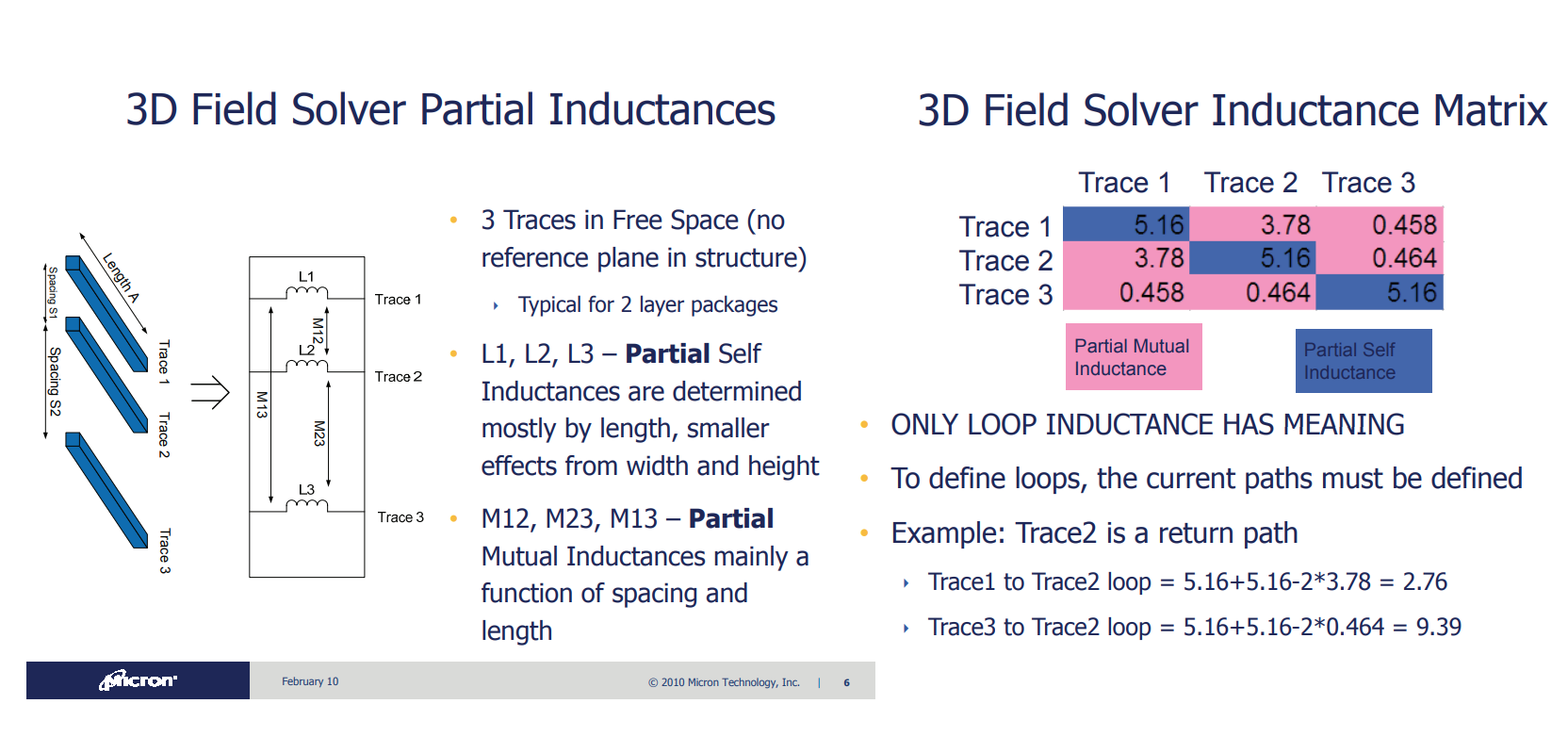
| currents in OPPOSITE direction | currents in SAME direction | |
|---|---|---|
| self partial inductance | + | |
| mutual partial inductance | - | + |
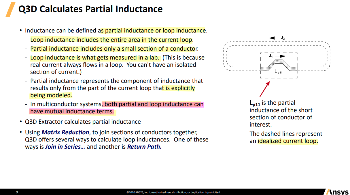

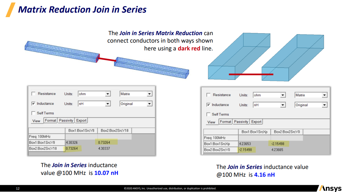
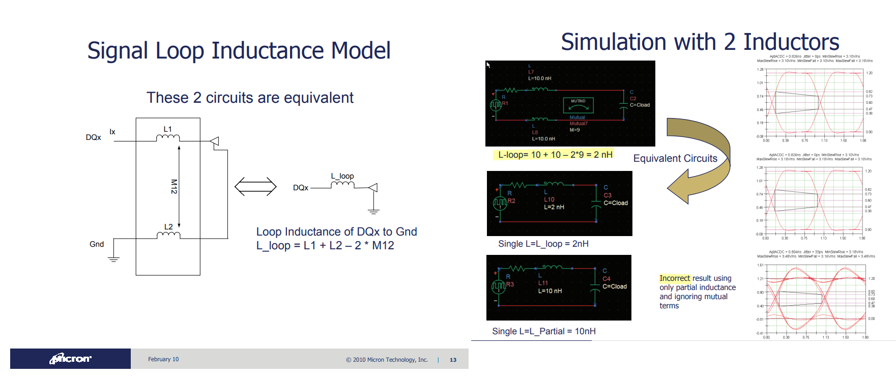
loop inductance
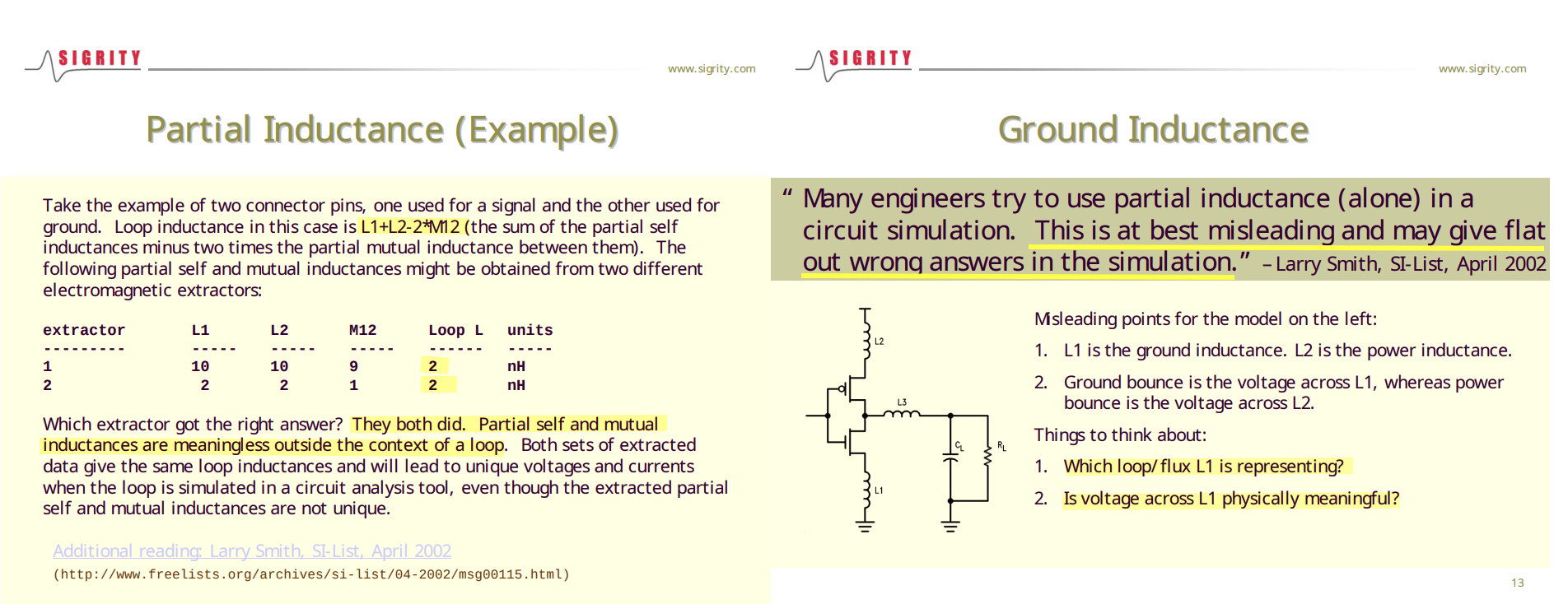
由法拉第定律所導出的total loop inductance是迴路整體的效應,沒辦法區分出電源與地路徑上各別的電感,即難以分析 電感對power bounce或ground bounce分別的影響,所以有了partial inductance的定義
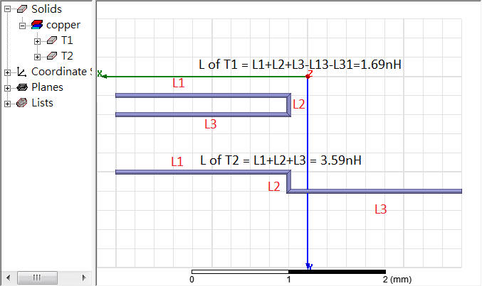
partial inductance
The first problem with using loop inductance to model the conductors of a loop is that at different frequencies, the return path
reference
Paul, Clayton R. Inductance: Loop and Partial. Hoboken, N.J. : [Piscataway, N.J.]: Wiley ; IEEE, 2010.
Spartaco Caniggia. Signal Integrity and Radiated Emission of High‐Speed Digital Systems. Wiley 2008
Clayton R. Paul, Partial Inductance [https://ewh.ieee.org/soc/emcs/acstrial/newsletters/summer10/PP_PartialInductance.pdf]
Yuriy Shlepnev. How Interconnects Work: Characteristic Impedance and Reflections [https://www.linkedin.com/pulse/how-interconnects-work-characteristic-impedance-yuriy-shlepnev/]
-. How Interconnects Work: Bandwidth for Modeling and Measurements [https://www.linkedin.com/pulse/how-interconnects-work-bandwidth-modeling-yuriy-shlepnev/?trackingId=874kpm3XuNyV9D0eP6IioA%3D%3D]
Eric Bogatin. Pop Quiz: When is an Interconnect Not a Transmission Line? [https://www.signalintegrityjournal.com/blogs/4-eric-bogatin-signal-integrity-journal-technical-editor/post/265-pop-quiz-when-is-an-interconnect-not-a-transmission-line]
TeledyneLeCroy/SignalIntegrity Python tools for signal integrity applications [SignalIntegrityApp]
A Look at Transmission-Line Losses [http://blog.teledynelecroy.com/2018/06/a-look-at-transmission-line-losses.html]
How Much Transmission-Line Loss is Too Much? [http://blog.teledynelecroy.com/2018/06/how-much-transmission-line-loss-is-too.html]
Y. Massoud and Y. Ismail, "Gasping the impact of on-chip inductance," in IEEE Circuits and Devices Magazine, vol. 17, no. 4, pp. 14-21, July 2001
Randy Wolff. Signal Loop Inductance in [Pin] and [Package Model] [https://ibis.org/summits/feb10/wolff.pdf]
Raymond Y. Chen, Raymond Y. Chen. Fundamentals of S Fundamentals of S-Parameter Parameter Modeling for Power Distribution Modeling for Power Distribution System (PDS) and SSO Analysis System (PDS) and SSO Analysis [https://ibis.org/summits/jun05/chen.pdf]
ANSYS Q3D Getting Started LE05. Module 5: Q3D Inductance Matrix Reduction [https://innovationspace.ansys.com/courses/wp-content/uploads/sites/5/2021/07/Q3D_GS_2020R1_EN_LE05_Ind_Matrix.pdf]