Oscillator Phase Noise
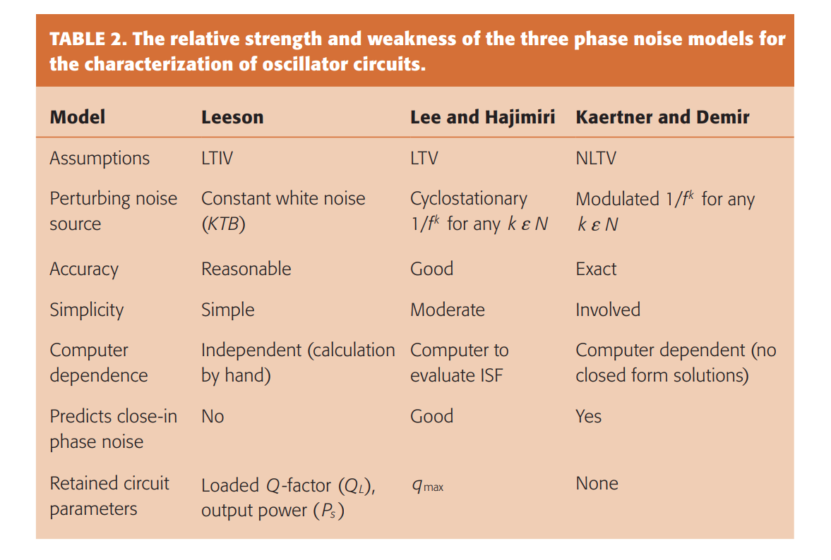
Poddar, Ajay & Rohde, Ulrich & Apte, Anisha. (2013). How Low Can They Go?: Oscillator Phase Noise Model, Theoretical, Experimental Validation, and Phase Noise Measurements. Microwave Magazine, IEEE. [http://time.kinali.ch/rohde/noise/how_low_can_they_go-2013-poddar_rohde_apte.pdf]
F. L. Traversa, M. Bonnin and F. Bonani, "The Complex World of Oscillator Noise: Modern Approaches to Oscillator (Phase and Amplitude) Noise Analysis," in IEEE Microwave Magazine, vol. 22, no. 7, pp. 24-32, July 2021 [https://sci-hub.ru/10.1109/MMM.2021.3069535]
Phase Noise Definition
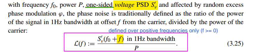
Eq. (3.25) is widely adopted by industry and academia
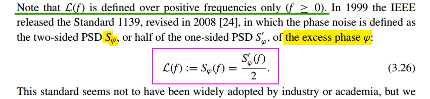
using the narrow angle assumption, the two definitions above are equivalent
If the narrow angle condition is not satisfied, however, the two definitions differ
Sam Palermo, ECEN620: Network Theory Broadband Circuit Design Fall 2025, Lecture 7: Voltage-Controlled Oscillators[https://people.engr.tamu.edu/spalermo/ecen620/lecture07_ee620_vcos.pdf]
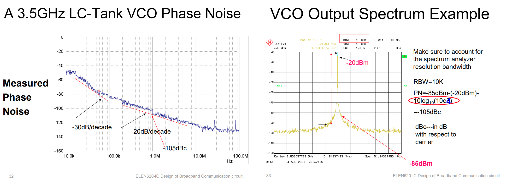
Phase Noise Profile
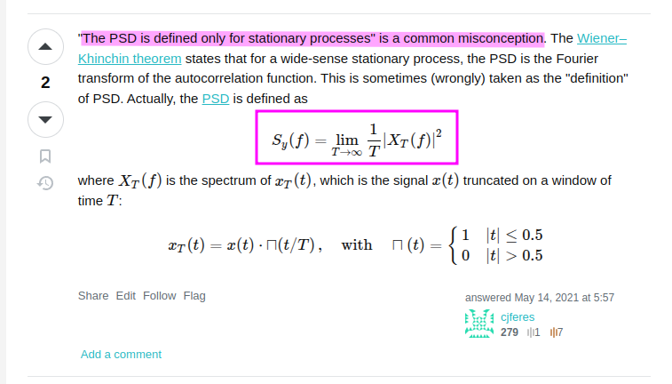
Power Spectral Density of Brownian Motion despite non-stationary [https://dsp.stackexchange.com/a/75043/59253]
white noise — \(1/f^2\) Phase Noise Profile
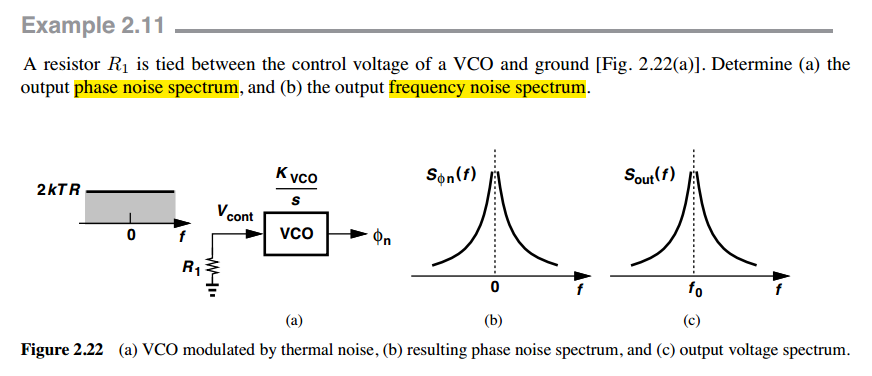
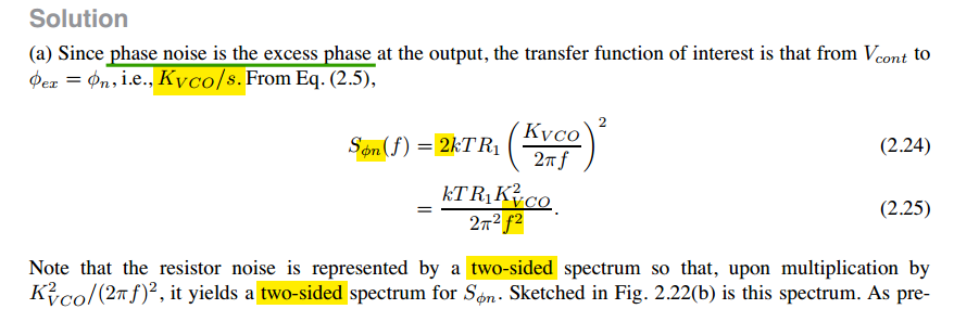
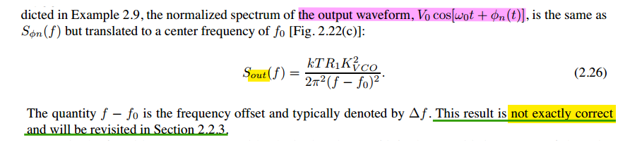
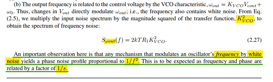
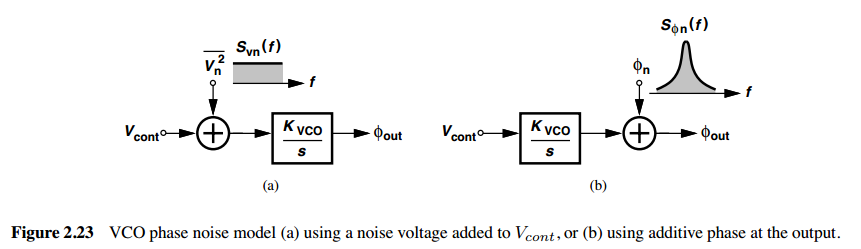
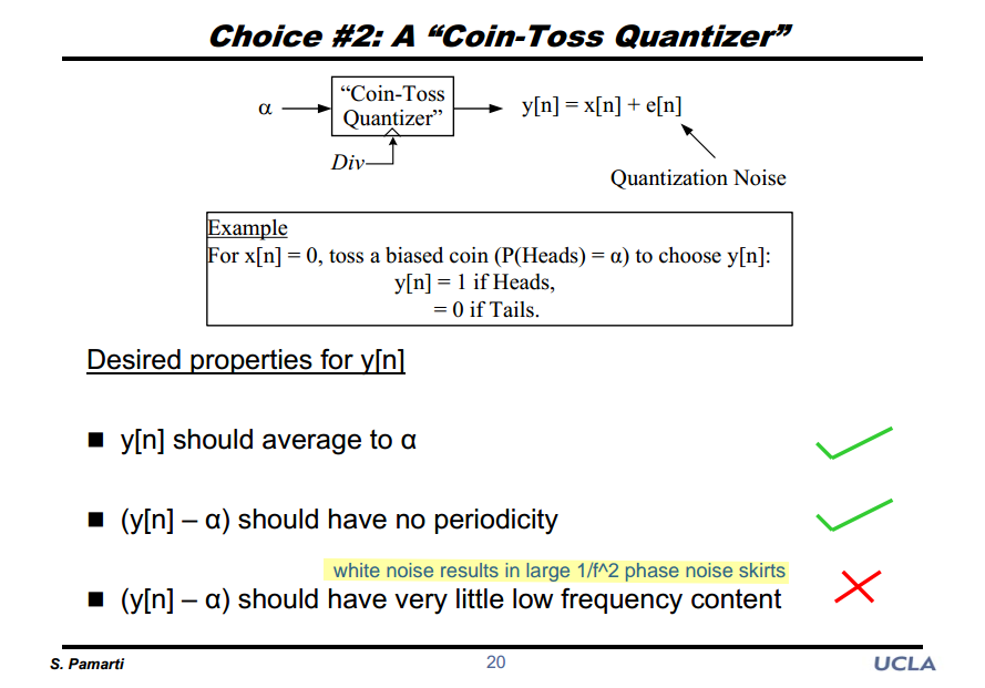
Sudhakar Pamarti. CICC 2020 ES2-2: Basics of Closed- and Open-Loop Fractional Frequency Synthesis [https://youtu.be/t1TY-D95CY8]
flicker noise — \(1/f^3\) Phase Noise Profile \[ S_{\phi n} = \frac{K}{f}\left(\frac{K_{VCO}}{2\pi f}\right)^2 \propto \frac{1}{f^3} \]
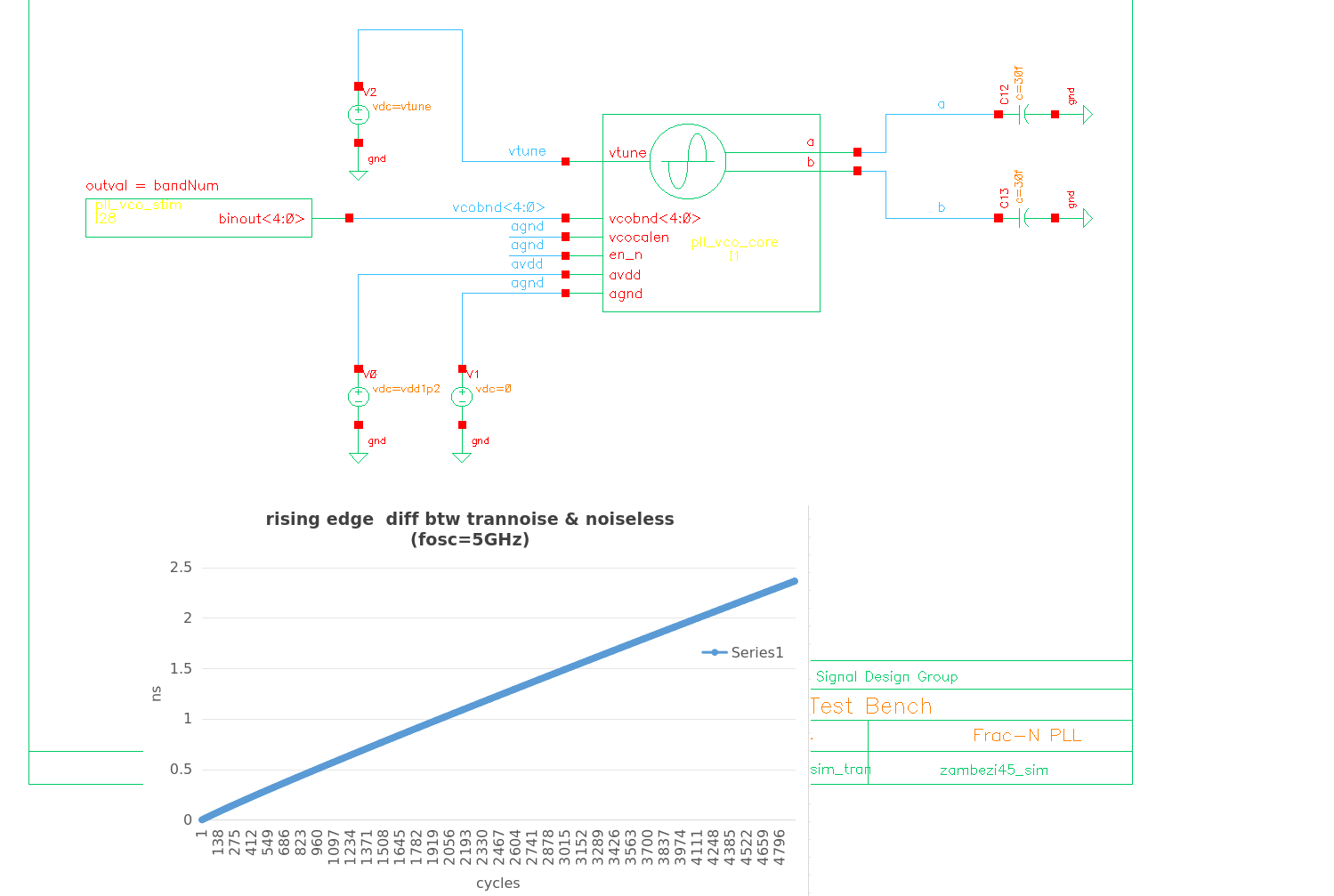
Free-running Oscillator
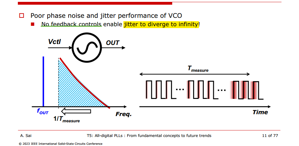
Note that \(f_{min}\) is related to the observation time. The longer we observe the device under test, the smaller \(f_{min}\) must be
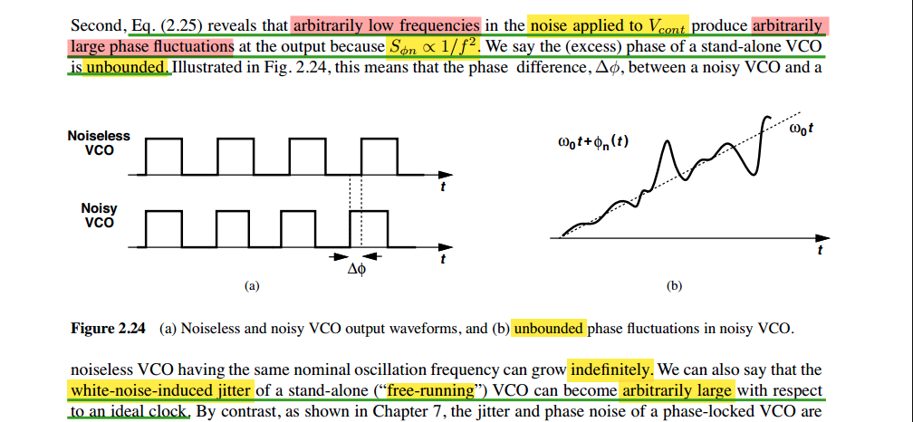
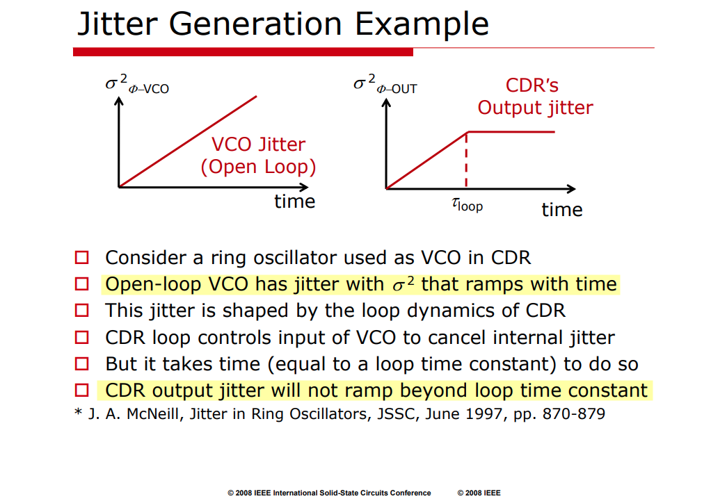
Ali Sheikholeslami ISSCC 2008 T5: Basics of Chip-to-Chip and Backplane Signaling
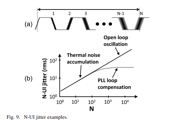
B. Casper and F. O'Mahony, "Clocking Analysis, Implementation and Measurement Techniques for High-Speed Data Links-A Tutorial," in IEEE Transactions on Circuits and Systems I. [https://people.engr.tamu.edu/spalermo/ecen689/clocking_analysis_hs_links_casper_tcas1_2009.pdf]
Equipartition theorem
Carlo Samori, Phase Noise in LC Oscillators: From Basic Concepts to Advanced Topologies [https://www.ieeetoronto.ca/wp-content/uploads/2020/06/DL-VCO-short.pdf]
Enrico Rubiola. The Measurement of AM-PM Noise, and the Origin of Noise in Oscillators [https://rubiola.org/pdf-slides/2010T-ANL-Noise-and-oscillators.pdf]
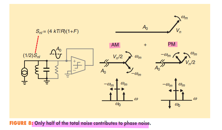
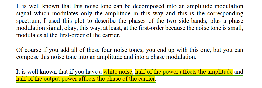
Stationary noise can also be decomposed into AM and PM components, but there will always be equal amounts of both.
Leeson's model — LTI
M.H. Perrott, Short Course On Phase-Locked Loops and Their Applications Day 2, AM Lecture Basic Building Blocks Voltage-Controlled Oscillators [https://www.cppsim.com/PLL_Lectures/day2_am.pdf]
—, 6.976 High Speed Communication Circuits and Systems Lecture 12 Noise in Voltage Controlled Oscillators [https://ocw.mit.edu/courses/6-976-high-speed-communication-circuits-and-systems-spring-2003/ceb3d539691d5393a29af71ae98afb62_lec12.pdf]
Leeson's model is outcome of linearized VCO noise analysis
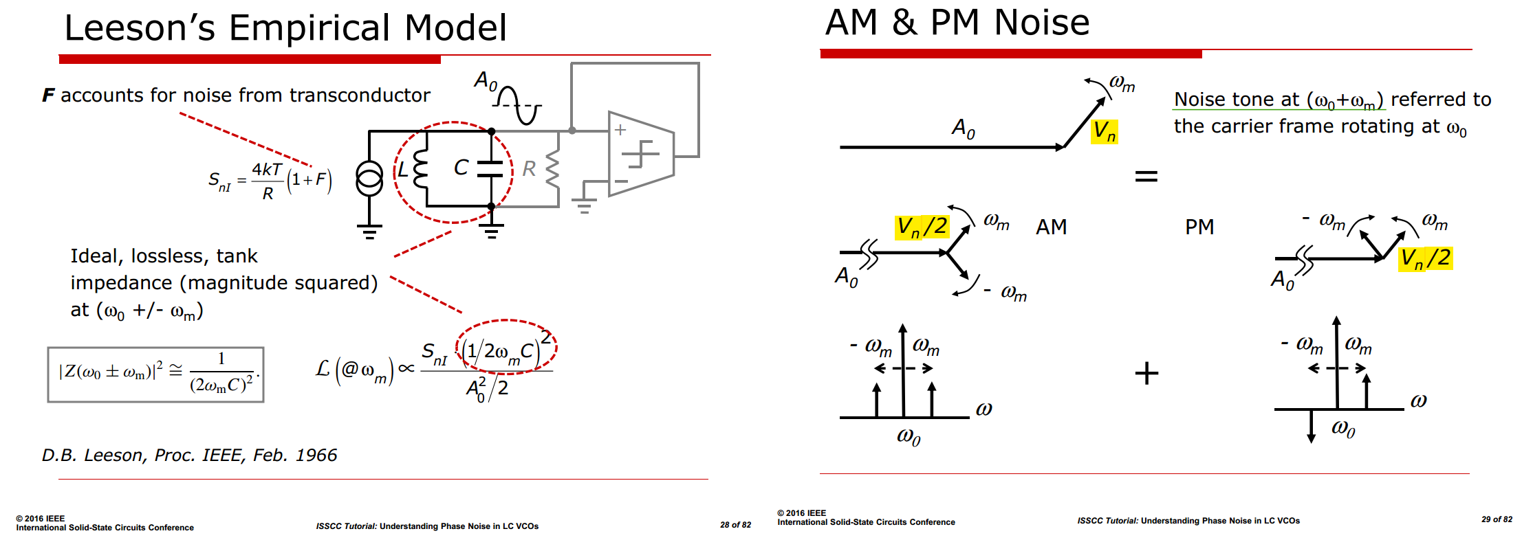
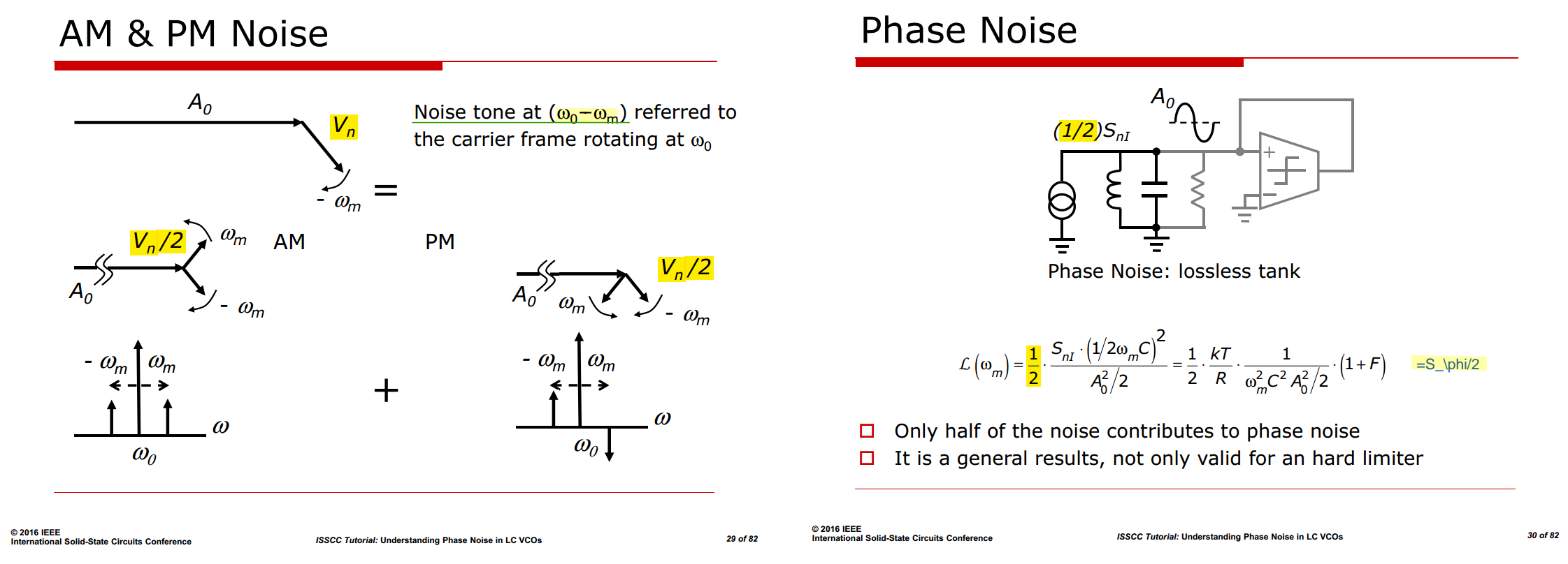
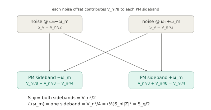
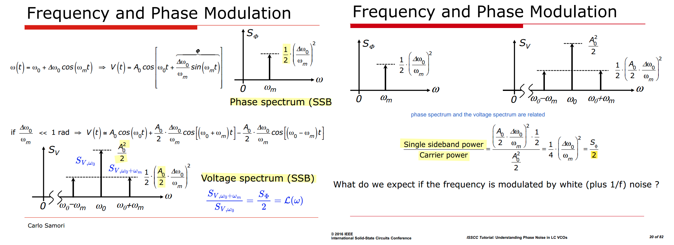
Assuming voltage noise tone \((\omega_0+\omega_m)\) and \((\omega_0-\omega_m)\) are independent and symmetric
Leeson's limitations
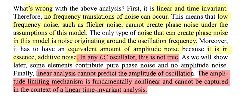
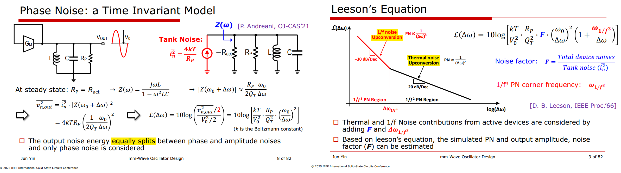
1/f noise Upconversion & Thermal noise Upconversion
Hajimiri's ISF— LTV in Time Domain
A. Hajimiri and T. H. Lee, "A general theory of phase noise in electrical oscillators," in IEEE Journal of Solid-State Circuits, vol. 33, no. 2, pp. 179-194, Feb. 1998 [paper], [slides]
—, RFIC 2024 Technical Lecture: Noise in Oscillators from Understanding to Design
Thomas H. Lee. Linearity, Time-Variation, Phase Modulation and Oscillator Phase Noise [https://class.ece.iastate.edu/djchen/ee507/PhaseNoiseTutorialLee.pdf]
Aditya Varma Muppala, [https://adityamuppala.github.io/assets/Notes_YouTube/Oscillators_ISF_model.pdf]
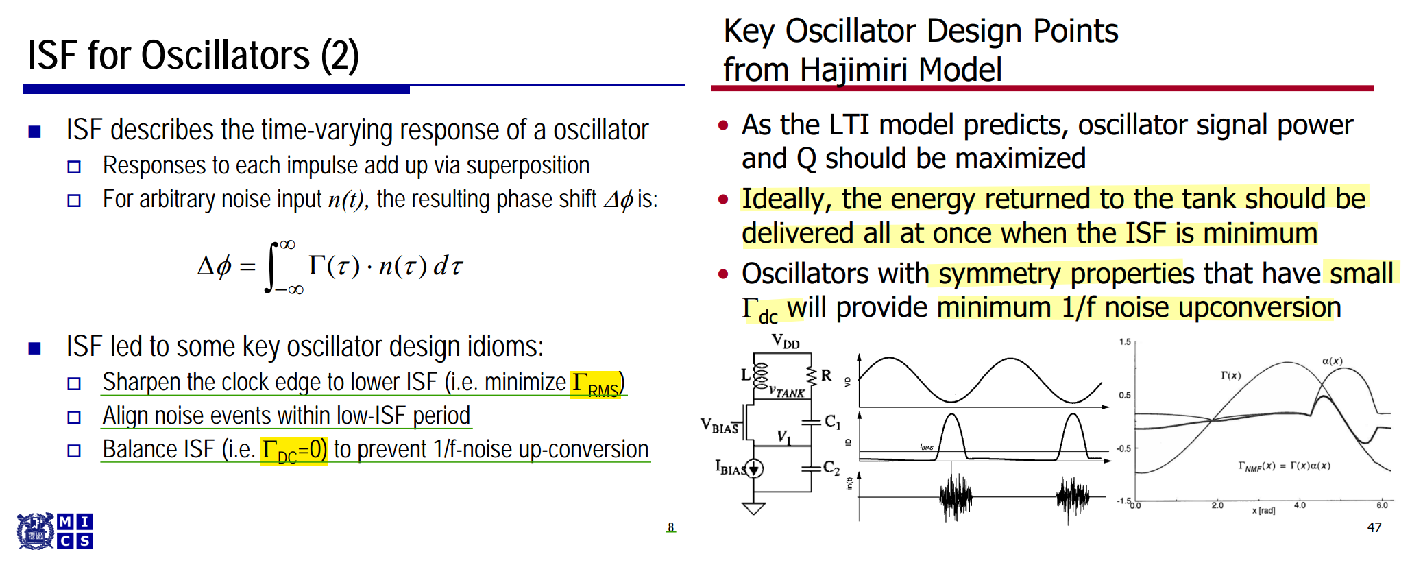
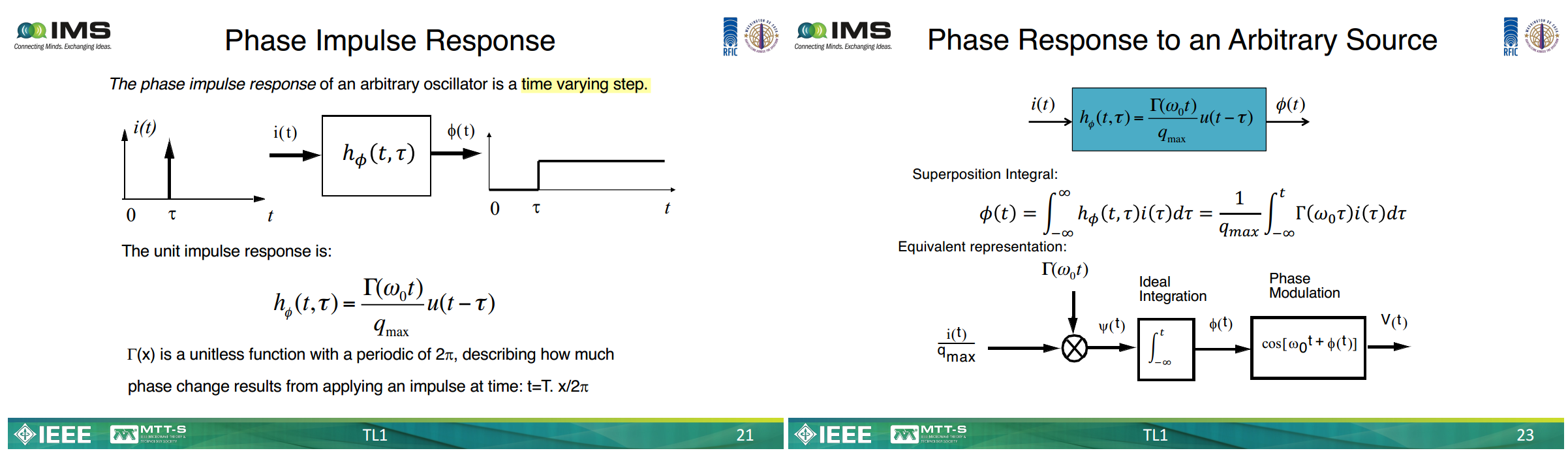
The peak magnitude of the ISF, \[ \Gamma_{\max}=\max_\theta |\Gamma(\theta)|, \] can be greater than 1, equal to 1, or less than 1.
A value \(\Gamma>1\) therefore does not mean "more than 100%." It simply means that the oscillator has relatively high phase sensitivity at that particular phase.
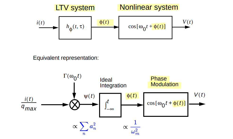

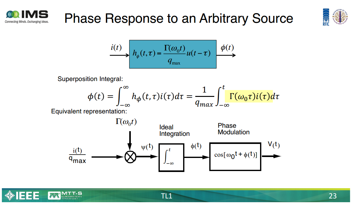
\(\psi(t)\) is literally the instantaneous frequency deviation. Check the dimensions: \(i(t)/q_{max}\) has units of A/C = 1/s, and \(\Gamma\) is dimensionless, so \(\psi(t) = \Gamma(\omega_0 t)\,i(t)/q_{max}\) is in rad/s. The diagram is saying \(d\phi/dt = \psi(t)\), i.e. \(\phi(t) = \int_{-\infty}^{t}\psi(\tau)d\tau\). An ideal integrator has transfer function \(1/j\Delta\omega\), so in power spectra: \[ S_\phi(\Delta\omega) = \frac{S_\psi(\Delta\omega)}{\Delta\omega^2} \] That single block is the origin of every \(1/\Delta\omega^2\) factor in phase noise theory — including the \((\omega_0/2Q\Delta\omega)^2\) term in Leeson's equation
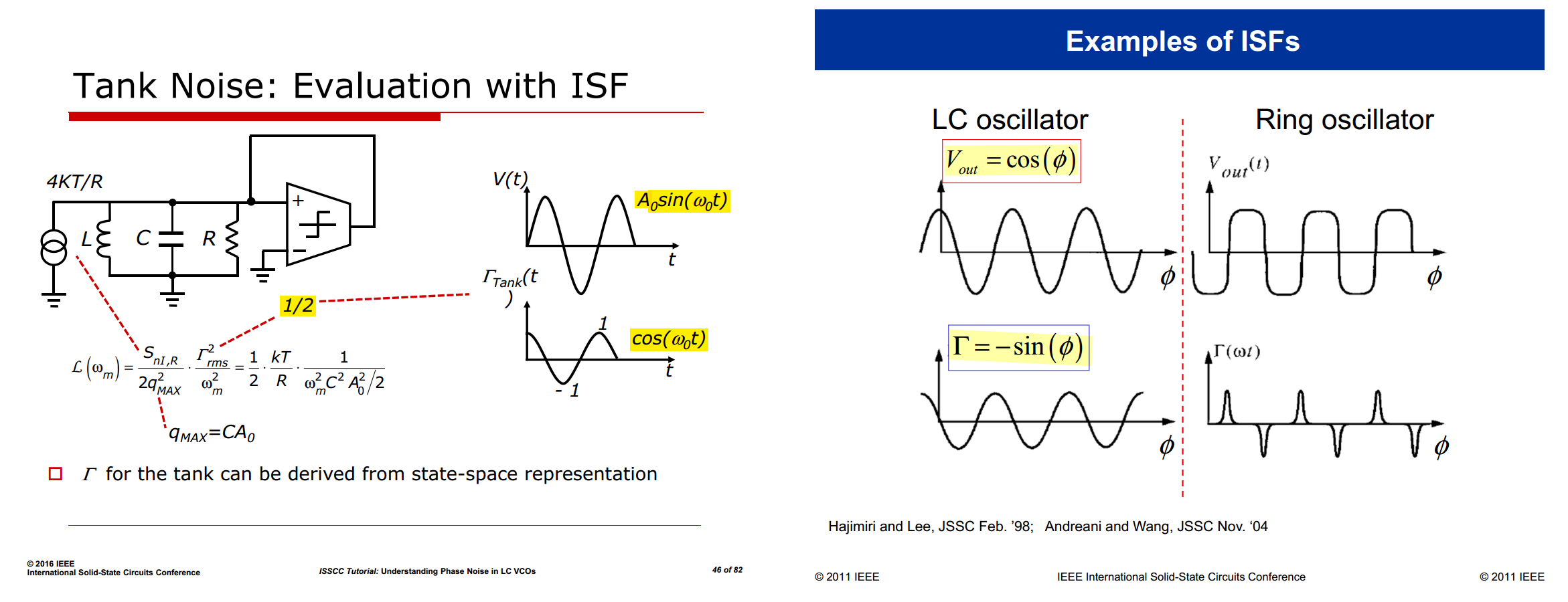
Pure sinusoidal voltage
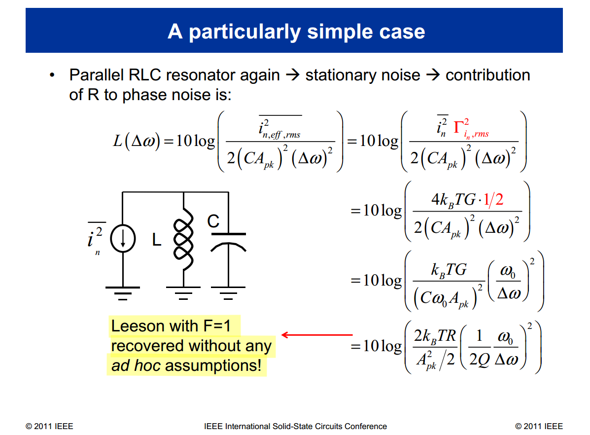
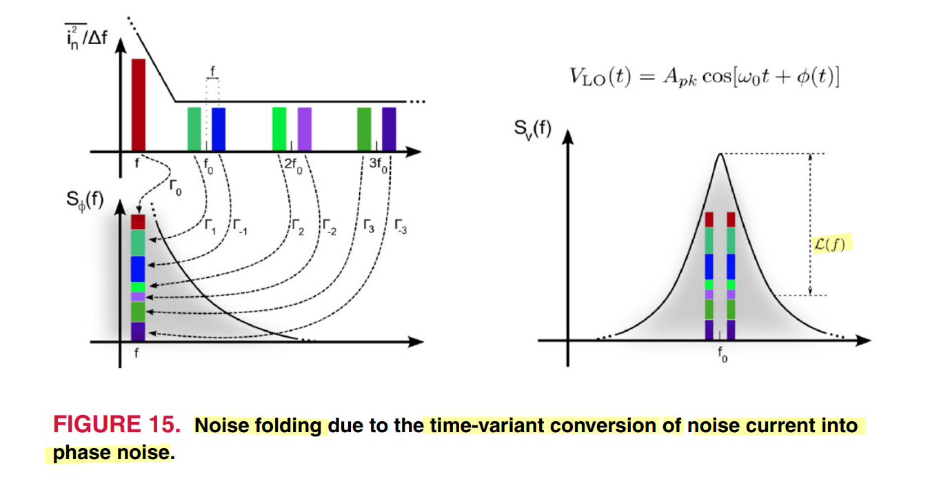
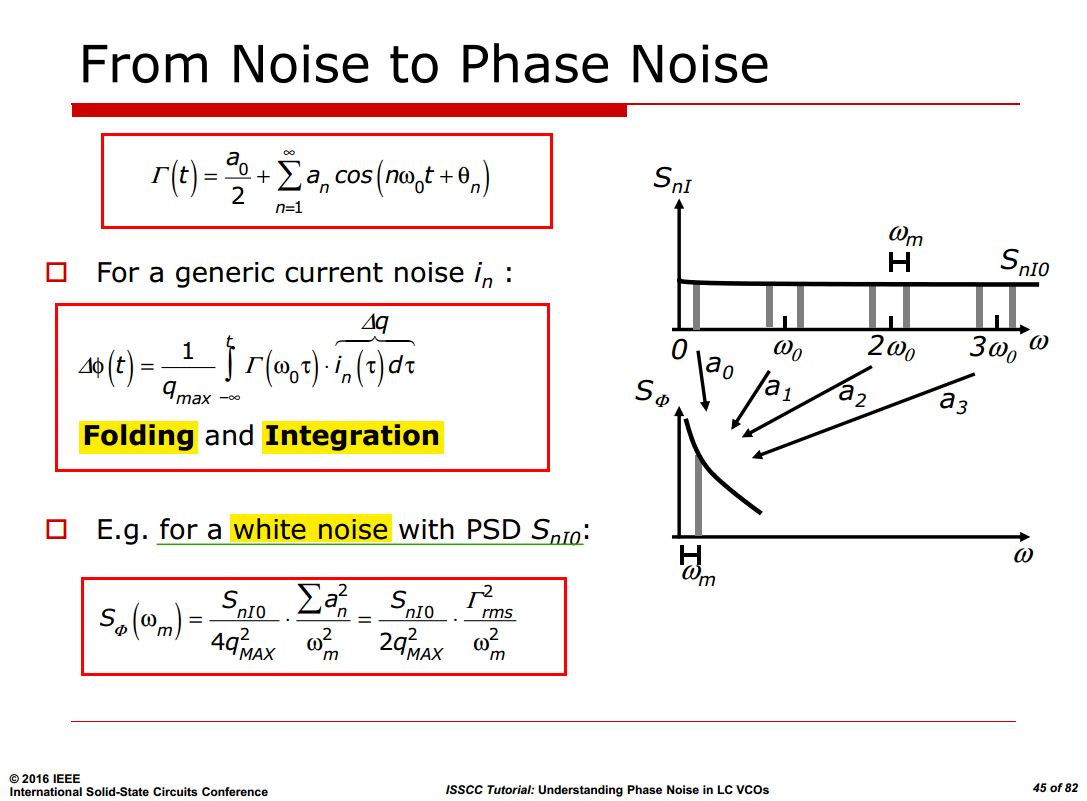
White-noise Folding
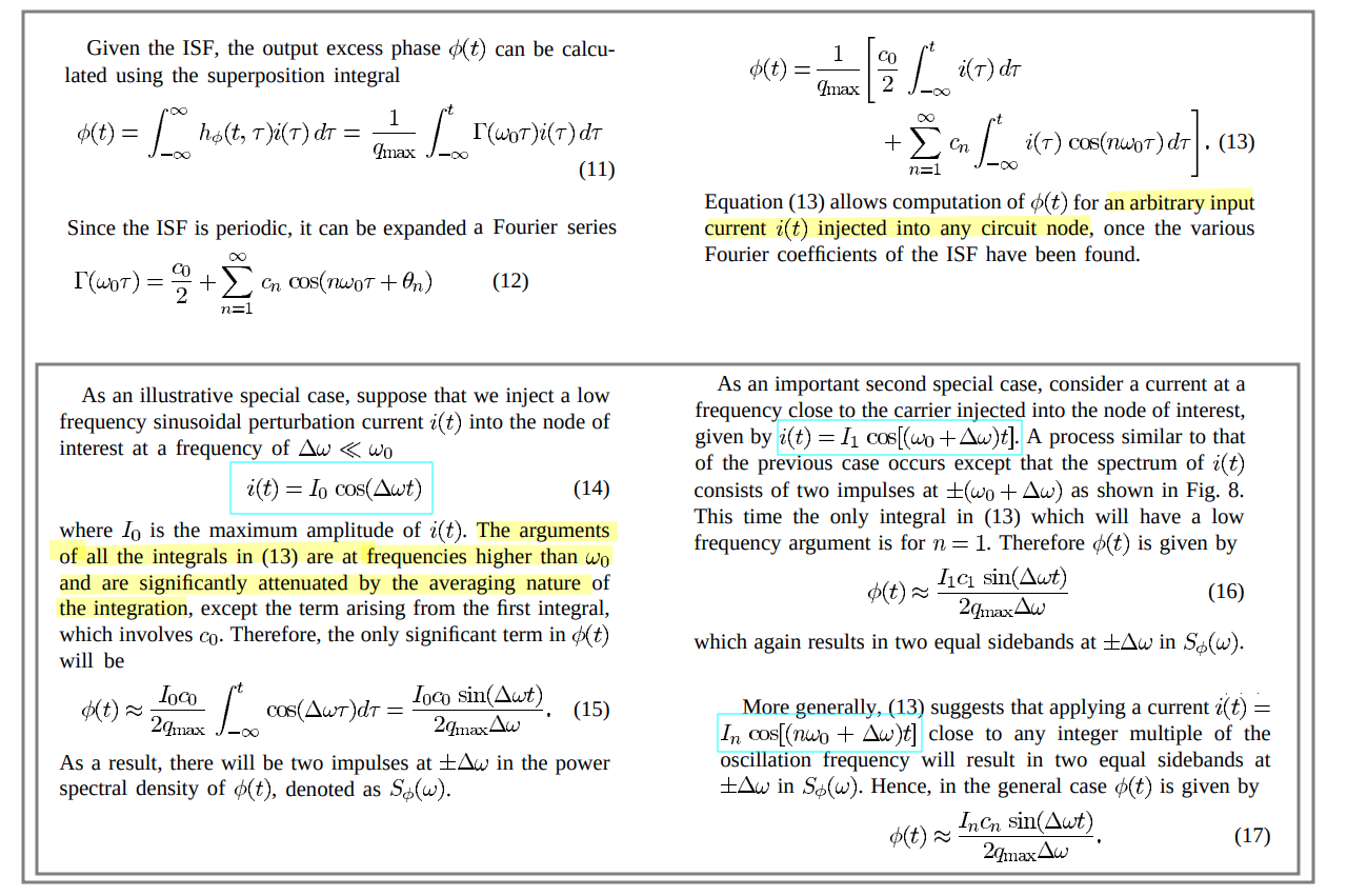
Suppose a low frequency sinusoidal perturbation current \(i(t) = I_m \cos[(m\omega_0 +\Delta \omega)t]\),
\[\begin{align} \phi(t) &= \frac{1}{q_\text{max}}\left[\frac{C_0}{2}\int_{-\infty}^t I_m\cos((m\omega_0 +\Delta \omega)\tau)d\tau + \sum_{n=1}^\infty C_n\int_{-\infty}^t I_m\cos((m\omega_0 +\Delta \omega)\tau)\cos(n\omega_0\tau)d\tau\right] \\ &= \frac{I_m}{q_\text{max}}\left[\frac{C_0}{2}\int_{-\infty}^t \cos((m\omega_0 +\Delta \omega)\tau)d\tau + \sum_{n=1}^\infty C_n\int_{-\infty}^t \frac{\cos((m\omega_0 + \Delta \omega+ n\omega_0)\tau)+ \cos((m\omega_0+\Delta \omega - n\omega_0)\tau)}{2}d\tau\right] \end{align}\]
If \(m=0\) \[ \phi(t) \approx \frac{I_0C_0}{2q_\text{max}\Delta \omega}\sin(\Delta\omega t) \] If \(m\neq 0\) and \(m=n\) \[ \phi(t) \approx \frac{I_mC_m}{2q_\text{max}\Delta \omega}\sin(\Delta\omega t) \]
When performing the phase noise computation integral, there will be a negligible contribution from all terms, other than \(n=m\)
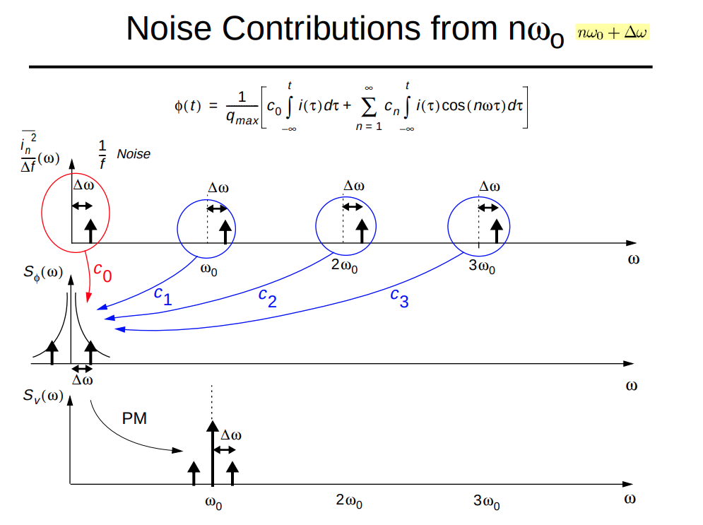
apply equation (18) derived from sinusoidal to white noise
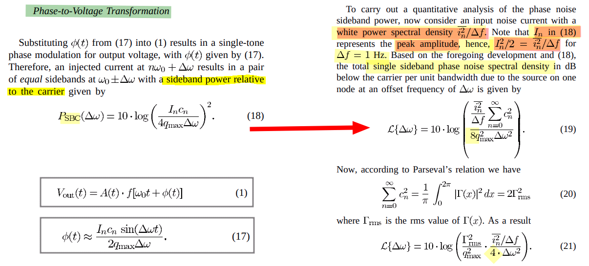
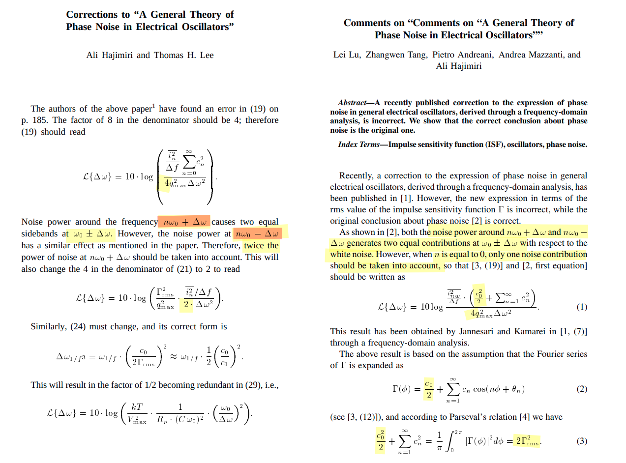
Corrections to "A General Theory of Phase Noise in Electrical Oscillators"
A. Hajimiri and T. H. Lee, "Corrections to "A General Theory of Phase Noise in Electrical Oscillators"," in IEEE Journal of Solid-State Circuits, vol. 33, no. 6, pp. 928-928, June 1998 [https://sci-hub.se/10.1109/4.678662]
L. Lu, Z. Tang, P. Andreani, A. Mazzanti and A. Hajimiri, "Comments on “Comments on “A General Theory of Phase Noise in Electrical Oscillators””," in IEEE Journal of Solid-State Circuits, vol. 43, no. 9, pp. 2170-2170, Sept. 2008 [https://sci-hub.se/10.1109/JSSC.2008.2005028]
Noise power around the frequency \(\color{blue}n\omega_0 + \Delta\omega\) causes two equal sidebands at \(\omega_0 \pm \Delta\omega\). However, the noise power at \(\color{blue}n\omega_0 - \Delta\omega\) has a similar effect as mentioned in the paper. Therefore, twice the power of noise at \(n\omega_0 + \Delta\omega\) should be taken into account
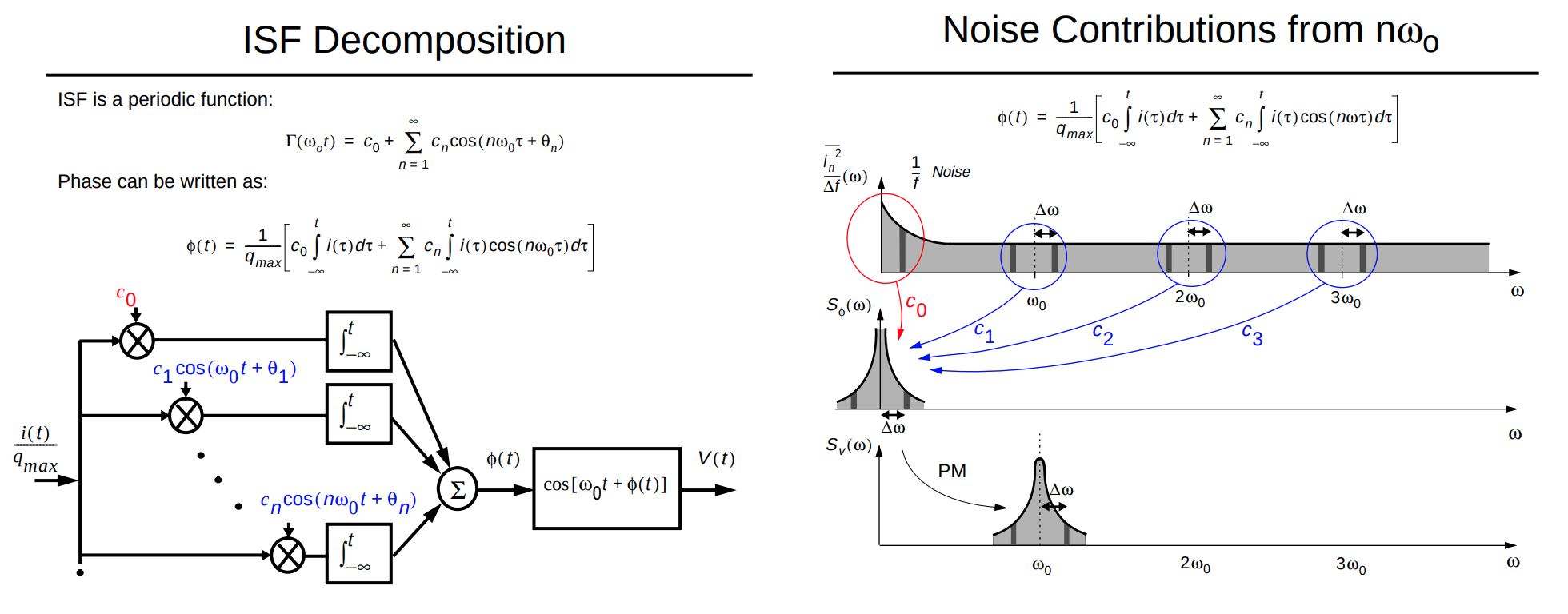
Given \(i(t) = I_m \cos[(m\omega_0 - \Delta \omega)t]\) and \(m \ge 1\)
\[\begin{align} \phi(t) &= \frac{1}{q_\text{max}}\left[\frac{C_0}{2}\int_{-\infty}^t I_m\cos((m\omega_0 -\Delta \omega)\tau)d\tau + \sum_{n=1}^\infty C_n\int_{-\infty}^t I_m\cos((m\omega_0 -\Delta \omega)\tau)\cos(n\omega_0\tau)d\tau\right] \\ &= \frac{I_m}{q_\text{max}}\left[\frac{C_0}{2}\int_{-\infty}^t \cos((m\omega_0 -\Delta \omega)\tau)d\tau + \sum_{n=1}^\infty C_n\int_{-\infty}^t \frac{\cos((m\omega_0 - \Delta \omega+ n\omega_0)\tau)+ \cos((m\omega_0-\Delta \omega - n\omega_0)\tau)}{2}d\tau\right] \end{align}\]
If \(m\ge 1\) and \(m=n\) \[ \phi(t) \approx \frac{I_mC_m}{2q_\text{max}\Delta \omega}\sin(\Delta\omega t) \] That is
| \(m = 0\) | \(m\gt 0\) & \(m\omega_0+\Delta \omega\) | \(m\gt 0\) & \(m\omega_0-\Delta \omega\) | |
|---|---|---|---|
| \(\phi(t)\) | \(\frac{I_0C_0}{2q_\text{max}\Delta \omega}\sin(\Delta\omega t)\) | \(\frac{I_mC_m}{2q_\text{max}\Delta \omega}\sin(\Delta\omega t)\) | \(\frac{I_mC_m}{2q_\text{max}\Delta \omega}\sin(\Delta\omega t)\) |
| \(P_{SBC}(\Delta \omega)\) | \(10\log(\frac{I_0^2C_0^2}{16q_\text{max}^2\Delta \omega^2})\) | \(10\log(\frac{I_m^2C_m^2}{16q_\text{max}^2\Delta \omega^2})\) | \(10\log(\frac{I_m^2C_m^2}{16q_\text{max}^2\Delta \omega^2})\) |
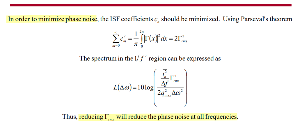
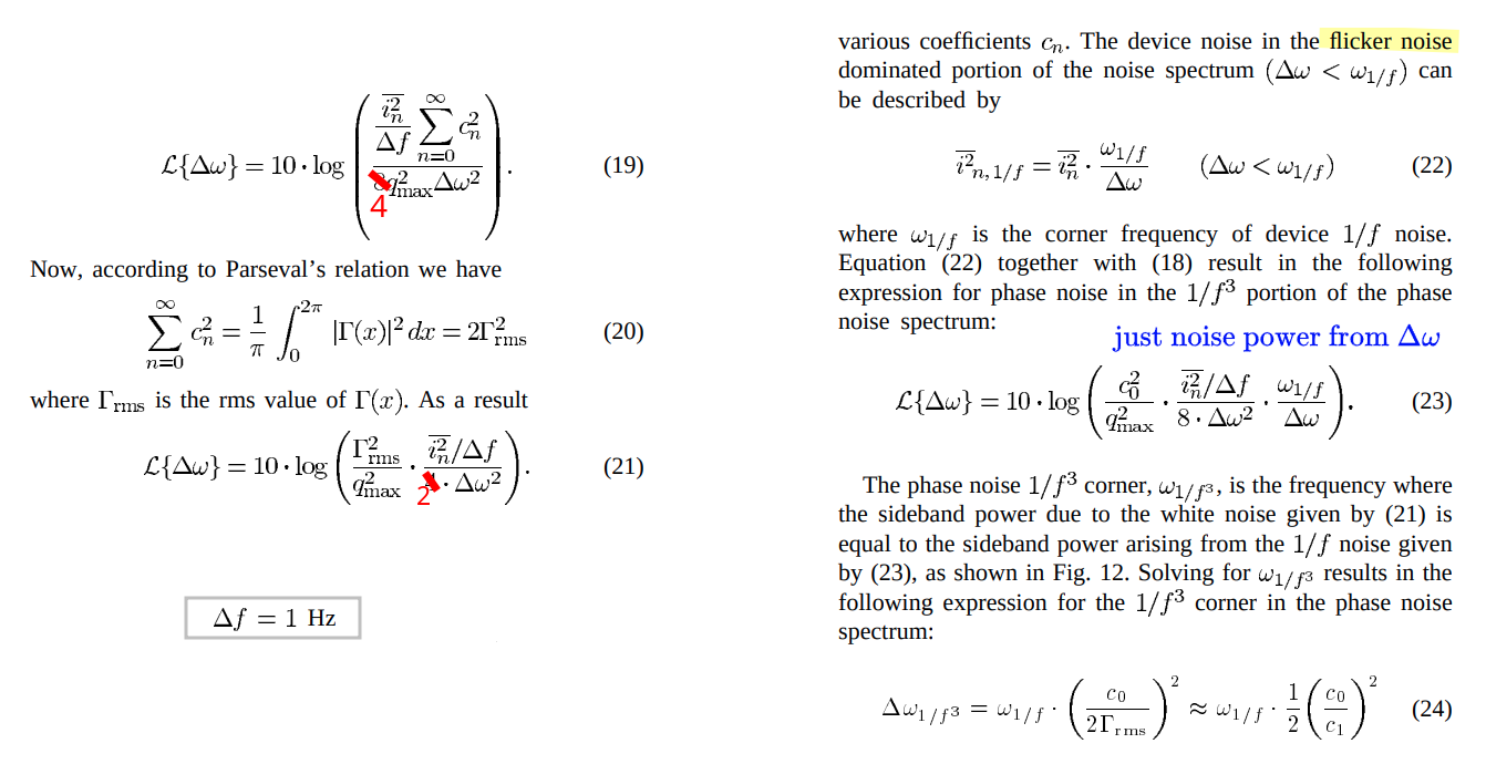
\[\begin{align} \mathcal{L}\{\Delta \omega\} &= 10\log\left(\frac{I_0^2C_0^2}{16q_\text{max}^2\Delta \omega^2} + 2\frac{I_m^2C_m^2}{16q_\text{max}^2\Delta \omega^2}\right) = 10\log\left(\frac{\overline{i_n^2/\Delta f}\cdot \frac{C_0^2}{2} }{4q_\text{max}^2\Delta \omega^2} + \frac{\overline{i_n^2/\Delta f}\cdot\sum_{m=1}^\infty C_m^2 }{4q_\text{max}^2\Delta \omega^2}\right) \\ &= 10\log \frac{\overline{i_n^2/\Delta f}(C_0^2/2+\sum_{m=1}^\infty C_m^2)}{4q_\text{max}^2\Delta \omega^2} = 10\log \frac{\overline{i_n^2/\Delta f}\cdot \Gamma_\text{rms}^2}{2q_\text{max}^2\Delta \omega^2} \end{align}\]
[pdf]
1/f-noise Upconversion
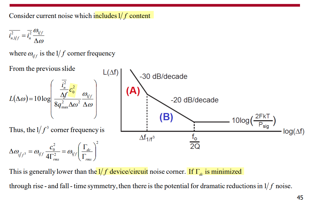
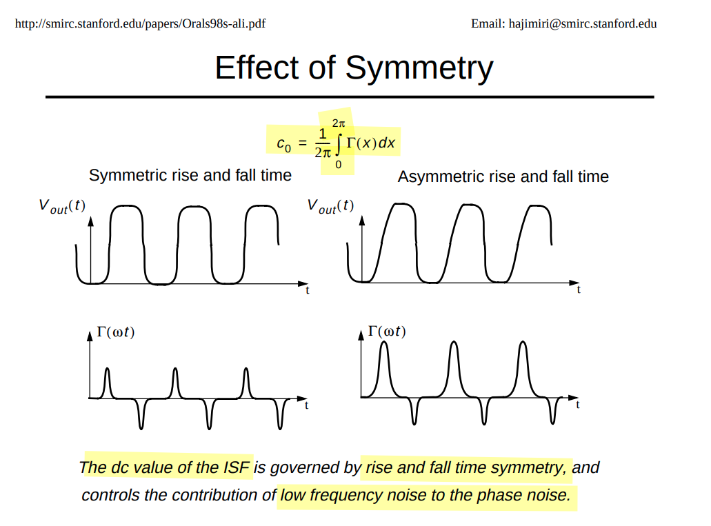
Suppose \(c_0\neq 0\), corresponding phase noise in response to injected noise \(i_n(t)\) is equal to:
\[ \phi_{n,c_0} = \int_{-\infty}^t c_0 i_n(\tau) d\tau \qquad \boxed{S_{\phi n,c_0}(f) = \frac{c_0^2}{\omega^2}S_i(f)= \frac{\mathcal{\Gamma}_\text{dc}^2}{\omega^2}S_i(f)} \]
alternative derivation
Michael Perrott August 12, 2008, Short Course On Phase-Locked Loops and Their Applications Day 2, AM Lecture Basic Building Blocks Voltage-Controlled Oscillators [https://www.cppsim.com/PLL_Lectures/day2_am.pdf]
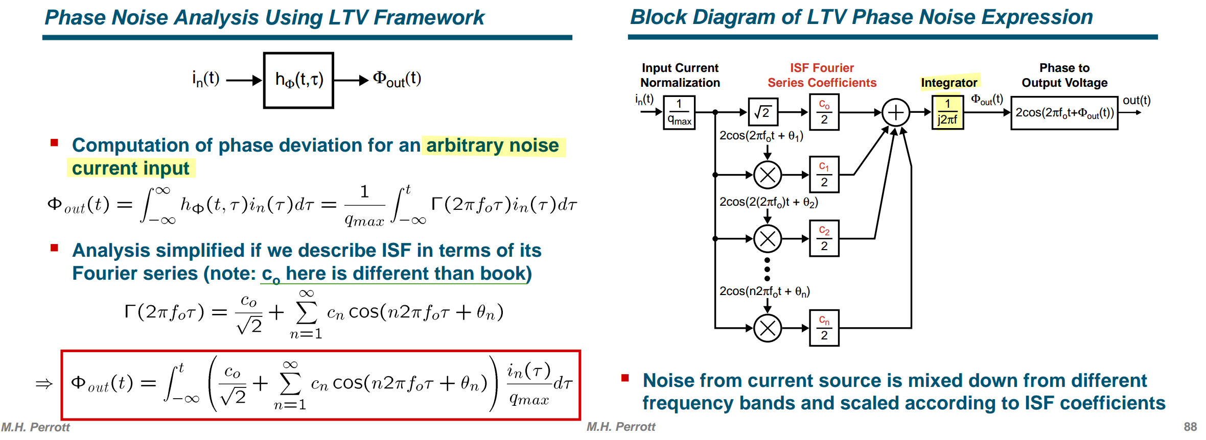
White Noise Input
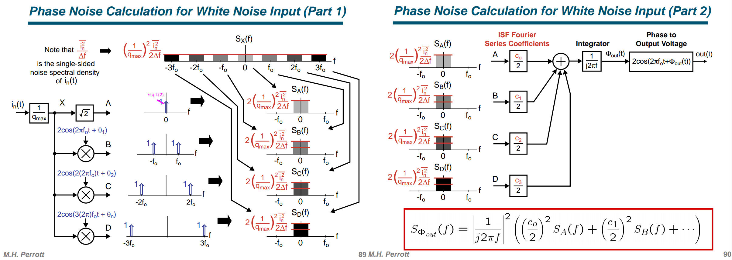
1/f Noise in Input Current
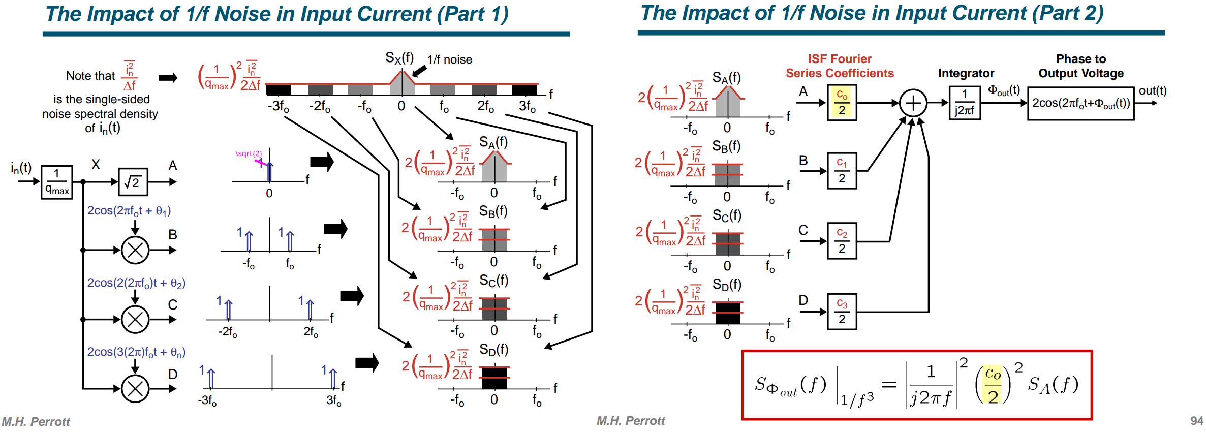
Current Noise Modulation
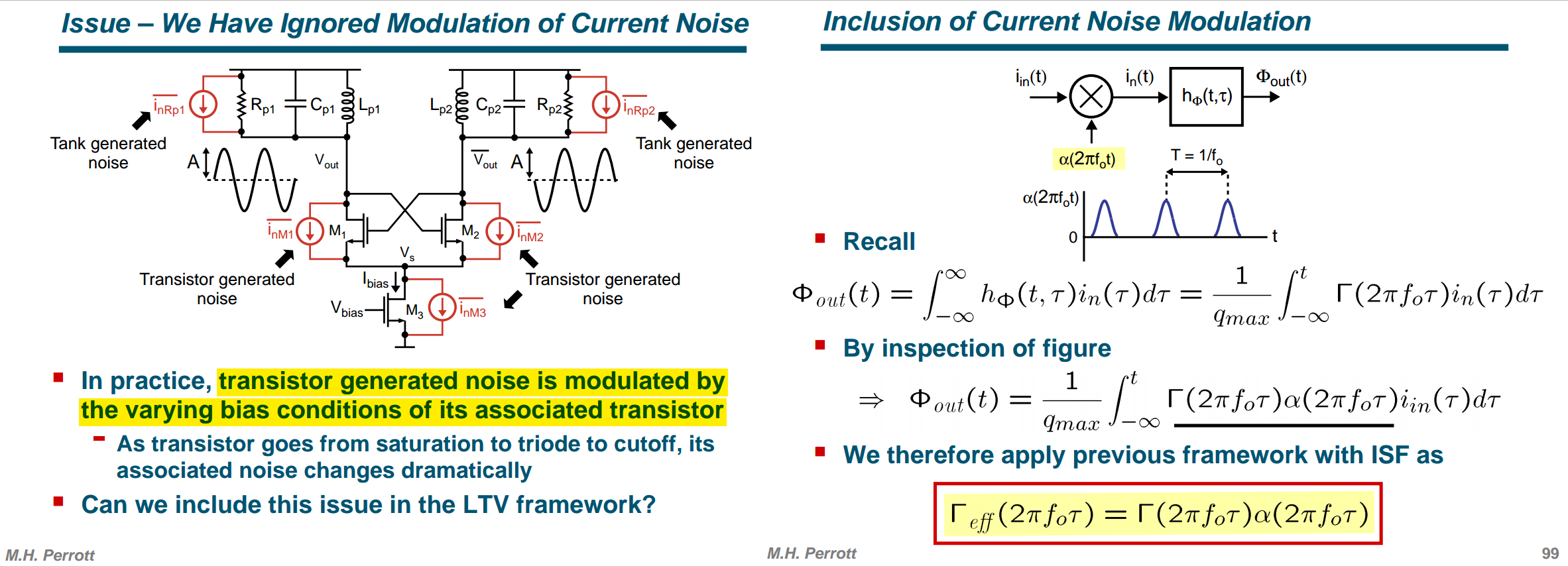
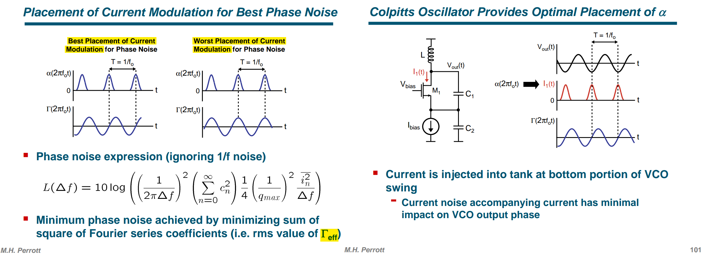
another alternative derivation
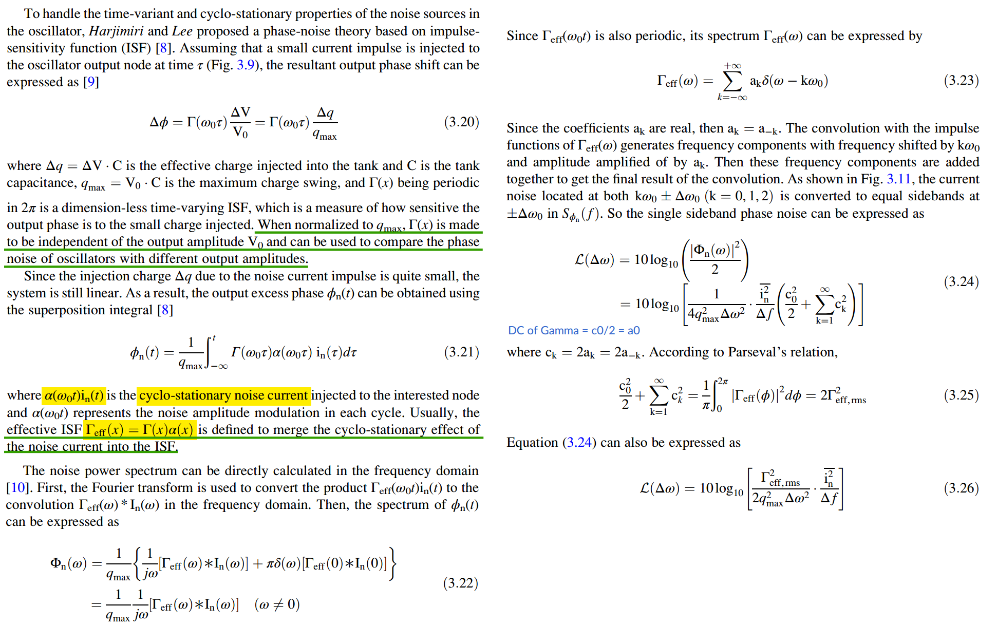
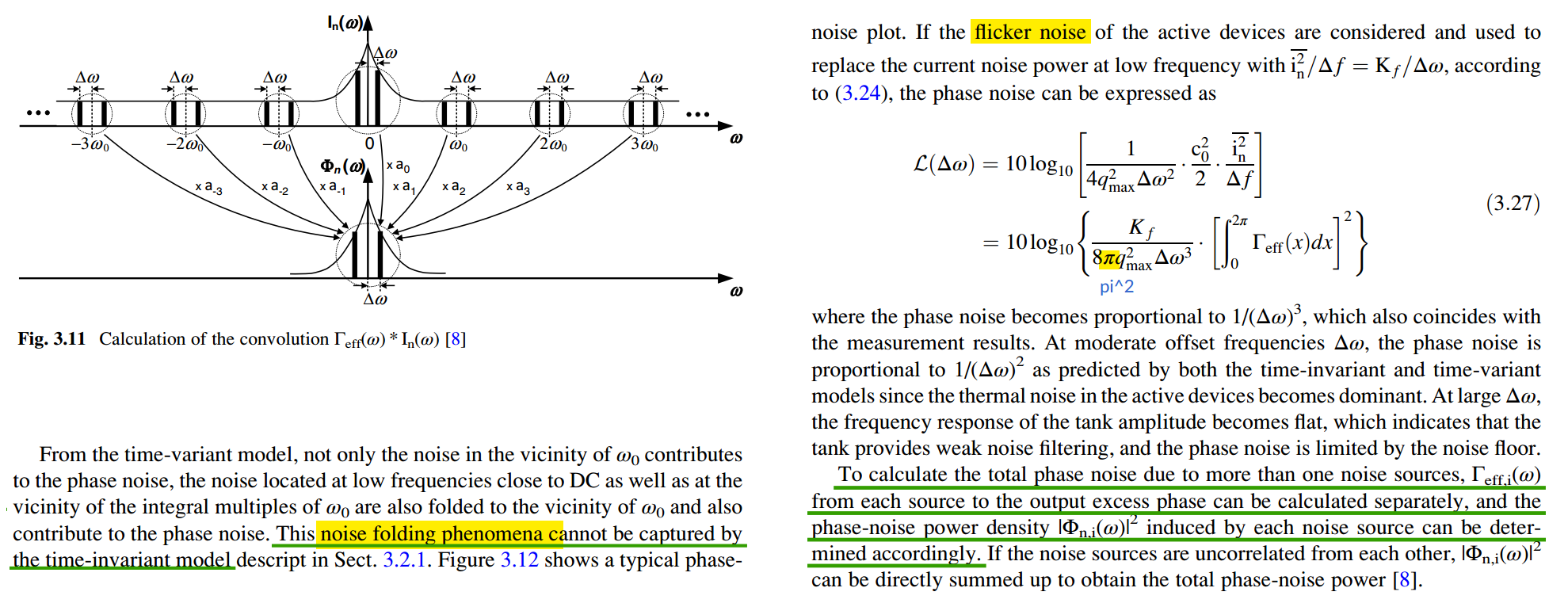
 \[
S_{\phi,USB} =
\frac{S_n^{''}}{q_\text{max}^2\Delta\omega^2}\left(a_0^2+\sum_{k\neq0}a_k^2\right)=\frac{S_n^{''}}{q_\text{max}^2\Delta\omega^2}\left(\frac{c_0^2}{4}+\sum_{k=1}^\infty
\frac{c_k^2}{2}\right)=\frac{S_n^{'}}{4q_\text{max}^2\Delta\omega^2}\left(\frac{c_0^2}{2}+\sum_{k=1}^\infty
c_k^2\right)
\] where \(S_n^{''}\) is
two sided PSD, \(S_n^{}\) is one sided
PSD
\[
S_{\phi,USB} =
\frac{S_n^{''}}{q_\text{max}^2\Delta\omega^2}\left(a_0^2+\sum_{k\neq0}a_k^2\right)=\frac{S_n^{''}}{q_\text{max}^2\Delta\omega^2}\left(\frac{c_0^2}{4}+\sum_{k=1}^\infty
\frac{c_k^2}{2}\right)=\frac{S_n^{'}}{4q_\text{max}^2\Delta\omega^2}\left(\frac{c_0^2}{2}+\sum_{k=1}^\infty
c_k^2\right)
\] where \(S_n^{''}\) is
two sided PSD, \(S_n^{}\) is one sided
PSD
Diff. Pair Noise with ISF
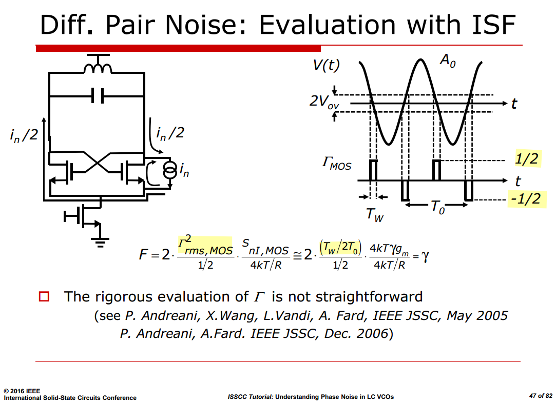
only half of this current is differentially injected in the tank at the zero-crossing

Given \(\Gamma_{MOS}\) shown as above slide \[ F_{rms,MOS}^2 = \frac{1/4\cdot T_\text{w}}{T_0/2} = \frac{T_\text{w}}{2T_0} \]
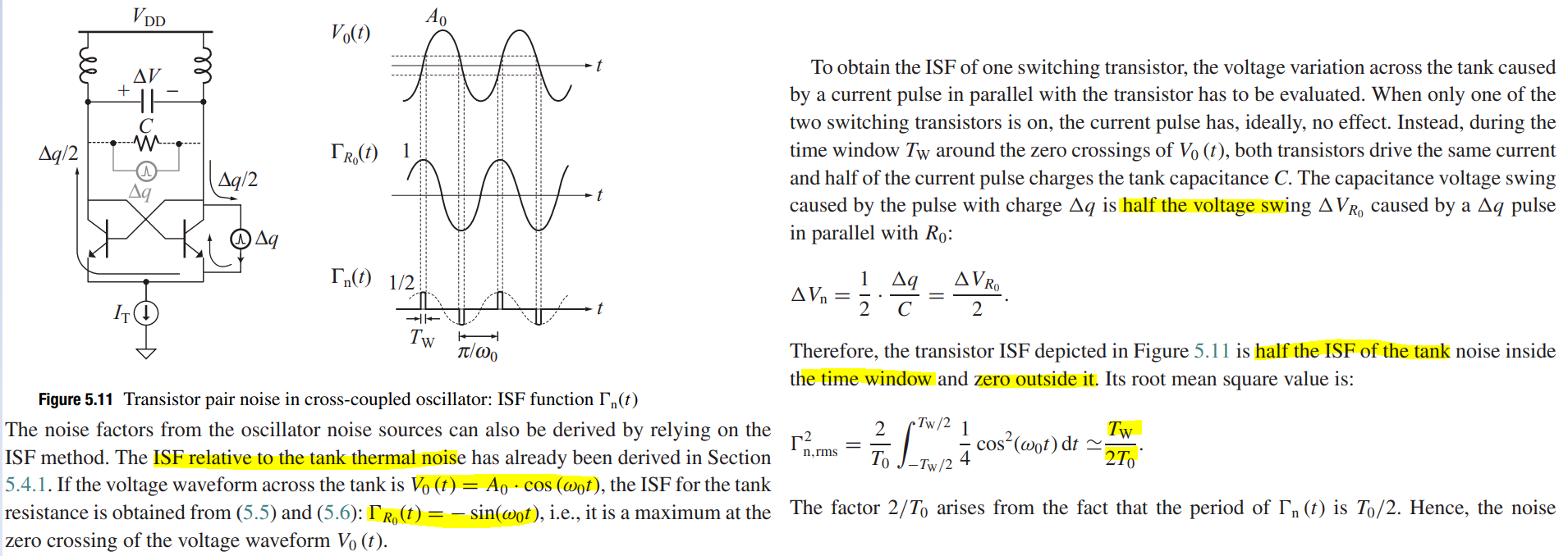
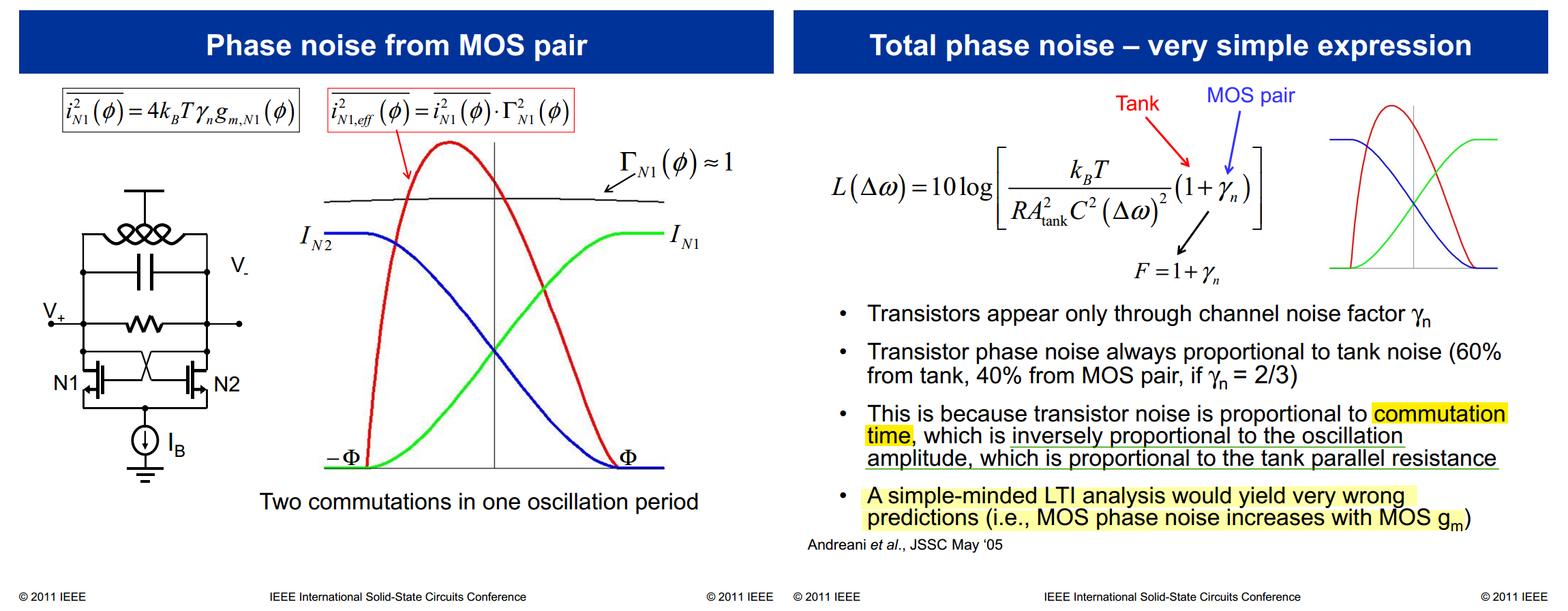
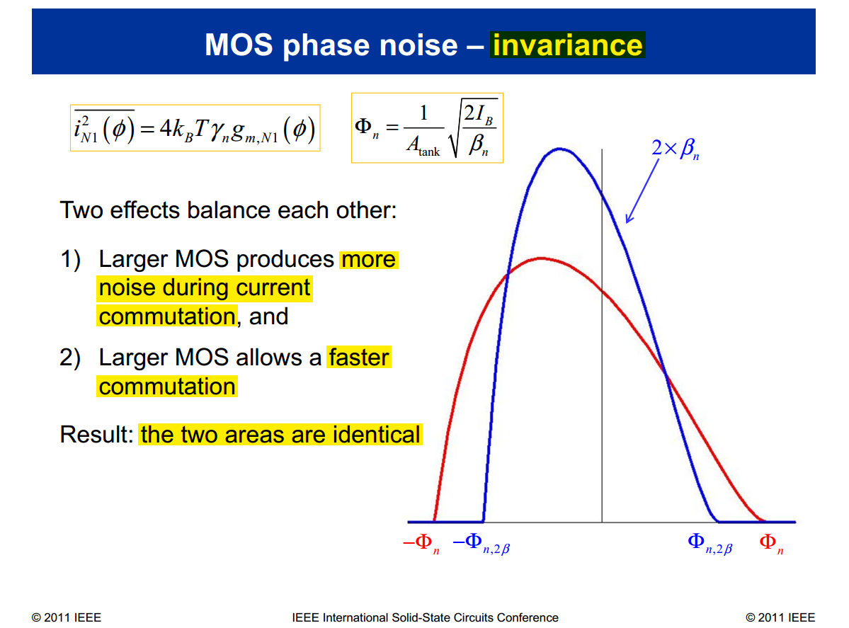
P. Andreani, X. Wang, "On the Phase-Noise and Phase-Error Performances of Multiphase LC CMOS VCOs," IEEE Journal of Solid-State Circuits, vol. 39, pp. 1883-1893, Nov. 2004. [https://backend.orbit.dtu.dk/ws/files/4109919/Wang.pdf]
P. Andreani, X. Wang, L. Vandi, A. Frad, "A study of phase noise in Colpitts and LC-tank CMOS oscillators," IEEE Journal of Solid-State Circuits, vol. 40, pp. 1107-1118, May 2005. [https://backend.orbit.dtu.dk/ws/files/3976825/Andreani.pdf]
A. Bevilacqua, P. Andreani, "An Analysis of 1/f Noise to Phase Noise Conversion in CMOS Harmonic Oscillators," IEEE Transactions on Circuits and Systems I: Regular Papers, vol. 59, no. 5, pp. 938-945, May 2012 [https://sci-hub.jp/10.1109/TCSI.2012.2190564]
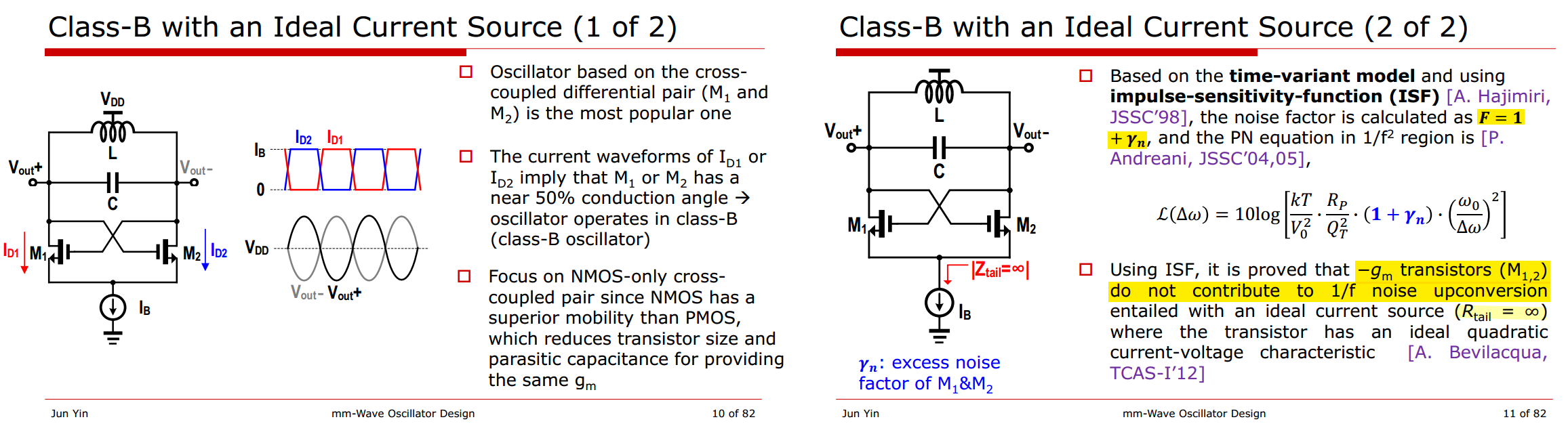
For Class-B with an Ideal Current Source
- noise factor is \(\boxed{1+\gamma_n}\)
- \(-g_m\) transistors (M1,2) do not contribute to \(1/f\) noise upconversion
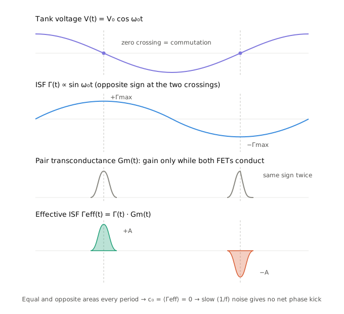
Note the contrast with thermal noise: white noise is uncorrelated between the two crossings, so the two kicks don't cancel — their variances add. That's why the same commutation mechanism gives you the full \(\gamma_n\) term in \(F = 1+\gamma_n\) for the \(1/f^2\) region, yet contributes nothing in \(1/f^3\)
Tail-Current Noise Conversion with the ISF
A. Hajimiri and T. H. Lee, "Design issues in CMOS differential LC oscillators," in IEEE Journal of Solid-State Circuits, vol. 34, no. 5, pp. 717-724, May 1999. [paper]
T. H. Lee, Linearity, Time-Variation, Phase Modulation and Oscillator Phase Noise. [slides]
K. Gunnam and M. VahidFar, eds., Selected Topics in RF, Analog and Mixed Signal Circuits and Systems, 1st ed. River Publishers, 2017.
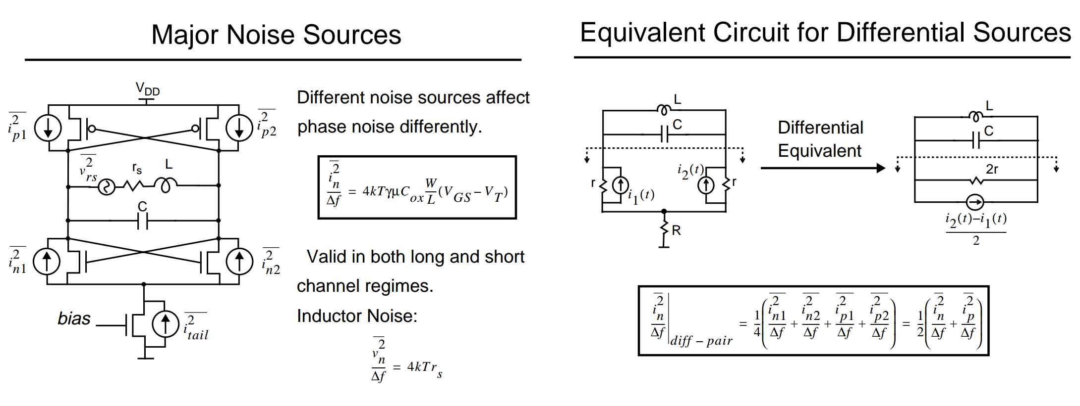
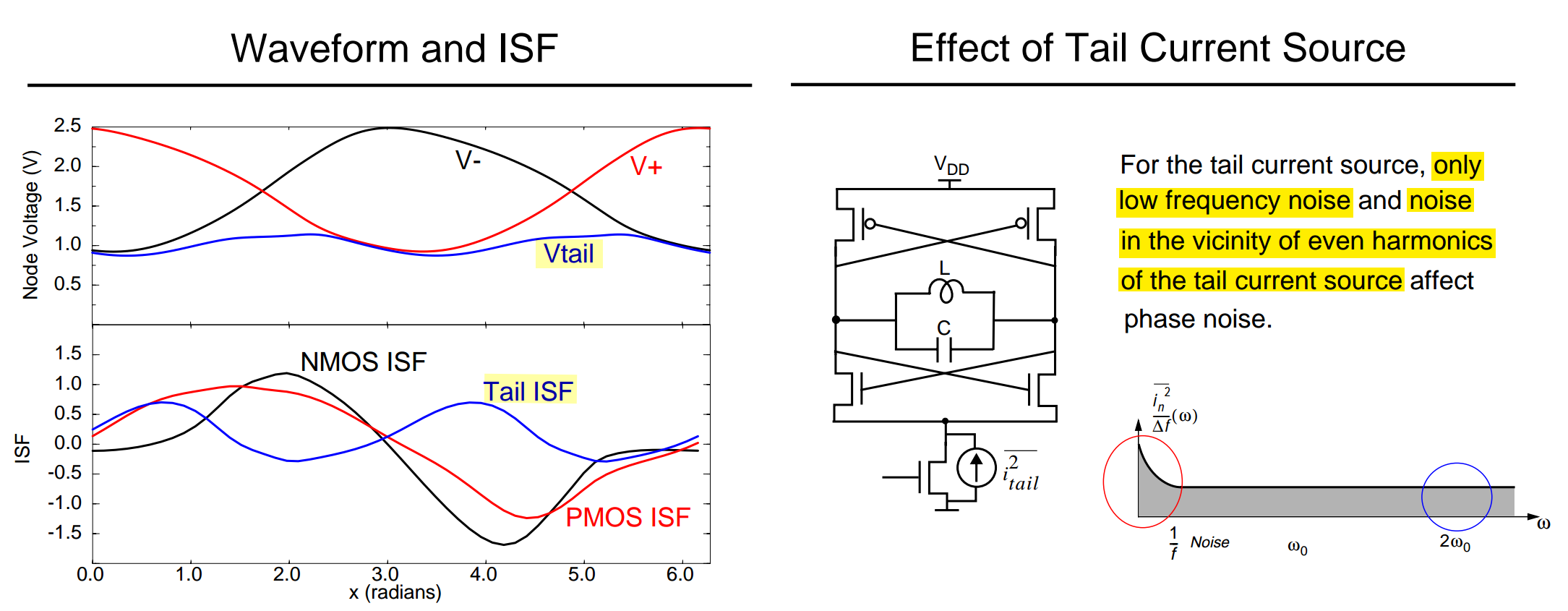
The differential pair commutates twice per oscillation cycle. After half a cycle, the two sides exchange roles, but the common tail node returns to the same state. Therefore, both the tail voltage and the tail-current ISF have half-period symmetry: \[ v_\text{tail}\left(t+\frac{T_0}{2}\right)=v_\text{tail}(t), \qquad \Gamma_\text{tail}(\theta+\pi)=\Gamma_\text{tail}(\theta). \] It follows that the tail ISF can have a DC component but only even harmonics of \(\omega_0\): \[ \Gamma_\text{tail}(\theta) =\sum_{k=-\infty}^{\infty}c_{2k}e^{j2k\theta} \approx c_0+c_2e^{j2\theta}+c_{-2}e^{-j2\theta}, \] where the approximation retains the DC and dominant second-harmonic terms.
Tail-current noise first produces an instantaneous frequency perturbation, which is then integrated into phase: \[ \dot{\phi}_\text{tail}(t) =\frac{\Gamma_\text{tail}(\omega_0t)i_\text{n,tail}(t)}{q_\text{max}}, \qquad \boxed{\phi_\text{tail}(t) =\frac{1}{q_\text{max}}\int_{-\infty}^{t} \Gamma_\text{tail}(\omega_0\tau)i_\text{n,tail}(\tau)\,d\tau.} \]
Multiplication by the periodic ISF acts as a mixer. For stationary tail-current noise, using a two-sided PSD convention, the phase-noise PSD at an offset \(\Omega\ll\omega_0\) is \[ S_{\phi,\text{tail}}(\Omega) =\frac{1}{q_\text{max}^2\Omega^2} \sum_{k=-\infty}^{\infty}|c_{2k}|^2 S_{i,\text{tail}}(\Omega-2k\omega_0). \] Thus, \(c_0\) converts low-frequency noise directly to close-in phase noise, while \(c_{\pm2}\) downconvert noise near \(2\omega_0\pm\Omega\) to the same offset \(\Omega\). Noise near \(\omega_0\) makes no first-order contribution because the odd Fourier coefficients vanish.
In the DC-plus-second-harmonic approximation, only low-frequency noise and noise near \(2\omega_0\) create close-in phase noise.
More generally, a nonsinusoidal tail ISF can also fold noise near \(4\omega_0,6\omega_0,\ldots\); low-frequency conversion vanishes when the DC coefficient \(c_0\) is zero.
Closed-Form Formula for the ISF
 If the state variables are node
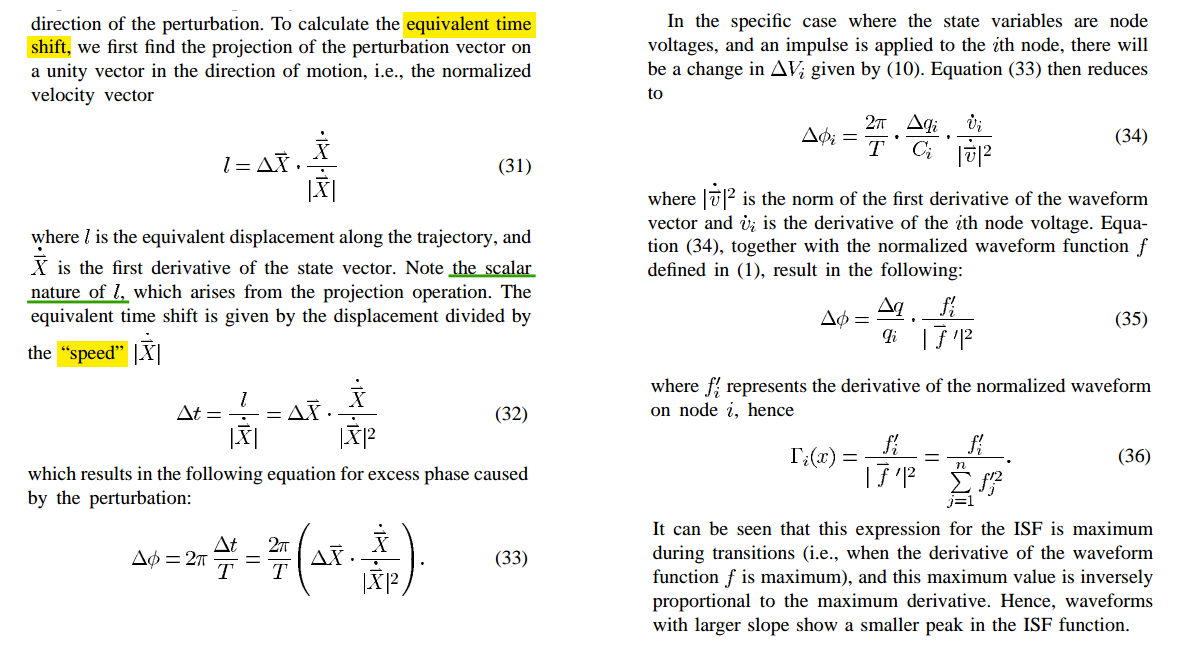
voltages, write \(\Delta \vec X = \sum_i
\Delta v_i\,\hat e_i\) (with \(\Delta
v_i = \Delta q_i/C_i\)) and the dot product
distributes: \[
\Delta\phi = \frac{2\pi}{T}\frac{\big(\sum_i \Delta v_i \hat
e_i\big)\cdot \dot{\vec X}}{\lVert\dot{\vec X}\rVert^{2}}
\;=\frac{2\pi}{T}\; \sum_i\,\frac{\Delta v_i\, \dot v_i}{\lVert\dot{\vec
X}\rVert^{2}} \;=\; \sum_i \Delta\phi_i,
\] For second-order system, one can use the normalized waveform
and its derivative as the state variables \[
\Gamma_{1}(x)=\frac{f'(x)}{f^{2}(x)+f'^{2}(x)} \qquad
\Gamma_{2}(x)=\frac{f''(x)}{f'^{2}(x)+f''^{2}(x)}
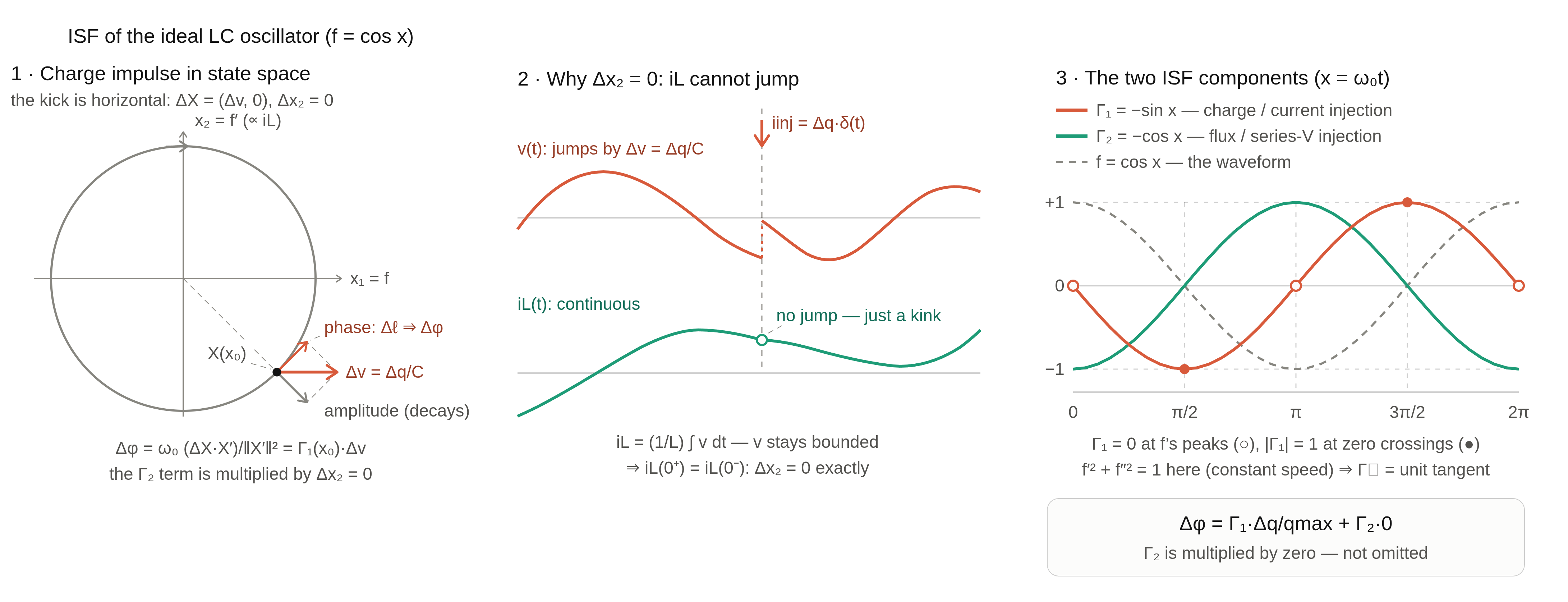
\] In the case of an ideal sinusoidal oscillator \(f=\cos(x)\) \[
\Gamma_{1}(x)=-\sin(x) \qquad \Gamma_{2}(x)=-\cos(x)
\] A finite charge impulse into the node cannot make the inductor
current jump (\(v\) stays bounded, so
\(i_L=\frac{1}{L}\int v\,dt\) is
continuous) — current component of the
perturbation is exactly zero. That's physics of
the input, not an approximation: \(\Delta\vec
X = (\Delta v,\,0)\) exactly, so \(\Gamma_2\) gets multiplied by zero
If the state variables are node
voltages, write \(\Delta \vec X = \sum_i
\Delta v_i\,\hat e_i\) (with \(\Delta
v_i = \Delta q_i/C_i\)) and the dot product
distributes: \[
\Delta\phi = \frac{2\pi}{T}\frac{\big(\sum_i \Delta v_i \hat
e_i\big)\cdot \dot{\vec X}}{\lVert\dot{\vec X}\rVert^{2}}
\;=\frac{2\pi}{T}\; \sum_i\,\frac{\Delta v_i\, \dot v_i}{\lVert\dot{\vec
X}\rVert^{2}} \;=\; \sum_i \Delta\phi_i,
\] For second-order system, one can use the normalized waveform
and its derivative as the state variables \[
\Gamma_{1}(x)=\frac{f'(x)}{f^{2}(x)+f'^{2}(x)} \qquad
\Gamma_{2}(x)=\frac{f''(x)}{f'^{2}(x)+f''^{2}(x)}
\] In the case of an ideal sinusoidal oscillator \(f=\cos(x)\) \[
\Gamma_{1}(x)=-\sin(x) \qquad \Gamma_{2}(x)=-\cos(x)
\] A finite charge impulse into the node cannot make the inductor
current jump (\(v\) stays bounded, so
\(i_L=\frac{1}{L}\int v\,dt\) is
continuous) — current component of the
perturbation is exactly zero. That's physics of
the input, not an approximation: \(\Delta\vec
X = (\Delta v,\,0)\) exactly, so \(\Gamma_2\) gets multiplied by zero
Total phase noise sums over physical sources, each weighted by its own ISF
- If every noise source in the circuit injects current into nodes — transistor channel noise, resistor noise, the usual on-chip situation — then the \(\Gamma_1\) family is the whole story with no approximation
- \(\Gamma_2\) enters only when a source physically acts as a series voltage on the inductor (flux injection), such as the coil's series resistance
quietly assumes the normal component contributes zero phase shift, i.e., that surfaces of equal phase (isochrons) cross the limit cycle orthogonally
Real oscillators violate this to varying degrees (amplitude-to-phase conversion), which is why the paper ranks direct impulse-injection simulation as the most accurate
The dot product and norm in (31)–(33) mean different things in different coordinates, so the same physical oscillator run through (33) in two different coordinate systems yields two different ISFs — and only one coordinate choice yields the paper's intended answer
Consider the ideal parallel LC network — pure sinusoid wave
Suppose a current pulse with area \(q\) suddenly changes the charge across the capacitor, its voltage changes by \(\Delta v_c=\Delta q/C\)
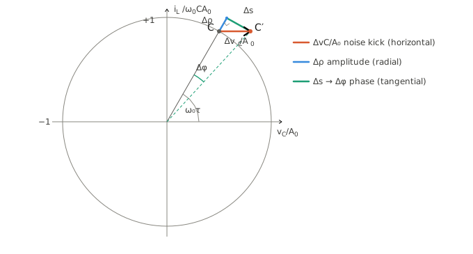
Decompose the horizontal kick \(\Delta\vec r=(\Delta x,0)\) and \(\Delta x=\Delta v_C/A_0\), with tangential direction \(\hat t=(-\sin\theta,\cos\theta)\) and radial direction \(\hat r=(\cos\theta,\sin\theta)\) \[ \Delta \phi = \arctan\left(\frac{\Delta\vec r\cdot \hat t}{1 + \Delta\vec r\cdot \hat r}\right) = \arctan\left(\frac{-\Delta x \sin \theta}{1 + \Delta x \cos \theta}\right)\approx -\frac{\Delta v_C}{A_0} \sin(\omega_0 \tau) \]
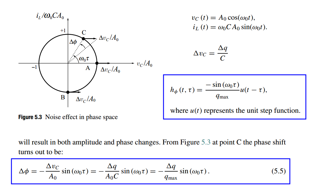
Therefore, the ISF of an ideal parallel LC resonator can be expressed as \(\boxed{\Gamma(\omega \tau)=-\sin(\omega_0 \tau)}\), which is independent of peak voltage value \(A_0\)
C. Calculation of ISF Based on the First Derivative
additive voltage error
A fixed \(\Delta V\) at a crossing shifts the crossing time by \(\Delta t = \Delta V/\dot v\), so \(\Delta\phi = \omega_0\Delta V/\dot v\). Express this against the normalized injection \(\Delta\phi = \Gamma\cdot\Delta V/V_{\max}\) and solve: \[ \Gamma_{\text{crossing}} = \frac{\omega_0 V_{\max}}{\dot v} = \frac{1}{f'} \] Now take eq. (37) at the mid-transition, where \(f'' = 0\) (inflection point): \[ \Gamma = \frac{f'}{f'^2 + f''^2}\;\Big|_{f''=0} = \frac{f'}{f'^2} = \frac{1}{f'} \]
\[ \boxed{ \text{steeper transition} \quad\Longrightarrow\quad \text{smaller ISF peak} } \] with \(\Gamma = \sin x\), at crossing \(\sin x =1\), which is derivative of edge \[ \Delta \phi = \Gamma \frac{\Delta q}{q_\text{max}} = \sin x\cdot \frac{\Delta q}{C\cdot A}= \sin x\cdot \frac{\Delta q}{C\cdot A\sin x} \]
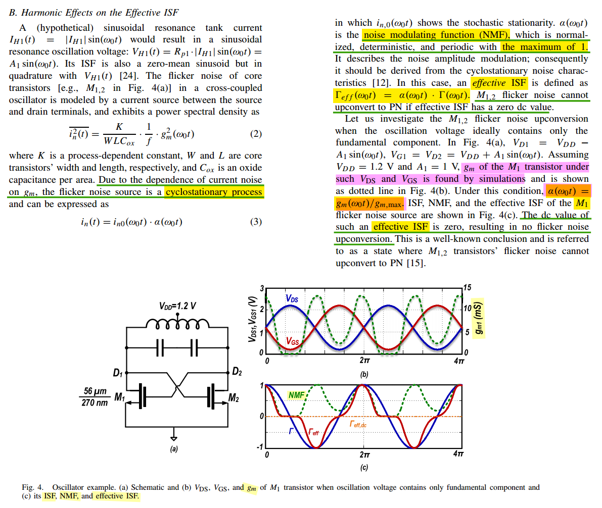
Effective ISF
cyclostationary noise sources
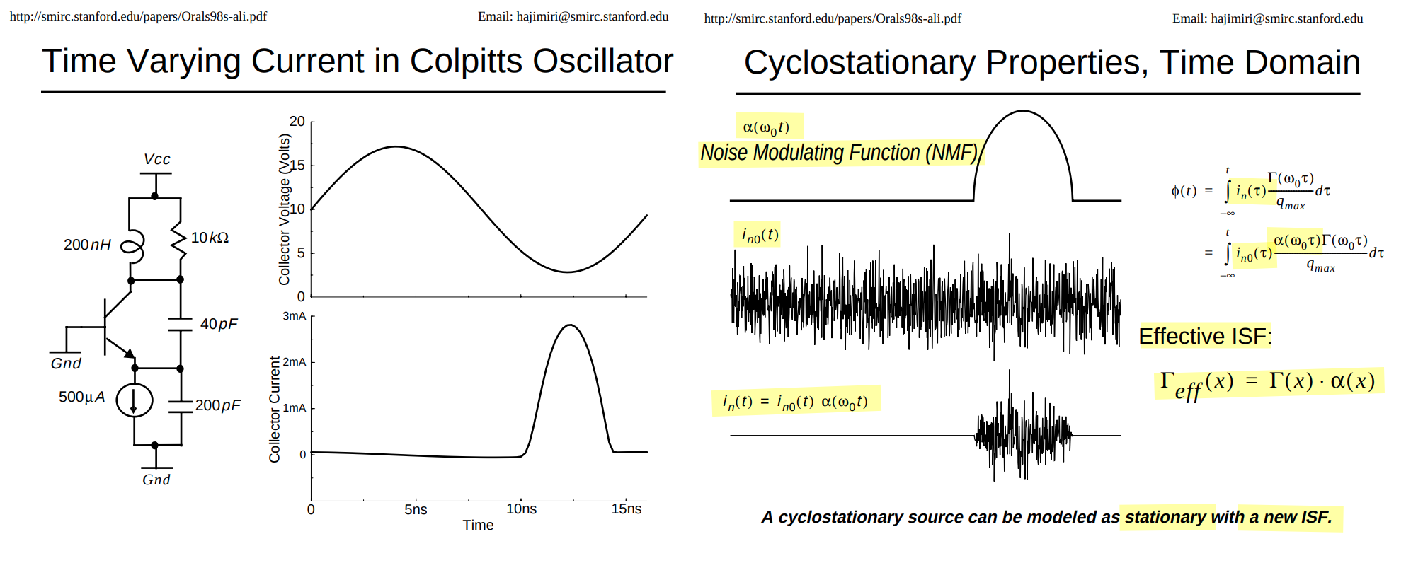
Cyclostationary noise can be viewed as stationary noise, \(i_{n0}(t)\), multiplied by a periodic envelope, \(\alpha(\omega_0 t)\).
Effective ISF — ISF multiplied with Noise Modulating Function (NMF)
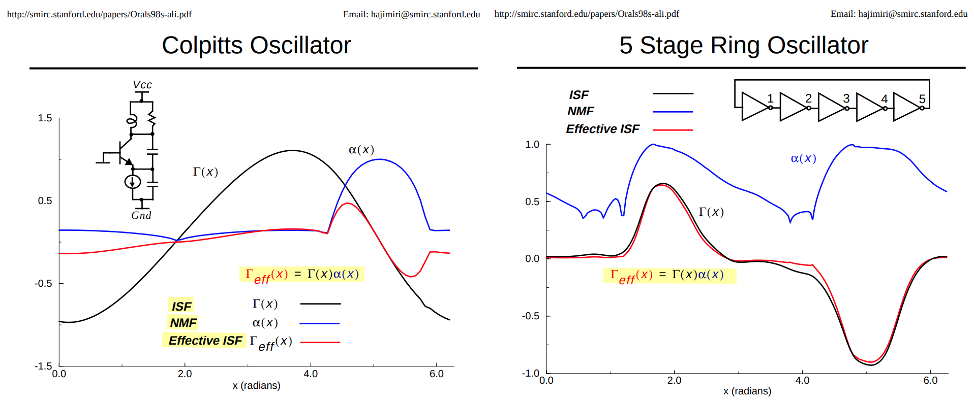
For Colpitts Oscillator, \(\Gamma_\text{eff}(x)\) is different from \(\Gamma(x)\), however \(\Gamma_\text{eff}(x)\) and \(\Gamma(x)\) are almost identical for ring oscillator
thermal noise with NMF
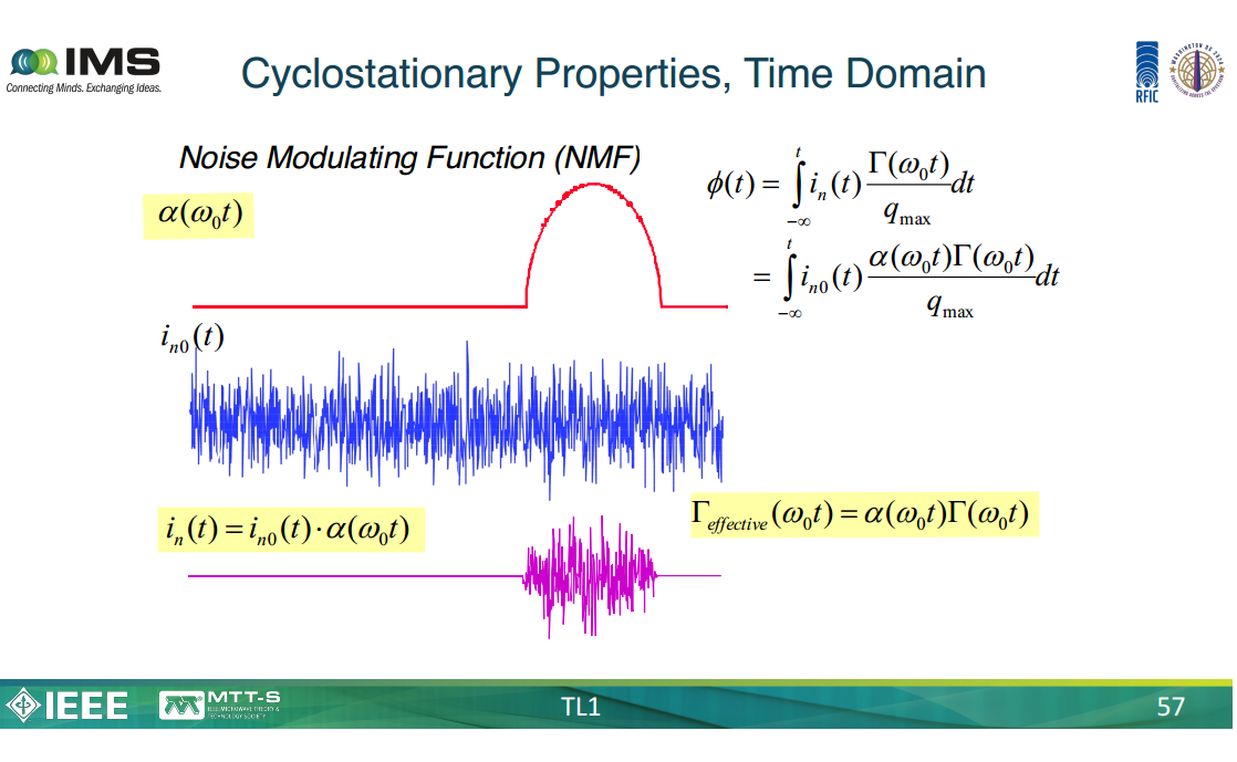
source-specific ISF + its NMF
flicker noise with effective non-normalized ISF
Y. Hu, T. Siriburanon and R. B. Staszewski, "A Low-Flicker-Noise 30-GHz Class-F23 Oscillator in 28-nm CMOS Using Implicit Resonance and Explicit Common-Mode Return Path," in IEEE Journal of Solid-State Circuits, vol. 53, no. 7, pp. 1977-1987, July 2018 [https://ieeexplore.ieee.org/stamp/stamp.jsp?tp=&arnumber=8345650]
—, "Oscillator Flicker Phase Noise: A Tutorial," in IEEE Transactions on Circuits and Systems II: Express Briefs, vol. 68, no. 2, pp. 538-544, Feb. 2021 [paper] [slides]
—, "Intuitive Understanding of Flicker Noise Reduction via Narrowing of Conduction Angle in Voltage-Biased Oscillators," in IEEE Transactions on Circuits and Systems II: Express Briefs, vol. 66, no. 12, pp. 1962-1966, Dec. 2019 [https://sci-hub.jp/10.1109/TCSII.2019.2896483]
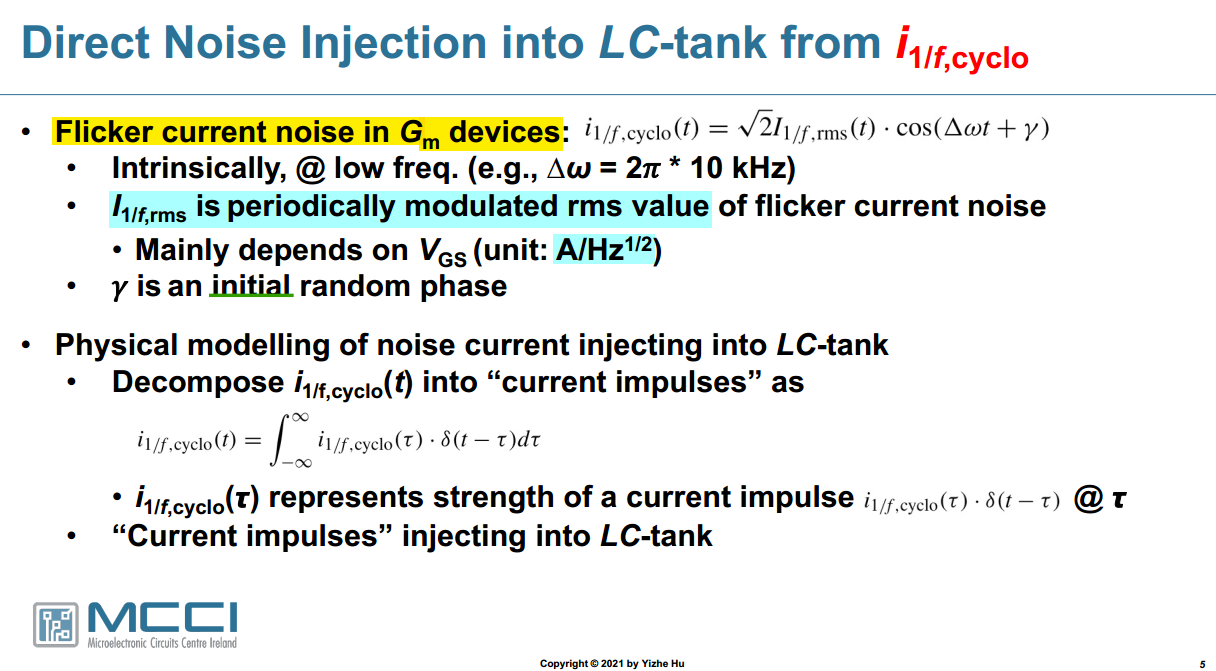
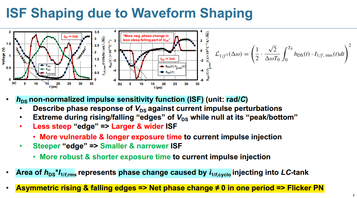
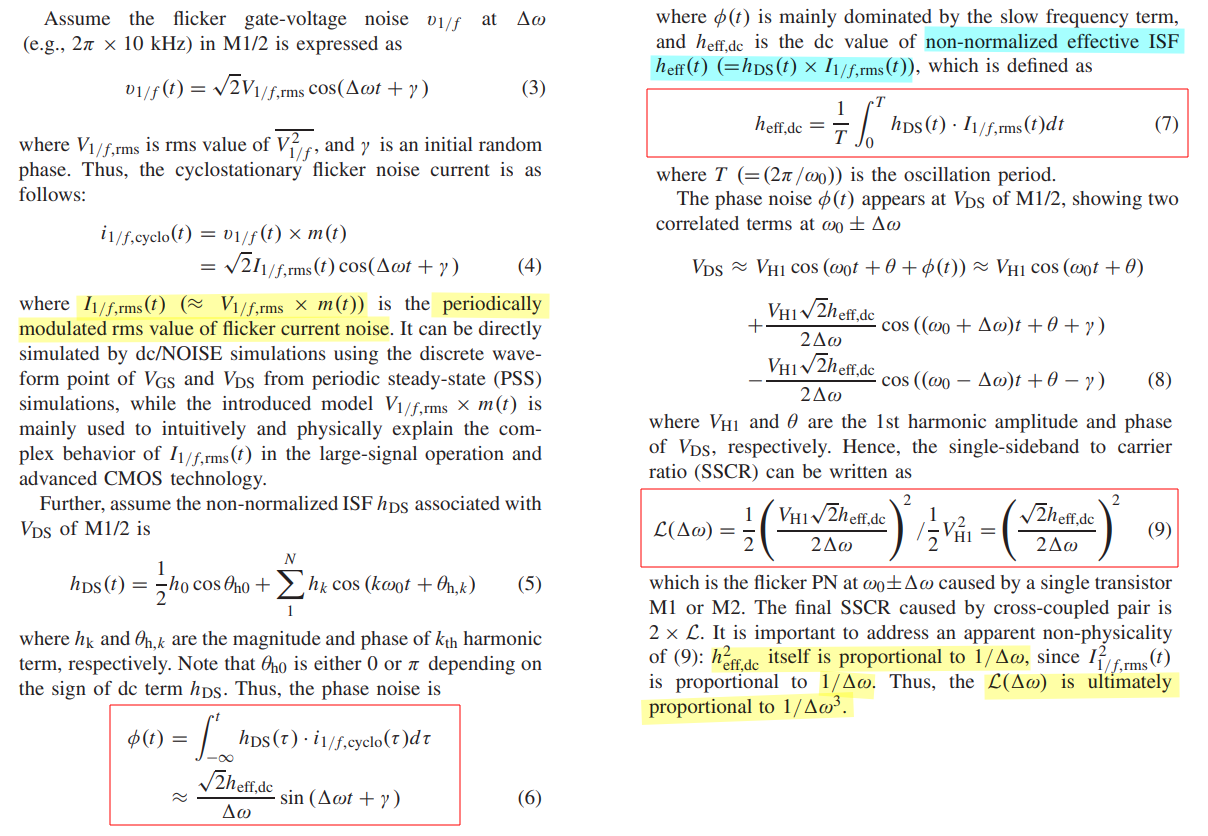
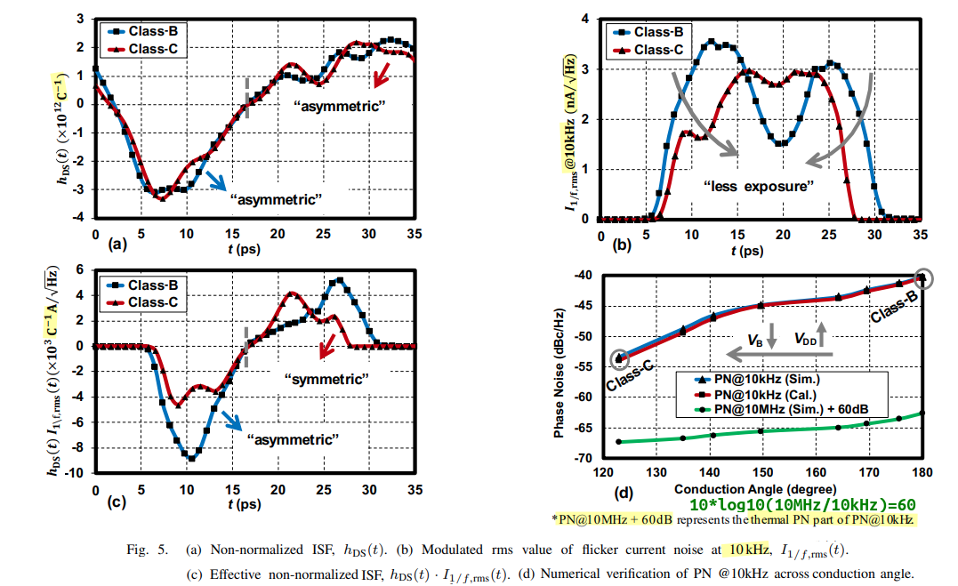
With the paper’s implicit \(1\text{-Hz}\) noise bandwidth, Eq. (3) \[ v_{1/f}(t) = \sqrt{2}\,V_{1/f,\mathrm{rms}} \cos(\Delta\omega t+\gamma) \] represents one narrowband sinusoidal noise component.
Here: \[ V_{1/f,\mathrm{rms}} = \sqrt{S_{v,1/f}(\Delta f)\cdot 1\,\mathrm{Hz}} \] is the RMS voltage amplitude of that component. Therefore, strictly within Eq. (3), \[ [V_{1/f,\mathrm{rms}}]=\mathrm V. \] Because the bandwidth is implicitly \(1\,\mathrm{Hz}\), its numerical value equals the amplitude spectral density expressed in \(\mathrm{V}/\sqrt{\mathrm{Hz}}\): \[ V_{1/f,\mathrm{rms}}[\mathrm V] \overset{B=1\,\mathrm{Hz}}{=} \sqrt{S_{v,1/f}} \left[\frac{\mathrm V}{\sqrt{\mathrm{Hz}}}\right] \sqrt{1\,\mathrm{Hz}}. \] Also, more precisely:
- \(\Delta\omega t+\gamma\) is the phase of the sinusoidal component.
- \(\cos(\Delta\omega t+\gamma)\) is the dimensionless sinusoidal waveform.
- \(\gamma\) is the random initial phase.
- \(\sqrt{2}V_{1/f,\mathrm{rms}}\) is the peak amplitude.
Indeed, \[ \operatorname{rms} \left\{ \sqrt{2}V_{1/f,\mathrm{rms}} \cos(\Delta\omega t+\gamma) \right\} = V_{1/f,\mathrm{rms}}. \] Therefore, the same interpretation applies to Eq. (4): \[ i_{1/f,\mathrm{cyclo}}(t) = \sqrt{2}I_{1/f,\mathrm{rms}}(t) \cos(\Delta\omega t+\gamma). \] Under the implicit \(1\text{-Hz}\) bandwidth, \[ [I_{1/f,\mathrm{rms}}(t)]=\mathrm A, \] From Eq. (4), \[ i_{1/f,\mathrm{cyclo}}(t) = \sqrt{2}\,I_{1/f,\mathrm{rms}}(t) \cos(\Delta\omega t+\gamma). \] Substitute this into the phase perturbation integral: \[ \begin{aligned} \phi(t) &= \int_{-\infty}^{t} h_{\mathrm{DS}}(\tau) i_{1/f,\mathrm{cyclo}}(\tau)\,d\tau \\ &= \sqrt{2} \int_{-\infty}^{t} h_{\mathrm{DS}}(\tau) I_{1/f,\mathrm{rms}}(\tau) \cos(\Delta\omega\tau+\gamma)\,d\tau. \end{aligned} \] Define the periodically varying effective ISF as \[ \color{blue}\boxed{h_{\mathrm{eff}}(t) \equiv h_{\mathrm{DS}}(t)I_{1/f,\mathrm{rms}}(t)} \] Therefore, \[ \phi(t) = \sqrt{2} \int_{-\infty}^{t} h_{\mathrm{eff}}(\tau) \cos(\Delta\omega\tau+\gamma)\,d\tau. \] Since \(h_{\mathrm{eff}}(t)\) is periodic with period \(T=2\pi/\omega_0\), write \[ h_{\mathrm{eff}}(t) = h_{\mathrm{eff,dc}} + \sum_{k=1}^{\infty} H_k\cos(k\omega_0t+\psi_k), \] where \[ h_{\mathrm{eff,dc}} = \frac{1}{T} \int_0^T h_{\mathrm{eff}}(t)\,dt = \frac{1}{T} \int_0^T h_{\mathrm{DS}}(t) I_{1/f,\mathrm{rms}}(t)\,dt. \] This is Eq. (7).
Substitution gives \[ \begin{aligned} \phi(t) ={}& \sqrt{2}h_{\mathrm{eff,dc}} \int^t\cos(\Delta\omega\tau+\gamma)\,d\tau \\ &+ \sqrt{2}\sum_{k=1}^{\infty}H_k \int^t \cos(k\omega_0\tau+\psi_k) \cos(\Delta\omega\tau+\gamma)\,d\tau. \end{aligned} \] The first term is \[ \sqrt{2}h_{\mathrm{eff,dc}} \int^t\cos(\Delta\omega\tau+\gamma)\,d\tau = \frac{\sqrt{2}h_{\mathrm{eff,dc}}}{\Delta\omega} \sin(\Delta\omega t+\gamma). \] For the harmonic terms, use \[ \cos A\cos B = \frac{1}{2}\left[\cos(A+B)+\cos(A-B)\right]. \] Thus, the exact harmonic contribution is \[ \begin{aligned} \phi_k(t) = \frac{\sqrt{2}H_k}{2} \Bigg[ & \frac{ \sin\!\left[(k\omega_0+\Delta\omega)t+\psi_k+\gamma\right] }{ k\omega_0+\Delta\omega } \\ +& \frac{ \sin\!\left[(k\omega_0-\Delta\omega)t+\psi_k-\gamma\right] }{ k\omega_0-\Delta\omega } \Bigg]. \end{aligned} \] These terms lie near \(k\omega_0\pm\Delta\omega\), whereas the DC term produces a slowly varying phase component directly at \(\Delta\omega\).
Because \[ \Delta\omega\ll\omega_0, \] the slow component is also much larger after integration: \[ \frac{1}{\Delta\omega} \gg \frac{1}{k\omega_0\pm\Delta\omega}. \] Therefore, keeping only the dominant low-frequency phase term, \[ \color{blue}\boxed{ \phi(t) \approx \frac{\sqrt{2}h_{\mathrm{eff,dc}}}{\Delta\omega} \sin(\Delta\omega t+\gamma) } \] The essential mechanism is \[ \underbrace{h_{\mathrm{DS}}(t)}_{\text{periodic ISF}} \, \underbrace{I_{1/f,\mathrm{rms}}(t)}_{\text{periodic noise amplitude}} \longrightarrow \underbrace{h_{\mathrm{eff,dc}}}_{\text{nonzero average}}, \]
M. Shahmohammadi, M. Babaie and R. B. Staszewski, "A 1/f Noise Upconversion Reduction Technique for Voltage-Biased RF CMOS Oscillators," in IEEE Journal of Solid-State Circuits, vol. 51, no. 11, pp. 2610-2624, Nov. 2016 [https://pure.tudelft.nl/ws/portalfiles/portal/30880387/07571191.pdf]
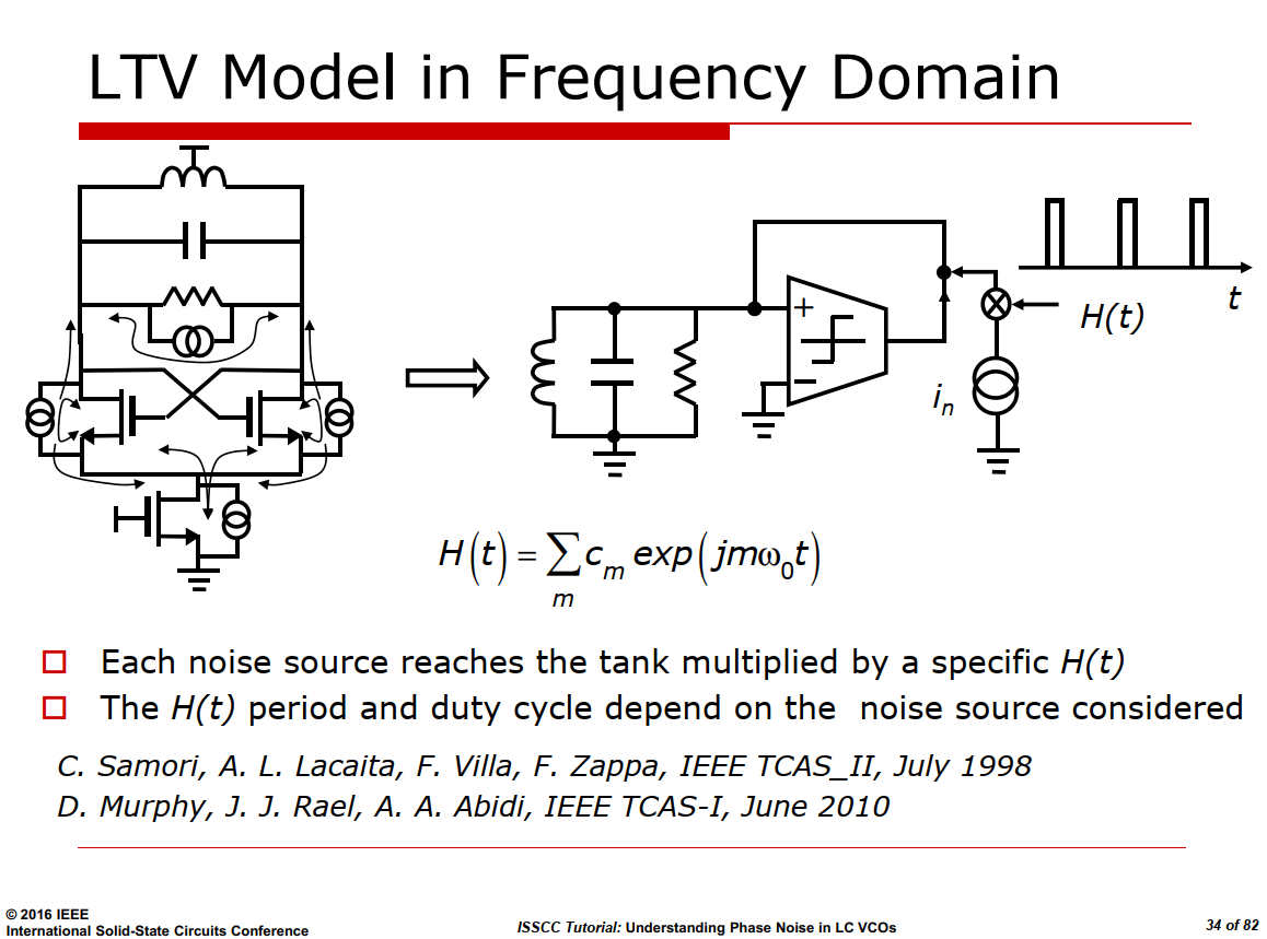
Murphy's Model — LTV in Frequency Domain
C. Samori, A. L. Lacaita, F. Villa and F. Zappa, "Spectrum folding and phase noise in LC tuned oscillators," in IEEE Transactions on Circuits and Systems II: Analog and Digital Signal Processing, vol. 45, no. 7, pp. 781-790, July 1998 [https://sci-hub.ru/10.1109/82.700925]
D. Murphy, J. J. Rael and A. A. Abidi, "Phase Noise in LC Oscillators: A Phasor-Based Analysis of a General Result and of Loaded Q ," in IEEE Transactions on Circuits and Systems I: Regular Papers, vol. 57, no. 6, pp. 1187-1203, June 2010 [https://sci-hub.ru/10.1109/TCSI.2009.2030110]
The differential pair plays two distinct roles. Toward its own noise it acts as a sampling gate — each transistor contributes only within the short conduction windows at the zero crossings — and the resulting injection is almost purely phase-modulating.
Toward the tail noise it acts as a single-balanced mixer, commutating the upstream current with a square wave and folding it as a single sideband that splits equally into AM and PM
Diff. Pair Noise
For diff. pair noise, the diff. pair is its own noise gate
half of the noise current of each generator reaches the tank, while the remaining half circulates within the transistor
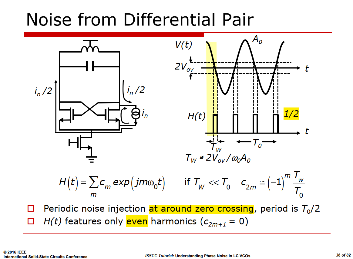
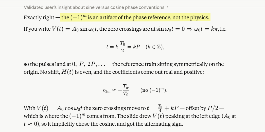
A reference pulse train centered at \(t=0\) would have plain positive
coefficients (\(\tfrac{T_w}{T_0}\),
with \(\operatorname{sinc} \approx
1\)). \[
c_n = \frac{1}{2}\cdot
\frac{T_w}{T_0/2}\operatorname{sinc}\left(\frac{nT_w}{T_0/2}\right)=\frac{T_w}{T_0}\operatorname{sinc}\left(\frac{2nT_w}{T_0}\right)
\] The real injection sits at \(t=T_0/4\), and since the pulse-train period
is \(P=T_0/2\), that offset is exactly
\(P/2\) — a half-period shift. Every
coefficient therefore picks up \((-1)^m\) — \(e^{j2m\omega_0\cdot T_0/4}=e^{jm\pi}\)
\[
c_{2m} = \underbrace{(-1)^m}_{\text{position}}\,
\underbrace{\frac{T_w}{T_0}}_{\text{area / period}}\,
\underbrace{\operatorname{sinc}\!\left(\frac{2mT_w}{T_0}\right)}_{\to\,1
\text{ as } T_w \ll T_0}
\] 
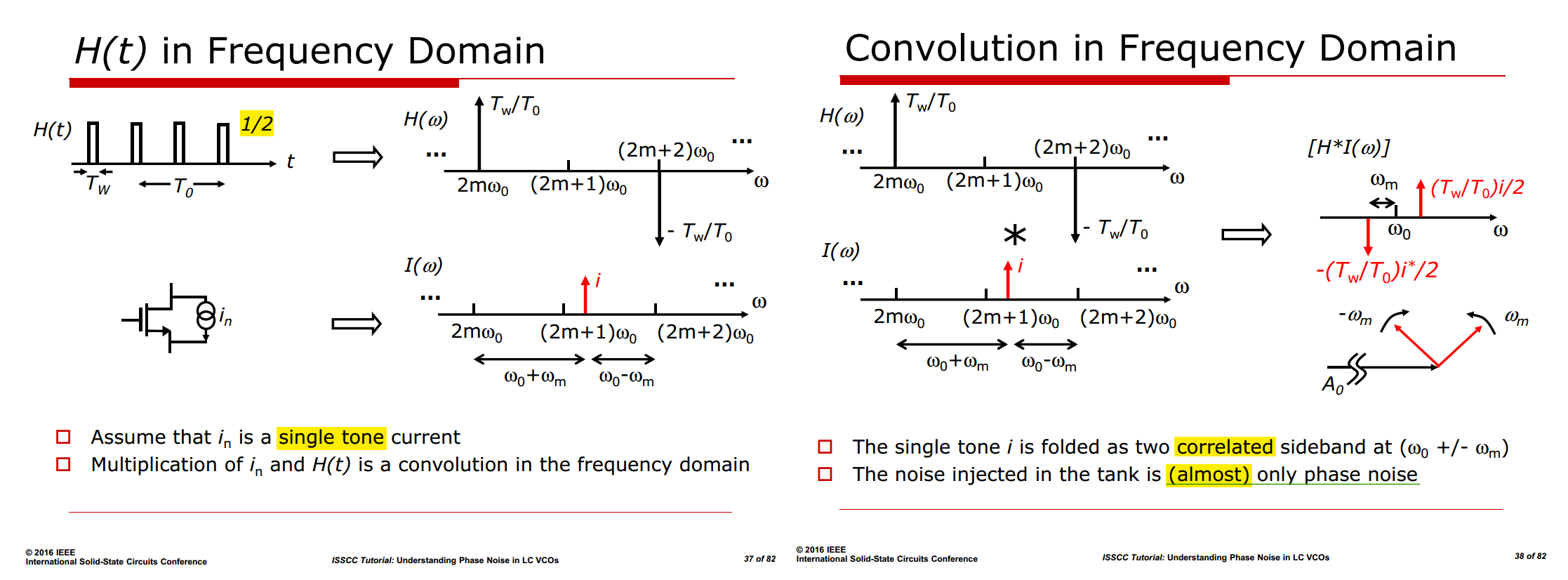
Consequently, excess noise arises solely from the components at \(\omega_0\pm \omega_m\), since all other spectral components lie outside the tank bandwidth and are therefore suppressed by the resonator's frequency-selective filtering
With Cyclostationary Noise (Modulated Noise) [https://raytroop.github.io/2024/04/27/noise/#cyclostationary-noise-modulated-noise]
For one MOS, Two-Sided PSD is \[
S_O = S_I \cdot \mathcal{D}\cdot \mathcal{h}^2 = 2kT\gamma g_m\cdot
\frac{2T_W}{T_0}\cdot\frac{1}{4} = \frac{T_W}{2T_0}\cdot 2kT\gamma g_m
\] yield One-Sided PSD of one
MOS \[
S_O' = \textcolor{blue}{\frac{T_W}{2T_0}}\cdot 4kT\gamma g_m
\] 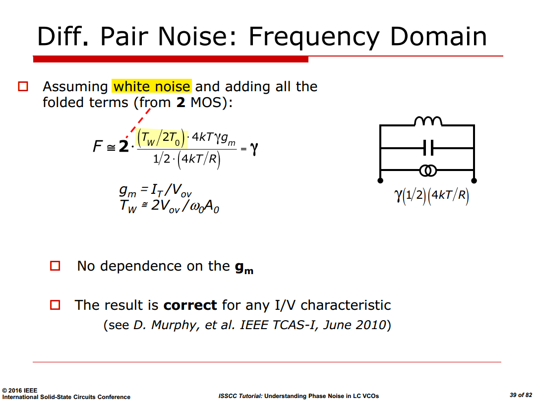
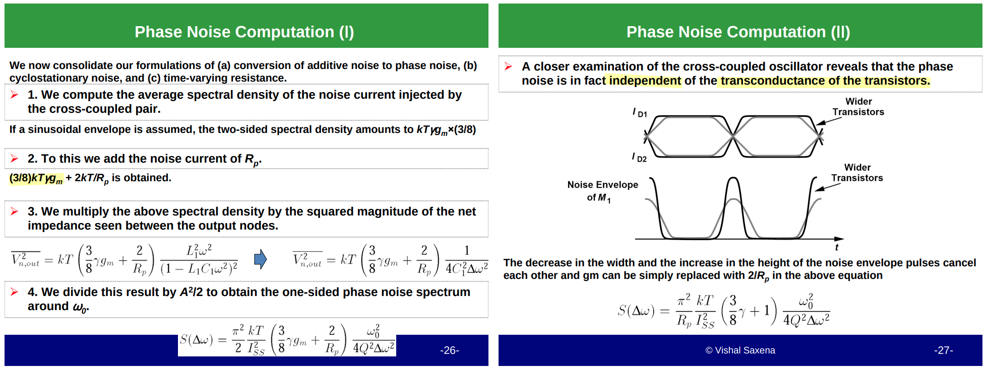
The single-tone analysis establishes that the differential-pair current is injected as almost pure phase noise, while summing the white-noise power over all harmonics of the gating function (\(\overline{H^2}=T_W/2T_0\)) sets its magnitude; together these yield the differential-pair contribution to the oscillator phase noise.
phase noise is independent of the transconductance of the transistors
Tail Noise
For the tail noise, the diff. pair is a mixer
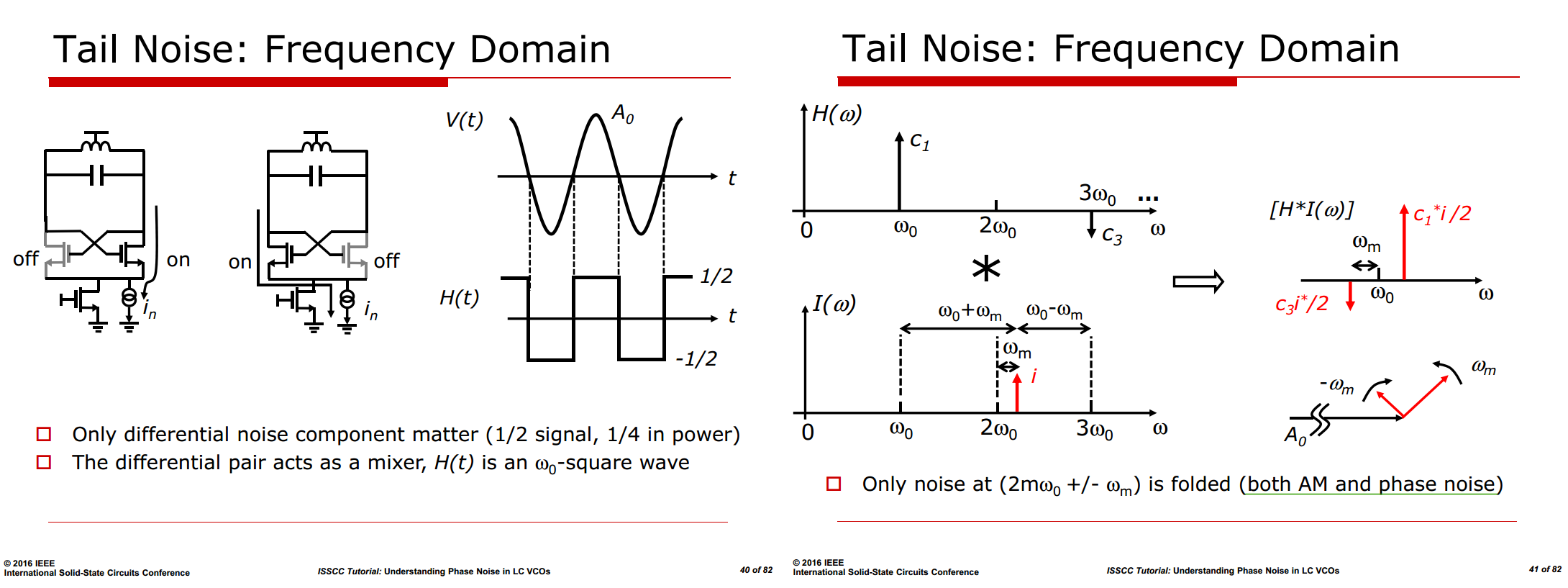 \[
V_{AM} = \tfrac{1}{2}\big(C_+ + \overline{C}_-\big) =
\tfrac{1}{2}\Big(\tfrac{c_1^* i}{2} + \tfrac{c_3^* i}{2}\Big)\qquad
V_{PM} = \tfrac{1}{2}\big(C_+ - \overline{C}_-\big) =
\tfrac{1}{2}\Big(\tfrac{c_1^* i}{2} - \tfrac{c_3^* i}{2}\Big)
\] \(V_{AM}\approx V_{PM}\) for
a square wave \(|c_1|=3|c_3|\) —
modulated tail noise is divided into AM and phase noise
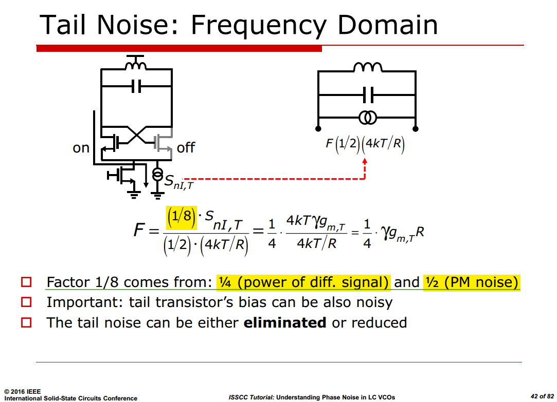
almost equally \[
S_{I,PN} = S_{nI,T} \cdot \mathcal{D}\cdot \mathcal{h}^2 \cdot
\frac{1}{2} = S_{nI,T} \cdot 1 \cdot \frac{1}{4}\cdot \frac{1}{2} =
\boxed{\frac{1}{8}\cdot S_{nI,T}}
\] The commutation folds tail noise as a (near) single
sideband, which is equivalent to equal AM and PM — and only the
PM half counts toward phase noise
\[
V_{AM} = \tfrac{1}{2}\big(C_+ + \overline{C}_-\big) =
\tfrac{1}{2}\Big(\tfrac{c_1^* i}{2} + \tfrac{c_3^* i}{2}\Big)\qquad
V_{PM} = \tfrac{1}{2}\big(C_+ - \overline{C}_-\big) =
\tfrac{1}{2}\Big(\tfrac{c_1^* i}{2} - \tfrac{c_3^* i}{2}\Big)
\] \(V_{AM}\approx V_{PM}\) for
a square wave \(|c_1|=3|c_3|\) —
modulated tail noise is divided into AM and phase noise
almost equally \[
S_{I,PN} = S_{nI,T} \cdot \mathcal{D}\cdot \mathcal{h}^2 \cdot
\frac{1}{2} = S_{nI,T} \cdot 1 \cdot \frac{1}{4}\cdot \frac{1}{2} =
\boxed{\frac{1}{8}\cdot S_{nI,T}}
\] The commutation folds tail noise as a (near) single
sideband, which is equivalent to equal AM and PM — and only the
PM half counts toward phase noise
Noise around \(\boxed{2\omega_0 \pm\omega_m}\) dominate phase noise due to \(|c_1|, |c_3| \gg |c_{2m+1}| \space\space\space\space \forall m>1\)
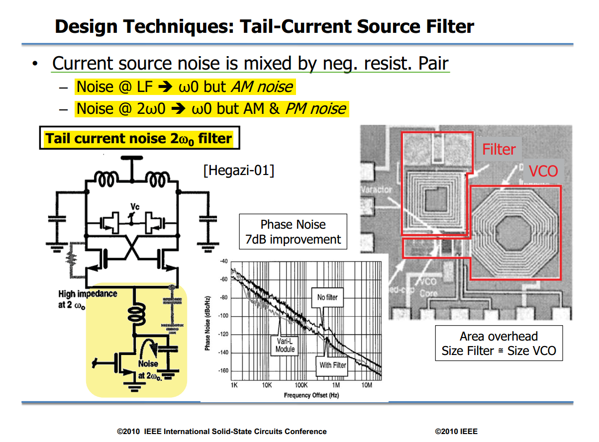
E. Hegazi, H. Sjoland and A. Abidi, "A filtering technique to lower oscillator phase noise," 2001 IEEE International Solid-State Circuits Conference. Digest of Technical Papers. ISSCC (Cat. No.01CH37177), San Francisco, CA, USA, 2001 [paper, slides]
Peter Kinget, ISSCC 2010 short course, Transistor-Level Design of Critical PLL Circuits
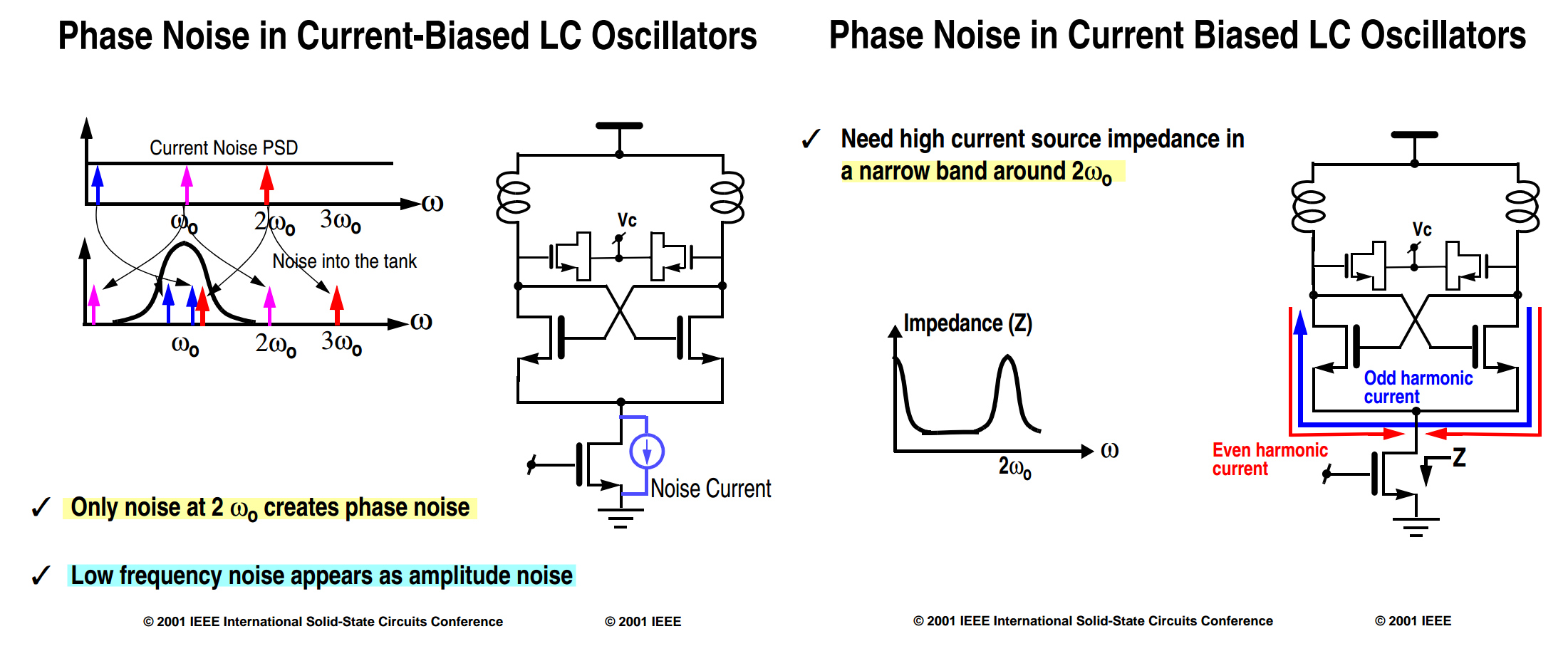
In the first-order, noise around DC (flicker) is upconverted as a pair of correlated, symmetric sidebands around the carrier — which is pure AM
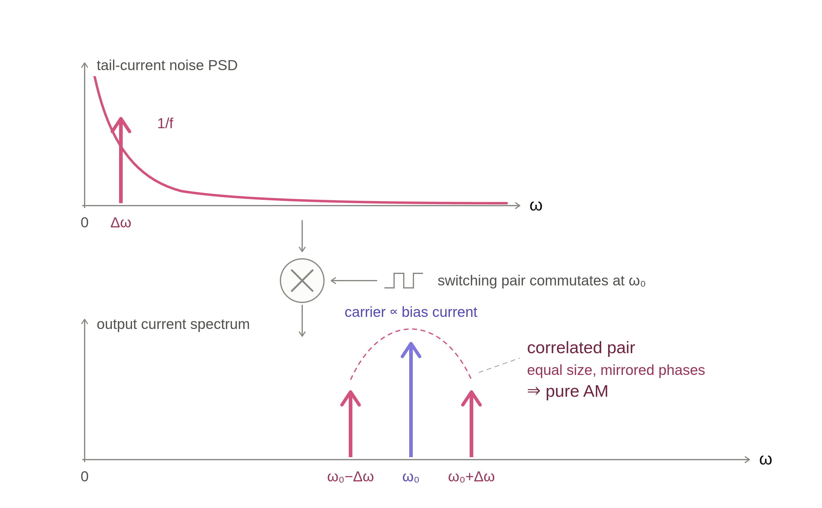
J. J. Rael and A. A. Abidi, "Physical processes of phase noise in differential LC oscillators," IEEE Custom Integrated Circuits Conference (CICC), 2000 [https://people.engr.tamu.edu/spalermo/ecen620/physical_processes_pn_diff_lc_osc_rael_cicc_2000.pdf]
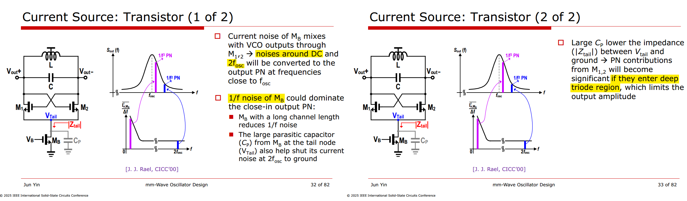
practical outcome once second-order conversion effects are included
- flicker near DC → AM/bias modulation → converted to FM → 1/f3 PN (the purple arrow in its spectrum)
- while thermal noise at 2fosc → direct PN → 1/f2 PN (the blue arrow)
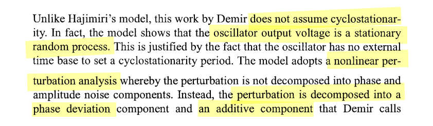
Demir's Model — NLTV
A. Demir, A. Mehrotra and J. Roychowdhury, "Phase noise in oscillators: a unifying theory and numerical methods for characterization," in IEEE Transactions on Circuits and Systems I: Fundamental Theory and Applications, vol. 47, no. 5, pp. 655-674, May 2000 [https://sci-hub.jp/10.1109/81.847872]
A. Demir and A. Sangiovanni-Vincentelli, Analysis and Simulation of Noise in Nonlinear Electronic Circuits and Systems, vol. 425. Boston, MA, USA: Kluwer Academic Publishers, 1998
A. Mehrotra and A. Sangiovanni-Vincentelli, Noise Analysis of Radio Frequency Circuits, 1st ed. New York, NY, USA: Springer, 2004
Demir's theory is essentially Floquet theory applied to the limit cycle of an autonomous oscillator, and the PPV is one specific Floquet vector
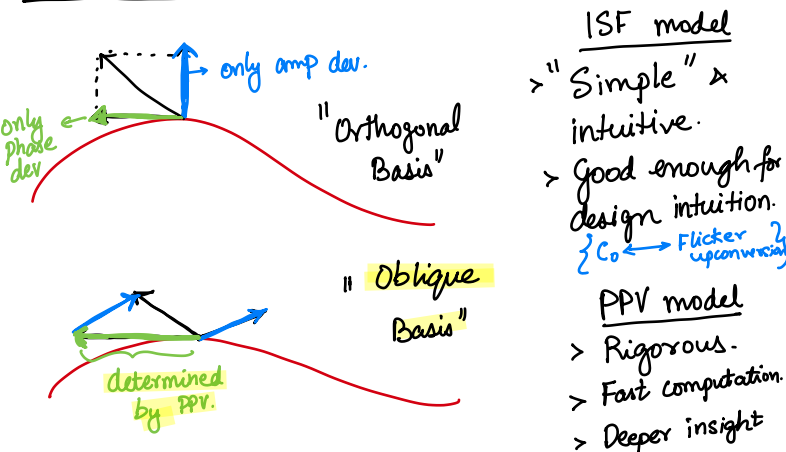
PPV (Perturbation Projection Vector)
A. Demir and J. Roychowdhury, "A reliable and efficient procedure for oscillator PPV computation, with phase noise macromodeling applications," in IEEE Transactions on Computer-Aided Design of Integrated Circuits and Systems, vol. 22, no. 2, pp. 188-197, Feb. 2003 [https://sci-hub.se/10.1109/TCAD.2002.806599]
Helene Thibieroz, Customer Support CIC. Using Spectre RF Noise-Aware PLL Methodology to Predict PLL Behavior Accurately [https://citeseerx.ist.psu.edu/document?repid=rep1&type=pdf&doi=3056e59ea76165373f90152f915a829d25dabebc]
Aditya Varma Muppala. Perturbation Projection Vector (PPV) Theory | Oscillators 11 | MMIC 16 [youtu.be, notes]
S. Levantino and P. Maffezzoni, "Computing the Perturbation Projection Vector of Oscillators via Frequency Domain Analysis," in IEEE Transactions on Computer-Aided Design of Integrated Circuits and Systems, vol. 31, no. 10, pp. 1499-1507, Oct. 2012 [https://sci-hub.se/10.1109/TCAD.2012.2194493]
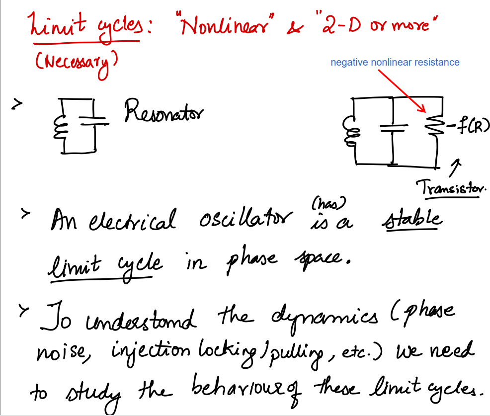
Limit Cycles
[https://adityamuppala.github.io/assets/Notes_YouTube/MMIC_Limit_Cycles.pdf]
Nonlinear Dynamics

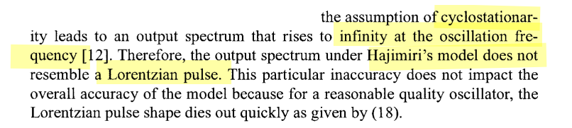
Lorentzian spectrum

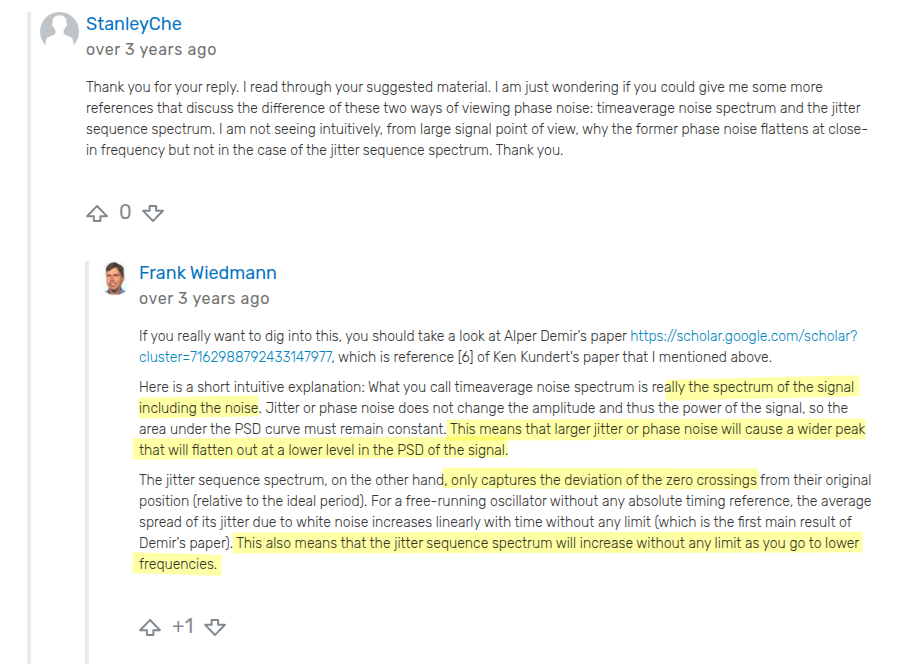
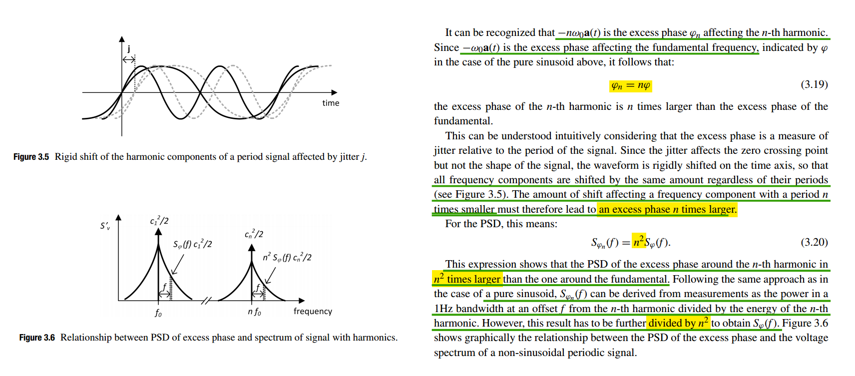
We typically use the two spectra, \(S_{\phi n}(f)\) and \(S_{out}(f)\), interchangeably, but we must resolve these inconsistencies. voltage spectrum is called Lorentzian spectrum
The periodic signal \(x(t)\) can be expanded in Fourier series as:

Assume that the signal is subject to excess phase noise, which is modeled by adding a time-dependent noise component \(\alpha(t)\). The noisy signal can be written \(x(t+\alpha(t))\), the added excess phase \(\phi(t)= \frac{\alpha(t)}{\omega_0}\)

The autocorrelation of the noisy signal is by definition:

The autocorrelation averaged over time results in:

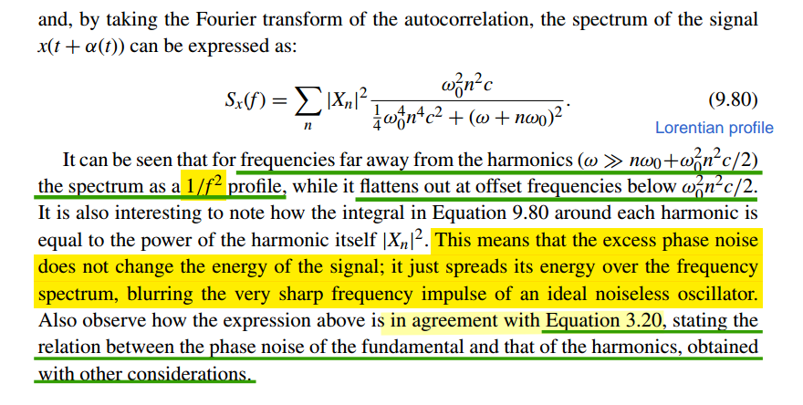
By taking the Fourier transform of the autocorrelation, the spectrum of the signal \(x(t + \alpha(t))\) can be expressed as

It is also interesting to note how the integral in Equation 9.80 around each harmonic is equal to the power of the harmonic itself \(|X_n|^2\)
The integral \(S_x(f)\) around harmonic is \[\begin{align} P_{x,n} &= \int_{f=-\infty}^{\infty} |X_n|^2\frac{\omega_0^2n^2c}{\frac{1}{4}\omega_0^4n^4c^2+(\omega +n\omega_0)^2}df = |X_n|^2\int_{\Delta f=-\infty}^{\infty}\frac{2\beta}{\beta^2+(2\pi\cdot\Delta f)^2}d\Delta f \\ &= |X_n|^2\frac{1}{\pi}\arctan(\frac{2\pi \Delta f}{\beta})|_{-\infty}^{\infty} = |X_n|^2 \end{align}\]
The phase noise does not affect the total power in the signal, it only affects its distribution
- Without phase noise, \(S_v(f)\) is a series of impulse functions at the harmonics of \(f_o\).
- With phase noise, the impulse functions spread, becoming fatter and shorter but retaining the same total power
Razavi's PN
Additive Noise to PN
\(n_I(t)\) and \(n_Q(t)\) have the same PSD and are uncorrelated
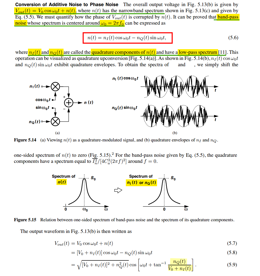
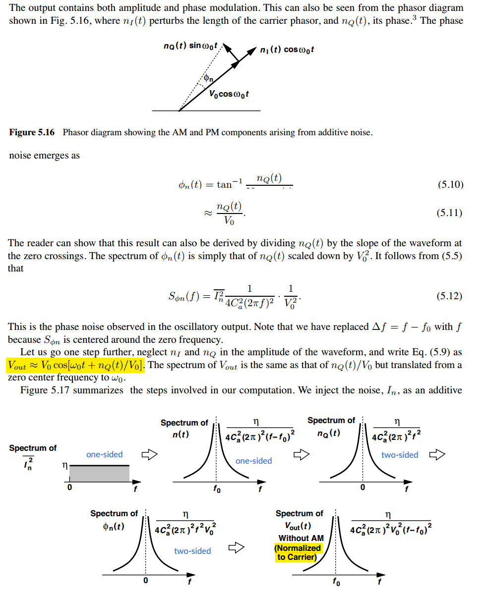
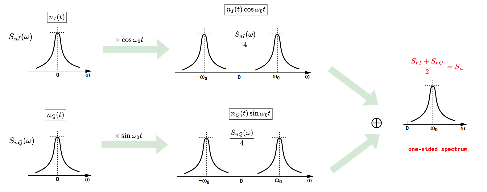
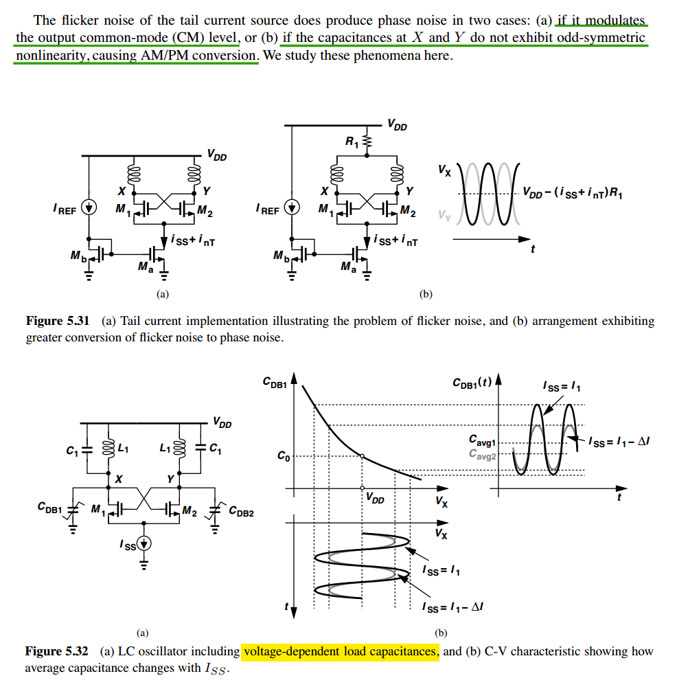
Tail Thermal Noise
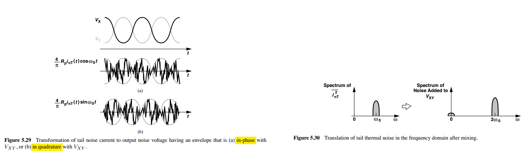
low-frequency content:

around \(\omega_0\):
no phase noise is produced

around \(2\omega_0\):
\(\frac{2}{\pi}[n_I(t)\cos2\omega_0 t - n_Q(t)\sin2\omega_0 t]\cdot \color{red}\cos\omega_0 t\) produce most phase noise
\(\frac{2}{\textcolor{green}{3}\pi}[n_I(t)\cos2\omega_0 t - n_Q(t)\sin2\omega_0 t]\cdot \color{red}\cos3\omega_0 t\) produce phase noise, but can be negligible — \(10\log(1+\frac{1}{3^2})\approx +0.46\, \text{dB}\)
Tail Flicker Noise
Abidi & Hooman's PN
A. A. Abidi and D. Murphy, "How to Design a Differential CMOS LC Oscillator," in IEEE Open Journal of the Solid-State Circuits Society, vol. 5, pp. 45-59, 2025 [https://ieeexplore.ieee.org/stamp/stamp.jsp?arnumber=10818782]
A. Mirzaei and A. A. Abidi, "The Spectrum of a Noisy Free-Running Oscillator Explained by Random Frequency Pulling," in IEEE Transactions on Circuits and Systems I: Regular Papers, vol. 57, no. 3, pp. 642-653, March 2010 [https://sci-hub.jp/10.1109/TCSI.2009.2024970]
J. J. Rael and A. A. Abidi, "Physical processes of phase noise in differential LC oscillators," IEEE Custom Integrated Circuits Conference (CICC), 2000 [https://people.engr.tamu.edu/spalermo/ecen620/physical_processes_pn_diff_lc_osc_rael_cicc_2000.pdf]
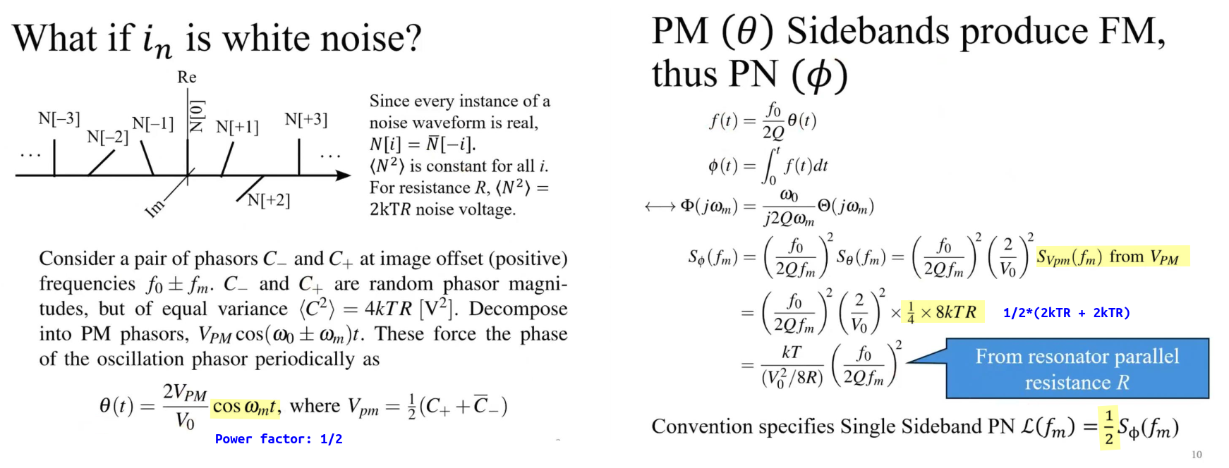
\[ V_{PM}\cos \omega_m t \overset{\text{power}}{\longrightarrow} \frac{S_{Vpm}}{2} = \frac{1}{2}(2kTR + 2kTR) \] quadrature noise → geometric tilt \(\phi,\, \Phi\) (bounded) → frequency shift \(f \propto \theta\) → accumulated phase \(\phi = \int f\,dt,\, \Theta\). Me

Noise Passing through a Nonlinearity
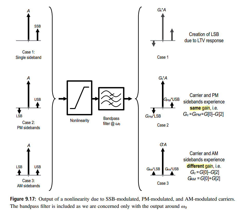
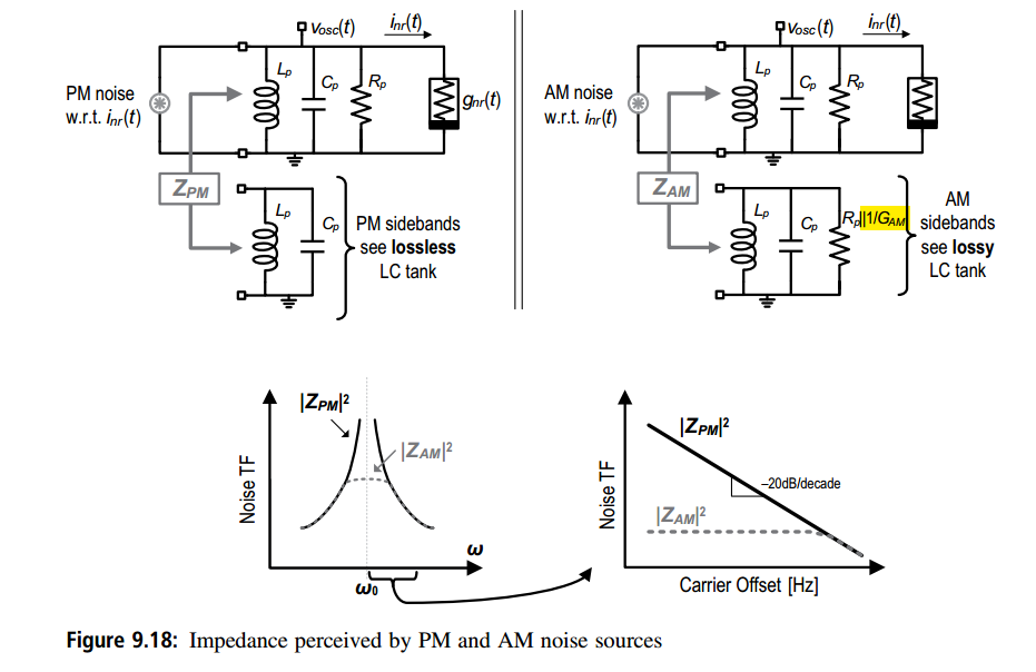
Bank's General Result
J. Bank, "A harmonic-oscillator design methodology based on describing functions," Ph.D. dissertation, Dept. Signals Syst., Sch. Elect. Eng., Chalmers Univ. Techn., Chalmers, Sweden, 2006. [https://publications.lib.chalmers.se/records/fulltext/17376.pdf]
A. Mazzanti and A. Bevilacqua, "On the Phase Noise Performance of Transformer-Based CMOS Differential-Pair Harmonic Oscillators," in IEEE Transactions on Circuits and Systems I: Regular Papers, vol. 62, no. 9, pp. 2334-2341, Sept. 2015 [https://sci-hub.jp/10.1109/TCSI.2015.2451915]
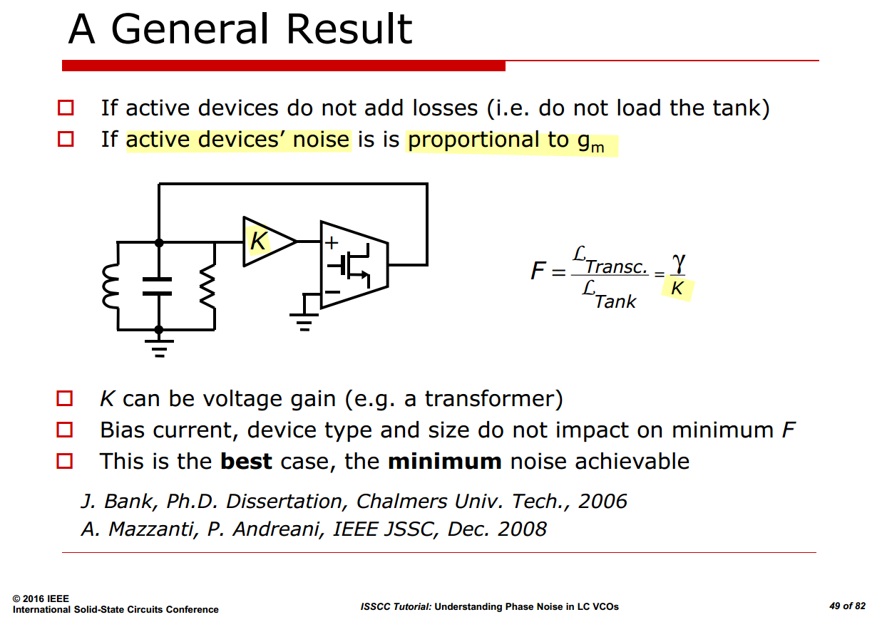
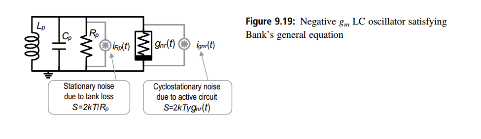

For the oscillation condition \(\overline{g_m}R_p=1\), the total noise-current power spectral density (PSD) is \[ \overline{i_n^2} = \overline{i_R^2} + \overline{i_{gnr}^2} = \frac{4kT}{R_p} + 4kT\gamma\overline{g_m} = \frac{4kT}{R_p}\left(1+\gamma\overline{g_m}R_p\right) = \frac{4kT}{R_p}(1+\gamma). \]
More generally, if \(K\overline{g_m}R_p=1\), then \(\overline{g_m}R_p=1/K\), and the PSD becomes \[ \overline{i_n^2} = \frac{4kT}{R_p}\left(1+\frac{\gamma}{K}\right). \]
Two-Port Oscillators
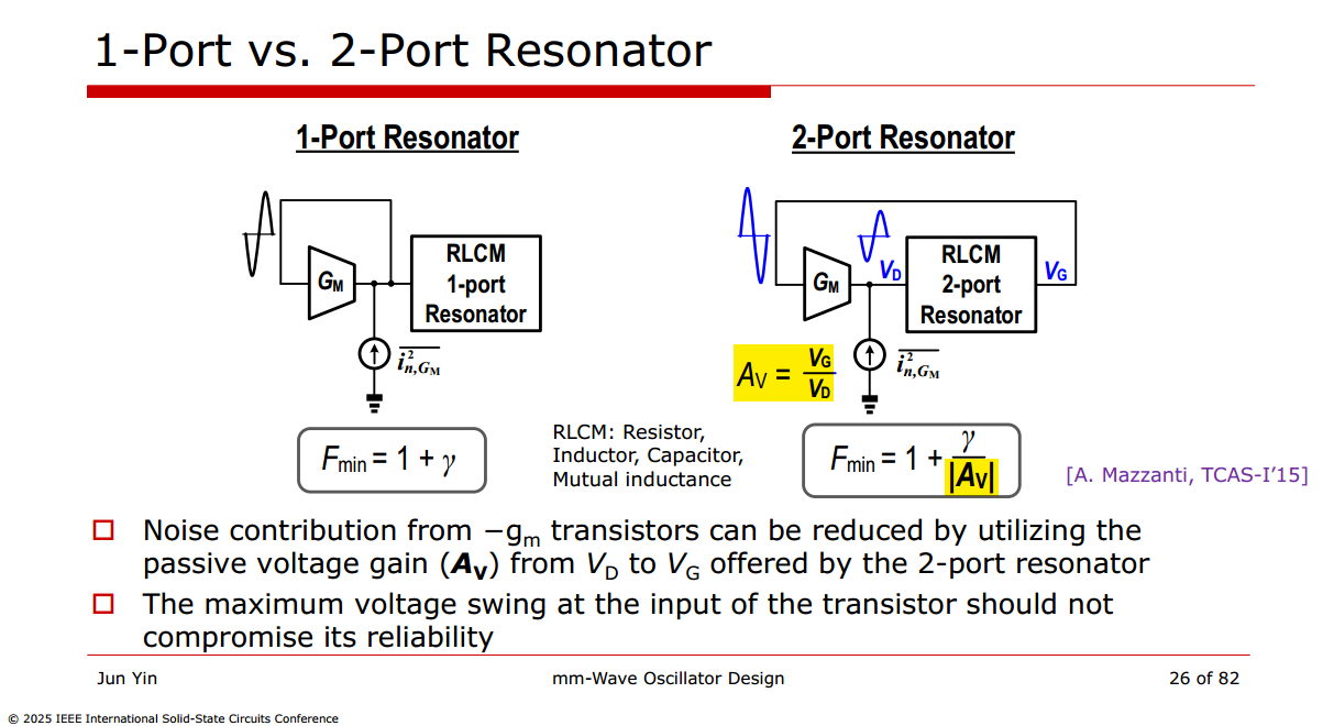
flicker noise upconversion
Y. Hu, T. Siriburanon and R. B. Staszewski, "Oscillator Flicker Phase Noise: A Tutorial," in IEEE Transactions on Circuits and Systems II: Express Briefs, vol. 68, no. 2, pp. 538-544, Feb. 2021 [paper] [slides]
—, "Intuitive Understanding of Flicker Noise Reduction via Narrowing of Conduction Angle in Voltage-Biased Oscillators," in IEEE Transactions on Circuits and Systems II: Express Briefs, vol. 66, no. 12, pp. 1962-1966, Dec. 2019 [https://sci-hub.jp/10.1109/TCSII.2019.2896483]
E. G. Ioannidis, C. G. Theodorou, T. A. Karatsori, S. Haendler, C. A. Dimitriadis and G. Ghibaudo, "Drain-Current Flicker Noise Modeling in nMOSFETs From a 14-nm FDSOI Technology," in IEEE Transactions on Electron Devices, vol. 62, no. 5, pp. 1574-1579, May 2015 [https://sci-hub.jp/10.1109/TED.2015.2411678]
Two different mechanisms: \[ \boxed{\text{tail-transistor }1/f\text{ noise}} \qquad\text{vs.}\qquad \boxed{\text{cross-coupled-pair }1/f\text{ noise}} \] They are not upconverted through exactly the same physical path
Tail-current-source flicker noise
J. J. Rael and A. A. Abidi, "Physical processes of phase noise in differential LC oscillators," Proceedings of the IEEE 2000 Custom Integrated Circuits Conference (Cat. No.00CH37044), Orlando, FL, USA, 2000 [https://people.engr.tamu.edu/spalermo/ecen620/physical_processes_pn_diff_lc_osc_rael_cicc_2000.pdf]
A. Bevilacqua and P. Andreani, "An Analysis of 1/f Noise to Phase Noise Conversion in CMOS Harmonic Oscillators," in IEEE Transactions on Circuits and Systems I: Regular Papers, vol. 59, no. 5, pp. 938-945, May 2012 [https://sci-hub.jp/10.1109/TCSI.2012.2190564]
\[ v_{n,\mathrm{tail}}^{1/f} \rightarrow \Delta I_T \rightarrow \text{AM and harmonic-content modulation} \rightarrow \Delta\omega_0 \rightarrow \phi(t). \]
They explicitly associate tail-current flicker noise with the sensitivity of oscillation frequency to tail current, \[ K_{I_T\rightarrow\omega} = \frac{\partial\omega_{\mathrm{osc}}}{\partial I_T}. \] Thus, \[ S_{\phi}(\Delta f) \approx \frac{ \left| \partial\omega_{\mathrm{osc}}/\partial I_T \right|^2 S_{I_T}(\Delta f)} {(2\pi\Delta f)^2}. \] For \(S_{I_T}\propto1/\Delta f\), this produces \(S_\phi\propto1/\Delta f^3\).
Cross-coupled-pair flicker noise
Y. Hu, T. Siriburanon and R. B. Staszewski, "A Low-Flicker-Noise 30-GHz Class-F23 Oscillator in 28-nm CMOS Using Implicit Resonance and Explicit Common-Mode Return Path," in IEEE Journal of Solid-State Circuits, vol. 53, no. 7, pp. 1977-1987, July 2018 [https://ieeexplore.ieee.org/stamp/stamp.jsp?tp=&arnumber=8345650]
F. Pepe, A. Bonfanti, S. Levantino, C. Samori and A. L. Lacaita, "Analysis and Minimization of Flicker Noise Up-Conversion in Voltage-Biased Oscillators," in IEEE Transactions on Microwave Theory and Techniques, vol. 61, no. 6, pp. 2382-2394, June 2013 [https://sci-hub.jp/10.1109/TMTT.2013.2259257]
P. Andreani and A. Fard, "More on the 1/f2 Phase Noise Performance of CMOS Differential-Pair LC-Tank Oscillators," in IEEE Journal of Solid-State Circuits, vol. 41, no. 12, pp. 2703-2712, Dec. 2006 [https://backend.orbit.dtu.dk/ws/files/3913656/Andreani.pdf]
Its central model is \[ i_{n,1/f}(t) = \alpha(t)n_{1/f}(t), \] where \(\alpha(t)\) represents the cyclostationary modulation of MOS flicker noise. The relevant phase-conversion function is then \[ \Gamma_{\mathrm{eff}}(t) = \Gamma(t)\alpha(t). \] The low-frequency noise produces first-order phase accumulation when \[ \Gamma_{\mathrm{eff,DC}} = \frac{1}{T_0} \int_0^{T_0} \Gamma_{\mathrm{eff}}(t)\,dt \neq 0. \]
Tail Capacitance Effect
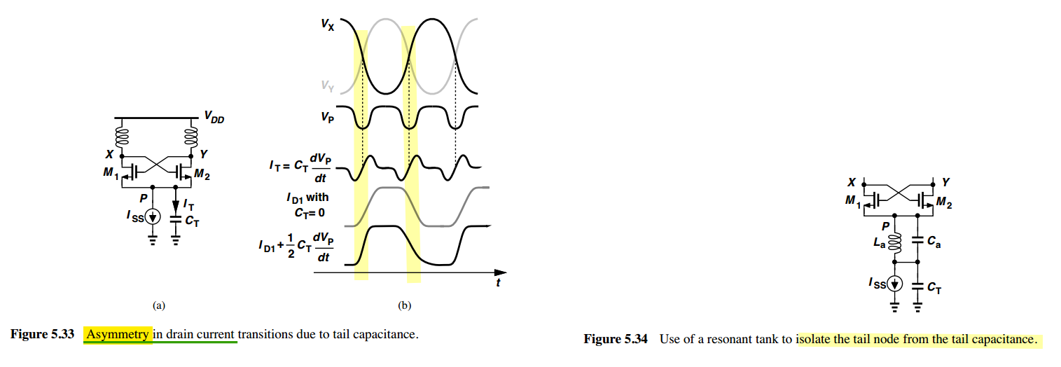
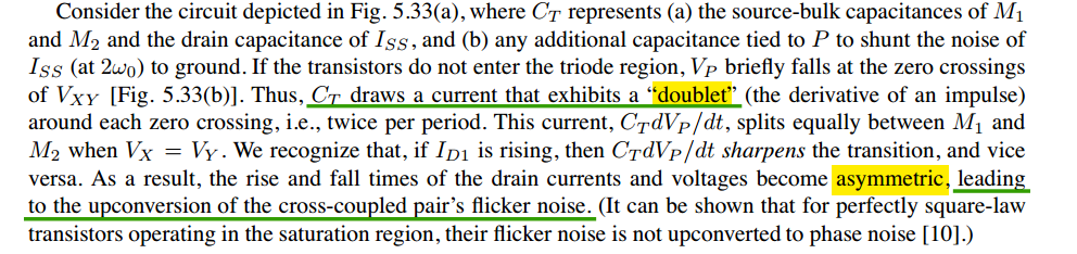
Flicker noise of the tail transistor \[ M_{\mathrm{tail}}\text{ flicker} \rightarrow \Delta I_T \rightarrow \Delta A,\Delta H_n \rightarrow \Delta\omega_0. \]
Tail capacitance affecting pair flicker \[ C_T \rightarrow \text{asymmetric }i_{D1}(t) \rightarrow \Gamma_{\mathrm{eff,DC}}\neq0 \rightarrow M_{1,2}\text{ flicker upconversion}. \]
The tail capacitor is not itself a flicker-noise generator. It modifies the periodic operating point and breaks the cancellation of the cross-coupled pair’s flicker-noise-induced phase perturbations
Chembiyan's Phase Perturbation
Chembiyan T, "Brownian Motion And The Oscillator Phase Noise" [link]
—, "Jitter and Phase Noise in Oscillators" [link]
—, "Jitter and Phase Noise in Phase Locked Loops" [link]
—, "PLLs and reference spurs" [link]
w/ stationary noise with Gaussian PDF
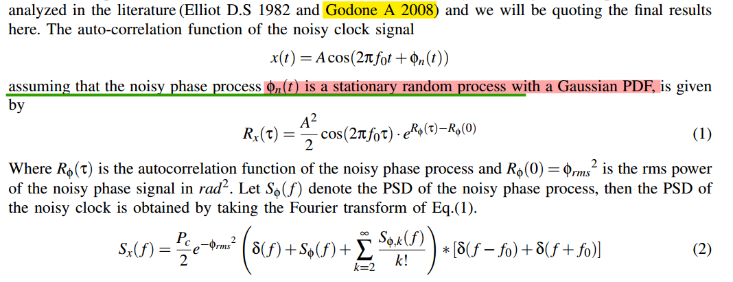
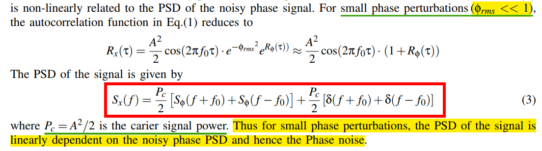
If keep \(\phi_{rms}\) in \(R_x(\tau)\), i.e. \[ R_x(\tau)=\frac{A^2}{2}e^{-\phi_{rms}^2}\cos(2\pi f_0 \tau)e^{R_\phi(\tau)}\approx \frac{A^2}{2}e^{-\phi_{rms}^2}\cos(2\pi f_0 \tau)(1+R_\phi(\tau)) \] The PSD of the signal is \[ S_x(f) = \mathcal{F} \{ R_x(\tau) \} = \frac{P_c}{2}e^{-\phi_{rms}^2}\left[S_\phi(f+f_0)+S_\phi(f-f_0)\right] + \frac{P_c}{2}e^{-\phi_{rms}^2}\left[\delta(f+f_0)+\delta(f-f_0)\right] \] ❗❗above Eq isn't consistent with stationary white noise process - the following section
w/ stationary white noise
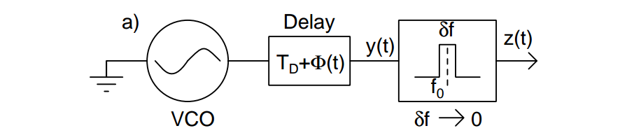
Assuming that the delay line is noiseless
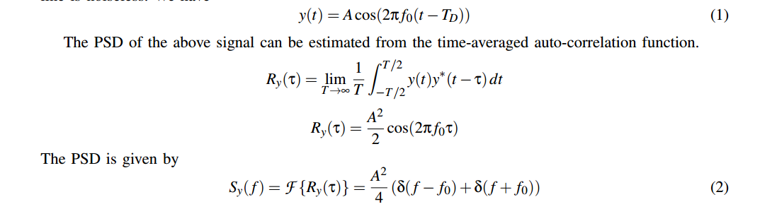
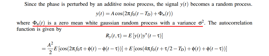
Expanding the cosine function we get \[\begin{align} R_y(t,\tau) &= \frac{A^2}{2}\left\{\cos(2\pi f_0\tau)E[\cos(\phi(t)-\phi(t-\tau))] - \sin(2\pi f_0\tau)E[\sin(\phi(t)-\phi(t-\tau))]\right\} \\ &+ \frac{A^2}{2}\left\{\cos(4\pi f_0(t+\tau/2-T_D))E[\cos(\phi(t)+\phi(t-\tau))] - \sin(4\pi f_0(t+\tau/2-T_D))E[\sin(\phi(t)+\phi(t-\tau))] \right\} \end{align}\]
where, both the process \(\phi(t)-\phi(t-\tau)\) and \(\phi(t)+\phi(t-\tau)\) are independent of time \(t\), i.e. \(E[\cos(\phi(t)+\phi(t-\tau))] = m_{\cos+}(\tau)\), \(E[\cos(\phi(t)-\phi(t-\tau))] = m_{\cos-}(\tau)\), \(E[\sin(\phi(t)+\phi(t-\tau))] = m_{\sin+}(\tau)\) and \(E[\sin(\phi(t)-\phi(t-\tau))] = m_{\sin-}(\tau)\)
we obtain \[\begin{align} R_y(t,\tau) &= \frac{A^2}{2}\left\{\cos(2\pi f_0\tau)m_{\cos-}(\tau) - \sin(2\pi f_0\tau)m_{\sin-}(\tau)\right\} \\ &+ \frac{A^2}{2}\left\{\cos(4\pi f_0(t+\tau/2-T_D))m_{\cos+}(\tau) - \sin(4\pi f_0(t+\tau/2-T_D))m_{\sin+}(\tau) \right\} \end{align}\]
The second term in the above expression is periodic in \(t\) and to estimate its PSD, we compute the
time-averaged autocorrelation function \[
R_y(\tau) = \frac{A^2}{2}\left\{\cos(2\pi f_0\tau)m_{\cos-}(\tau) -
\sin(2\pi f_0\tau)m_{\sin-}(\tau)\right\}
\] 
After nontrivial derivation

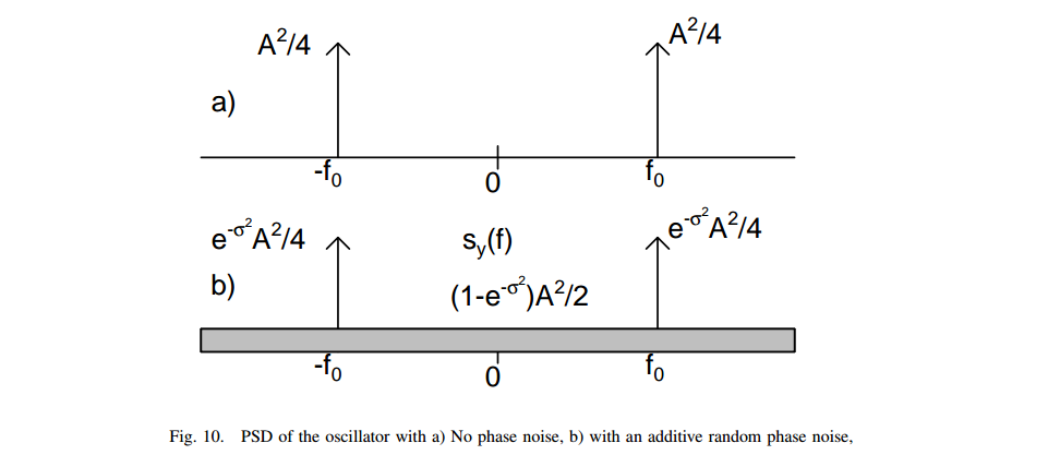
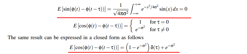
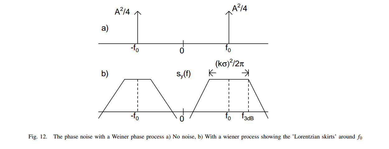
w/ Weiner process
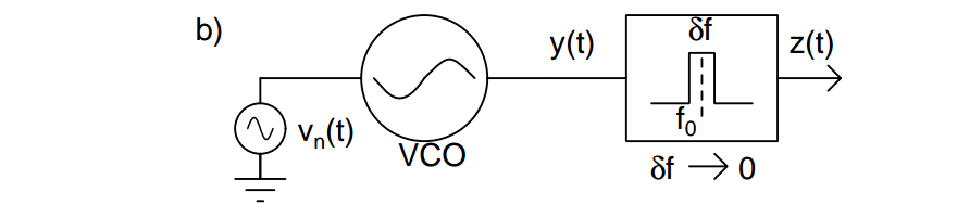
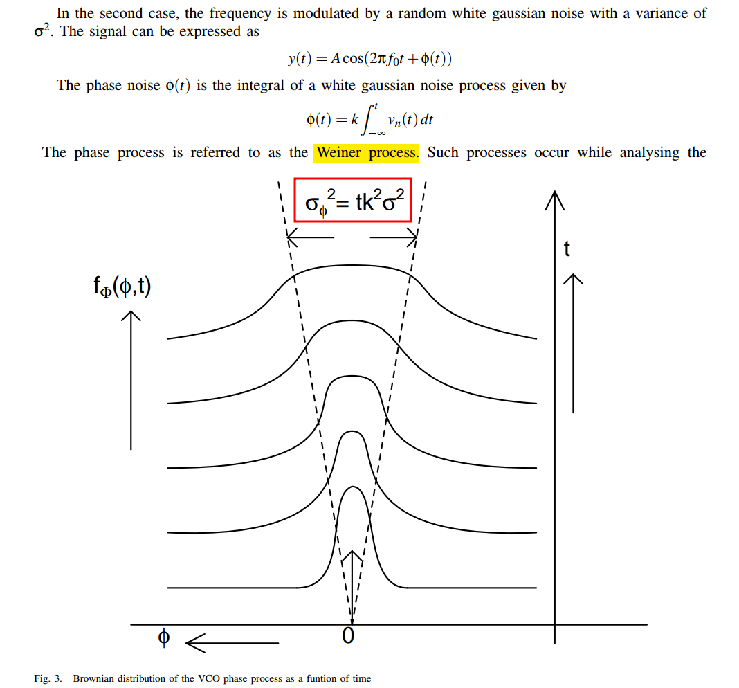
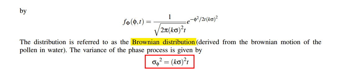
The phase process \(\phi(t)\) is also gaussian but with an increasing variance which grows linearly with time \(t\)
\[\begin{align} R_y(t,\tau) &= \frac{A^2}{2}\left\{\cos(2\pi f_0\tau)E[\cos(\phi(t)-\phi(t-\tau))] - \sin(2\pi f_0\tau)E[\sin(\phi(t)-\phi(t-\tau))]\right\} \\ &+ \frac{A^2}{2}\left\{\cos(4\pi f_0(t+\tau/2-T_D)E[\cos(\phi(t)+\phi(t-\tau))] - \sin(4\pi f_0(t+\tau/2-T_D)E[\sin(\phi(t)+\phi(t-\tau))] \right\} \end{align}\]
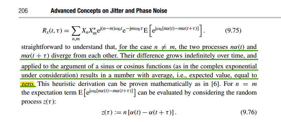
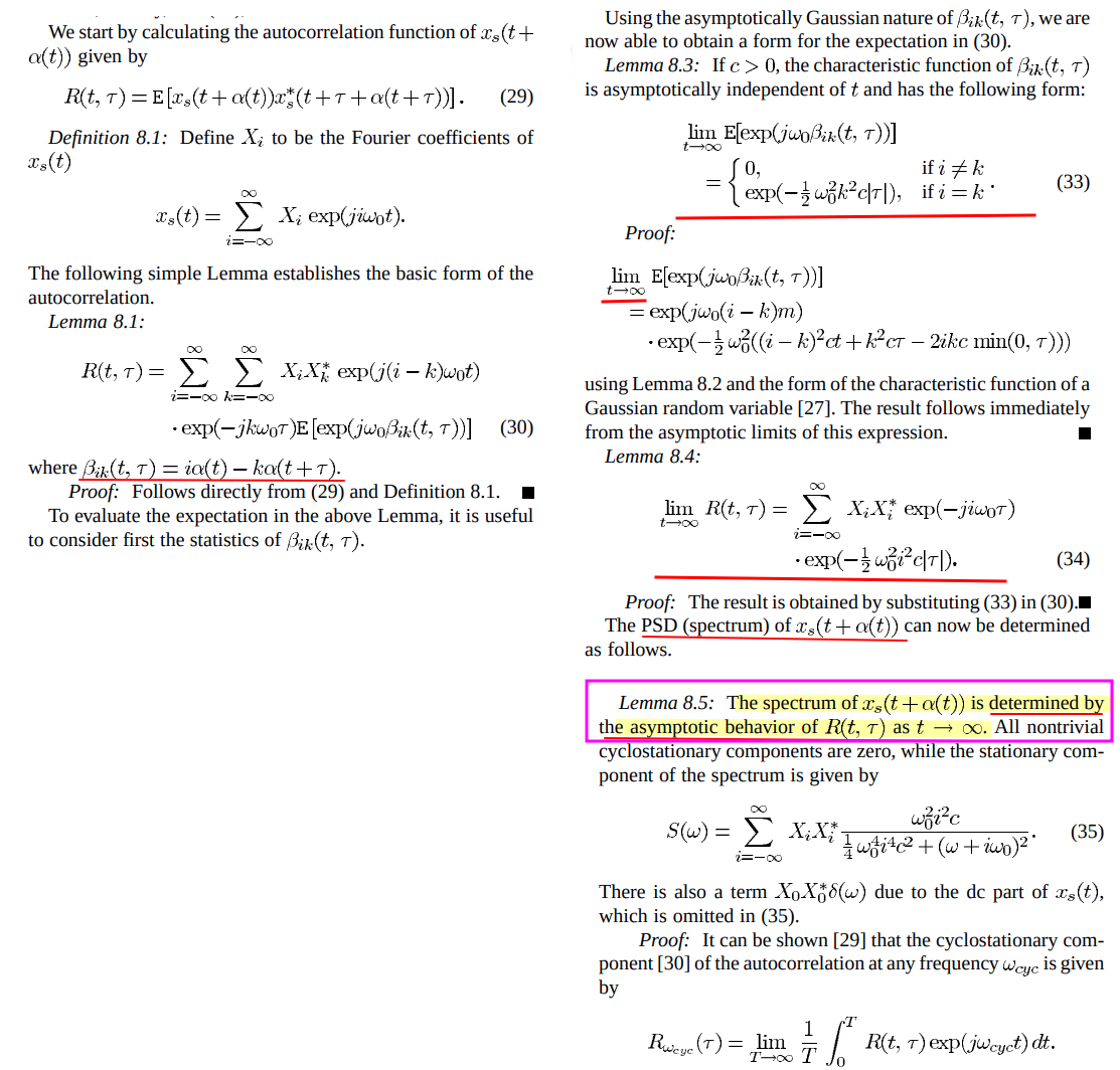
The spectrum of \(y(t)\) is determined by the asymptotic behavior of \(R_y(t,\tau)\) as \(t\to \infty\)
❗❗ \(\lim_{t\to\infty}R_y(t,\tau)\) rather than time-averaged autocorrelation function of cyclostationary process, ref. Demir's paper
We define \(\zeta(t, \tau)=\phi(t)+\phi(t-\tau) = \phi(t)-\phi(t-\tau) + 2\phi(t-\tau)\), the expected value of \(\zeta(t,\tau)\) is 0, the variance is \(\sigma_{\zeta}^2=(k\sigma)^2(\tau + 4(t-\tau))=(k\sigma)^2(4t-3\tau)\) \[ E[\cos(\zeta(t,\tau))]=\frac{1}{\sqrt{2\pi \sigma_{\zeta}^2}}\int_{-\infty}^{\infty}e^{-\zeta^2/2\sigma_{\zeta}^2}\cos(\zeta)d\zeta = e^{-\sigma_{\zeta}^2/2}=e^{-(k\sigma)^2(4t-\tau)} \] i.e., \(\lim _{t\to \infty} E[\cos(\zeta(t,\tau))] = \lim_{t\to \infty}e^{-(k\sigma)^2(4t-\tau)} = 0\)
For \(E[\sin(\zeta(t,\tau))]\), we have \[ E[\sin(\zeta(t,\tau))] = \frac{1}{\sqrt{2\pi \sigma_{\zeta}^2}}\int_{-\infty}^{\infty}e^{-\zeta^2/2\sigma_{\zeta}^2}\sin(\zeta)d\zeta \] i.e., \(E[\sin(\zeta(t,\tau))]\) is odd function, therefore \(E[\sin(\zeta(t,\tau))]=0\)
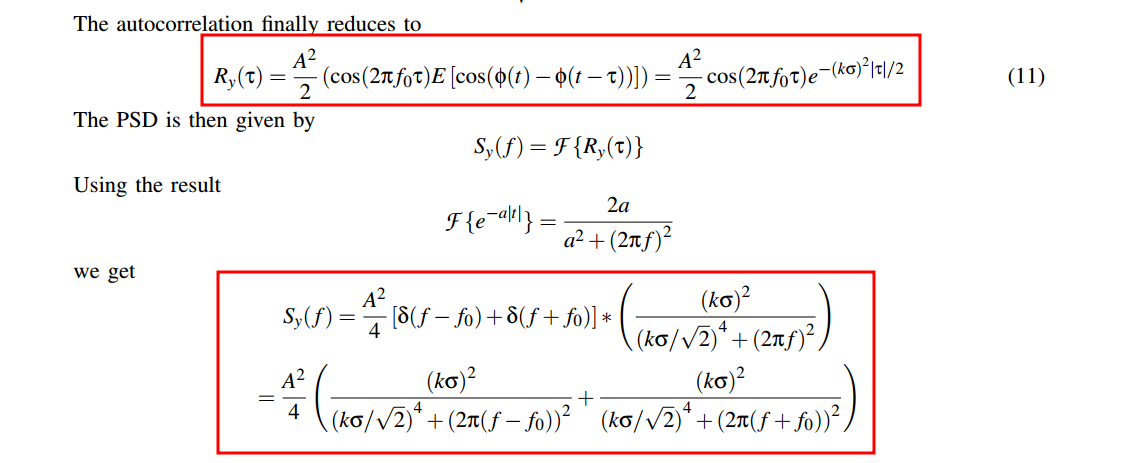
Finally, we obtain


ISF & PPV Extraction
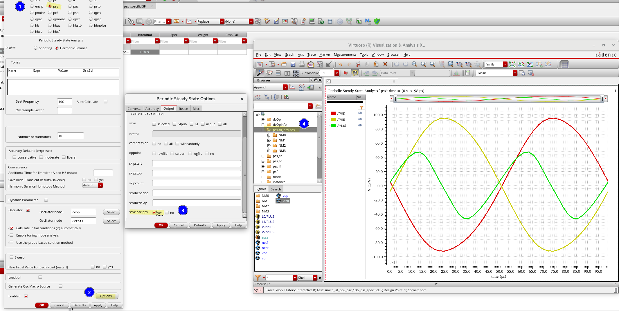
PPV values from pss/pnoise simulation in spectreRF [https://community.cadence.com/cadence_technology_forums/f/rf-design/35062/ppv-values-from-pss-pnoise-simulation-in-spectrerf]
ISF Function Extraction in Cadence Virtuoso [https://community.cadence.com/cadence_technology_forums/f/custom-ic-design/43969/isf-function-extraction-in-cadence-virtuoso]
ISF from Transient Analysis
David Dolt. ECEN 620 Network Theory - Broadband Circuit Design: "VCO ISF Simulation" [https://people.engr.tamu.edu/spalermo/ecen620/ISF_SIM.pdf]
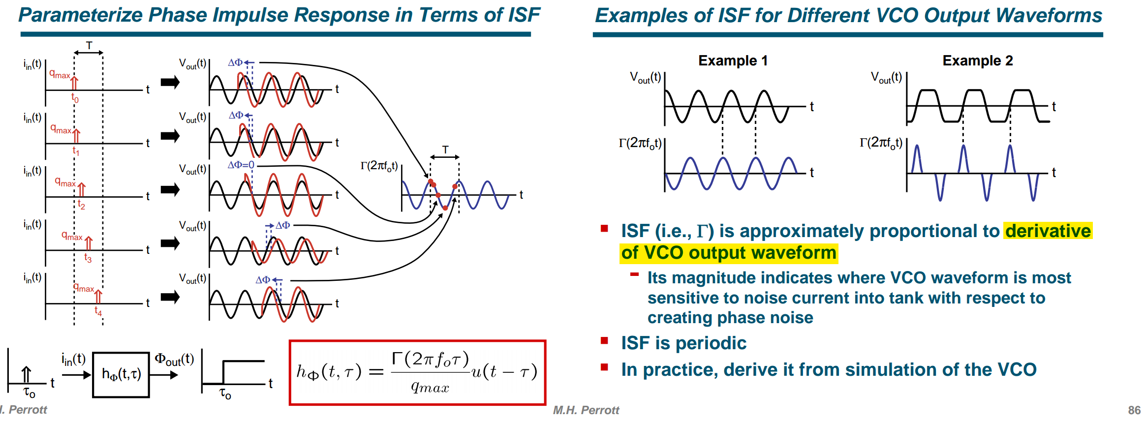
an injected current impulse with charge \(\Delta q=\int i(t)\,dt\), produces the permanent phase shift \[ \Delta\phi = \Gamma(\omega_0\tau)\frac{\Delta q}{q_{\max}}. \] Therefore, \[ \Gamma(\omega_0\tau) = \Delta\phi \frac{q_{\max}}{\Delta q}. \]
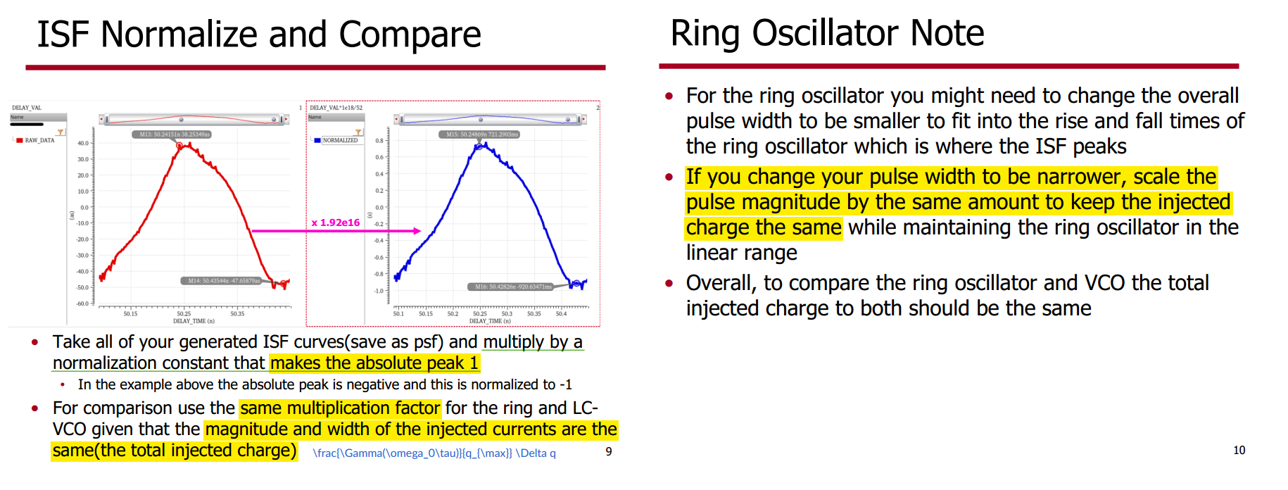 \[
\boxed{
\text{Same injected charge}
\quad\Longrightarrow\quad
\Delta\phi\propto\frac{\Gamma}{q_{\max}}
}
\] So:
\[
\boxed{
\text{Same injected charge}
\quad\Longrightarrow\quad
\Delta\phi\propto\frac{\Gamma}{q_{\max}}
}
\] So:
- To compare actual robustness against equal charge impulses, compare \(\Delta\phi/\Delta q\)
- To compare the formal dimensionless ISFs, multiply each simulated phase response by its own \(q_{\max}/\Delta q\)
Aditya Varma Muppala, ISF Simulation in Cadence Using Transient Analysis | Oscillators 07 | MMIC 12 [https://youtu.be/yiMn2rCtTXY]
\[ h_{\phi}(t,{\tau}) = \frac{\Gamma(\omega_0{\tau})}{q_{\max}} u(t-\tau) \]
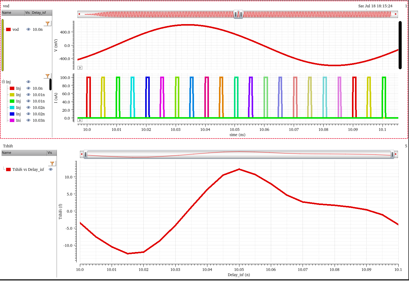
Therefore, \[ \boxed{ \Gamma(\omega_0{\tau}) = \frac{\Delta t}{T_0} \cdot 2\pi \cdot \frac{q_{\max}}{\Delta q} } \]
- \(\Delta q\) should be:
- not too small \(\rightarrow\) numerical error
- not too large \(\rightarrow\) nonlinearity
- \(\Delta t\) should be measured after the amplitude settles down (steady-state solution).
- The impulse should be injected after the oscillator stabilizes.
- The simulation step size used to measure \(\Delta t\) should be small.
- The transient-simulation error tolerance should be small.
Use cross function to find zero crossing when impulse is
off. Set significant digits to 16 and note down the value. \[
T_{i=0}
=
15.62239156\times10^{-9}
=
15.622\times10^{-9}
+
0.39156\times10^{-12}
\]
- Subtract it from the
crossoutput. ADE output truncates it, so break it up into different unit scales. - Check that the output is approximately zero before running sweeps.
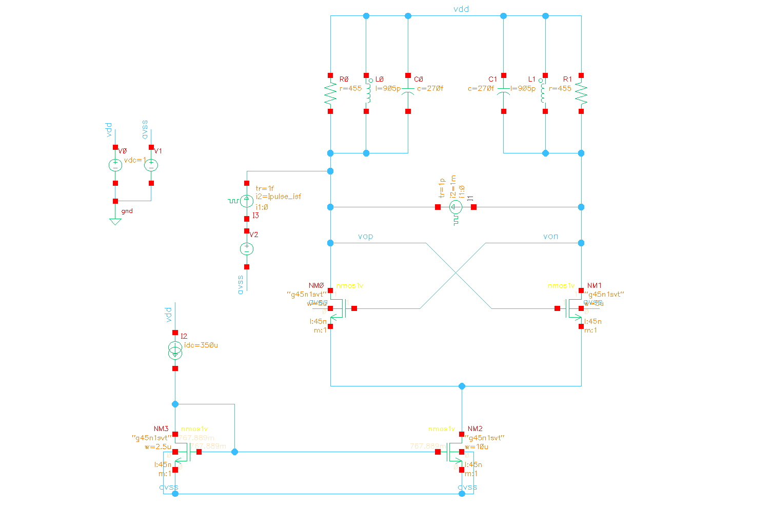
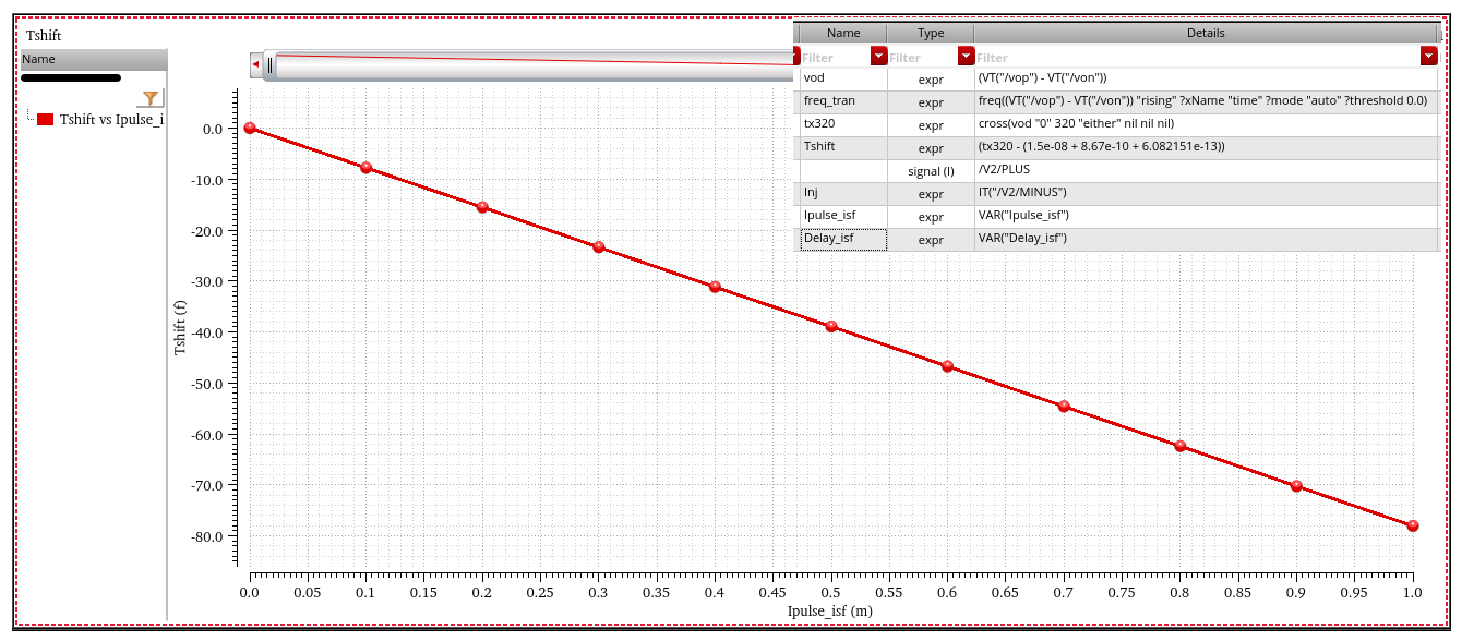
Oscillator Injection Linearity
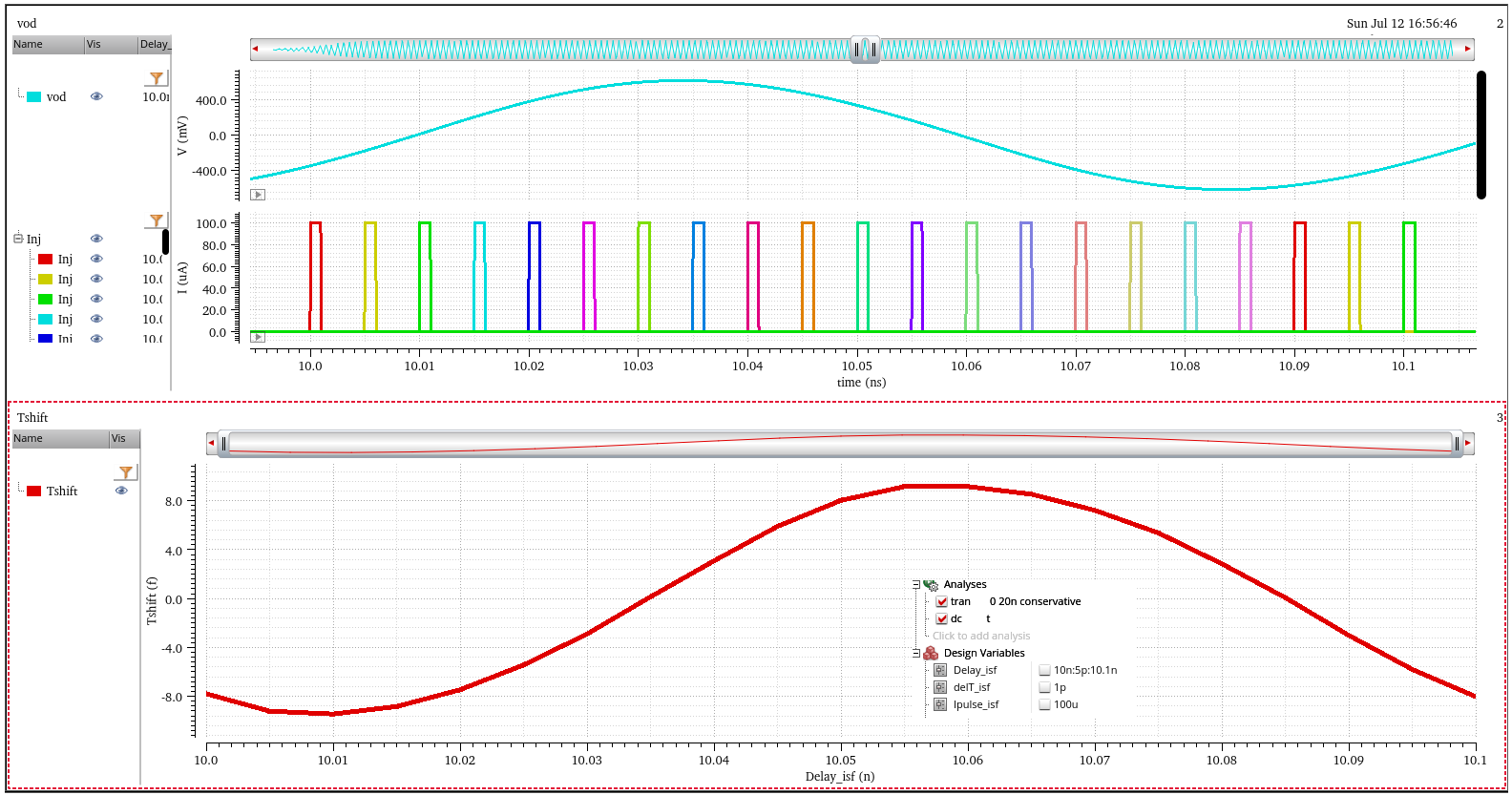
time shift by sweeping current pulse delay
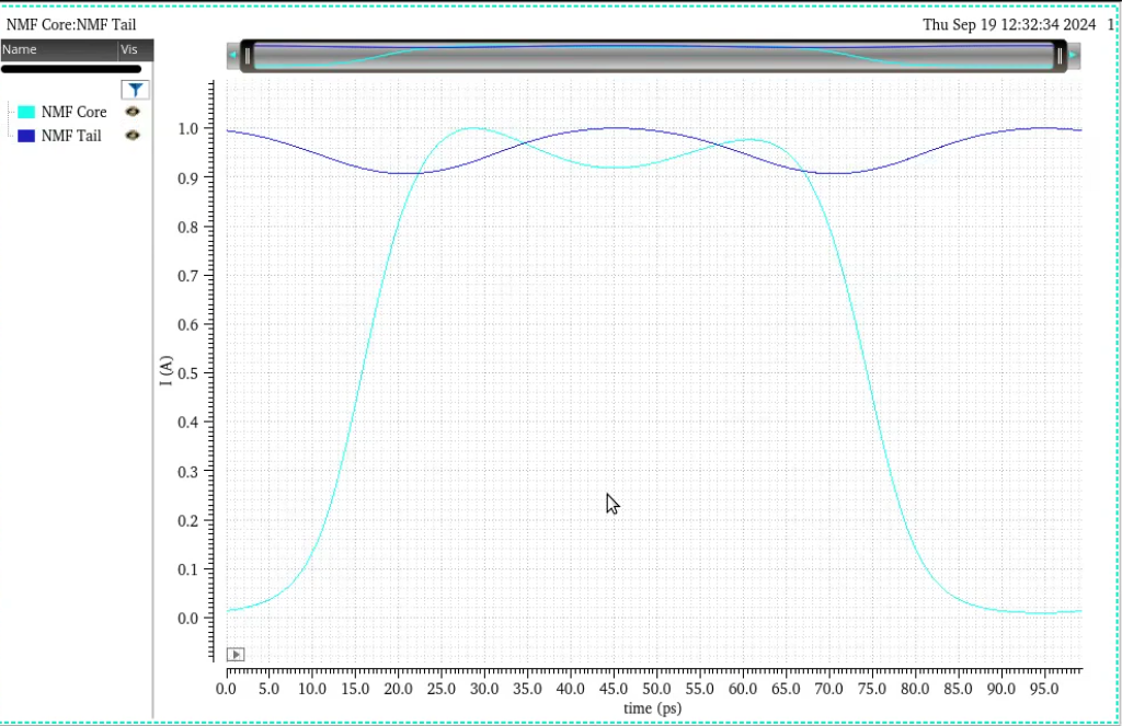
Aditya Varma Muppala, Noise Modulation Function (NMF) Simulation in Cadence | Oscillators 08 | MMIC 13 [https://youtu.be/CvcLG9cSreg] [code]
source-specific ISF
For example, if MOS drain thermal noise is represented as a current source between drain and source, then the perturbation used to obtain the source-specific ISF should also be injected between those same drain and source nodes
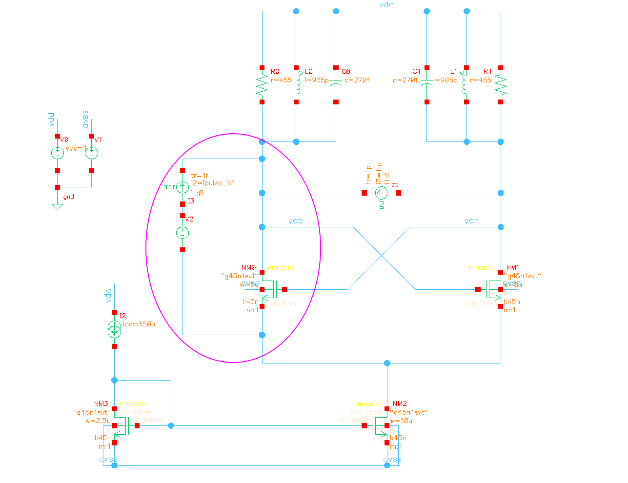
NMF \(\alpha_{NMF}(t)\) shall work with the corresponding source-specific ISF/PPV
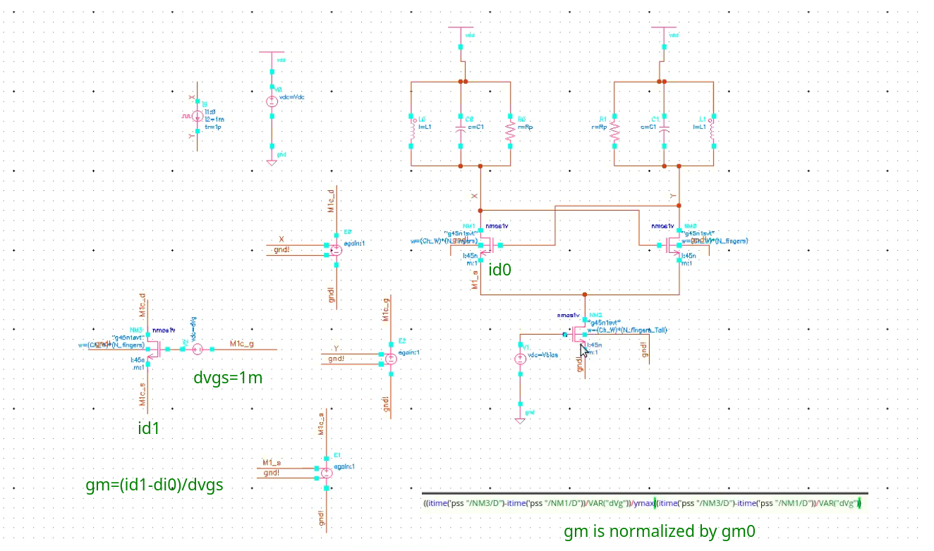 \[
\boxed{I_n(t)=4kT\gamma \cdot \textcolor{red}{g_m(t)} = 4kT\gamma \cdot
\textcolor{red}{\alpha_{NMF} (t)g_{m,0}}}
\]
\[
\boxed{I_n(t)=4kT\gamma \cdot \textcolor{red}{g_m(t)} = 4kT\gamma \cdot
\textcolor{red}{\alpha_{NMF} (t)g_{m,0}}}
\]
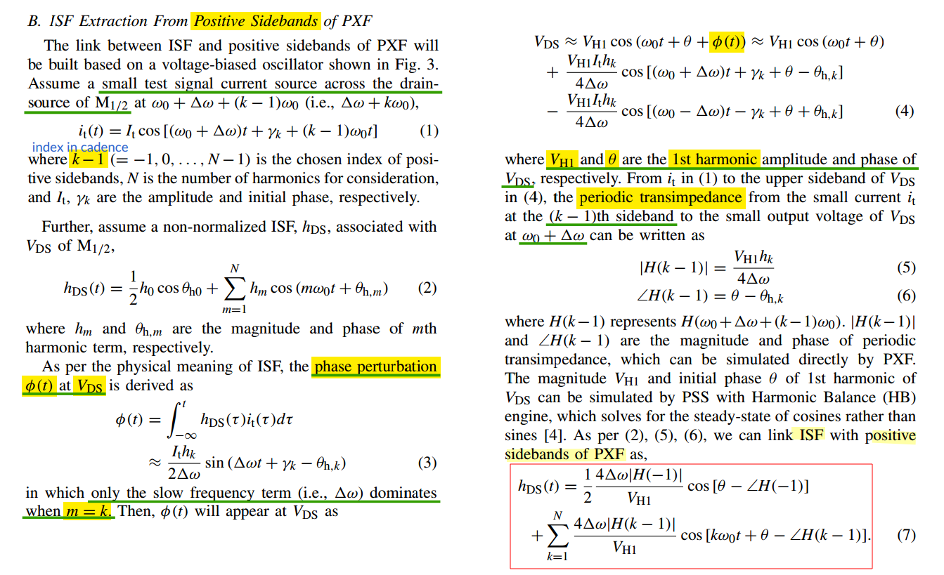
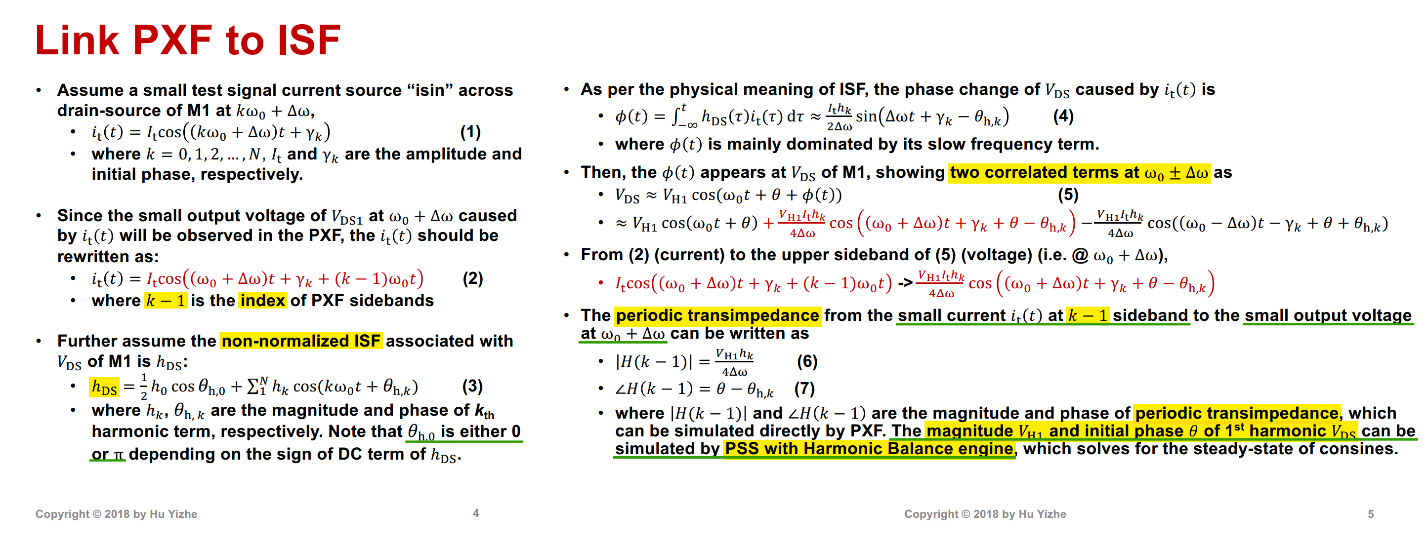
ISF from PSS + Positive Sidebands of PXF
Hu, Yizhe, "Intuitive Understanding of Flicker Noise Reduction via Narrowing of Conduction Angle in Voltage-Biased Oscillators," in IEEE Transactions on Circuits and Systems II: Express Briefs, vol. 66, no. 12, pp. 1962-1966, Dec. 2019 [https://sci-hub.ru/10.1109/TCSII.2019.2896483]
—. (2019). A Simulation Technique of Impulse Sensitivity Function (ISF) Based on Periodic Transfer Function (PXF). 10.13140/RG.2.2.32151.60323. [link]
—, "Oscillator Flicker Phase Noise: A Tutorial," in IEEE Transactions on Circuits and Systems II: Express Briefs, vol. 68, no. 2, pp. 538-544, Feb. 2021 [paper] [slides]
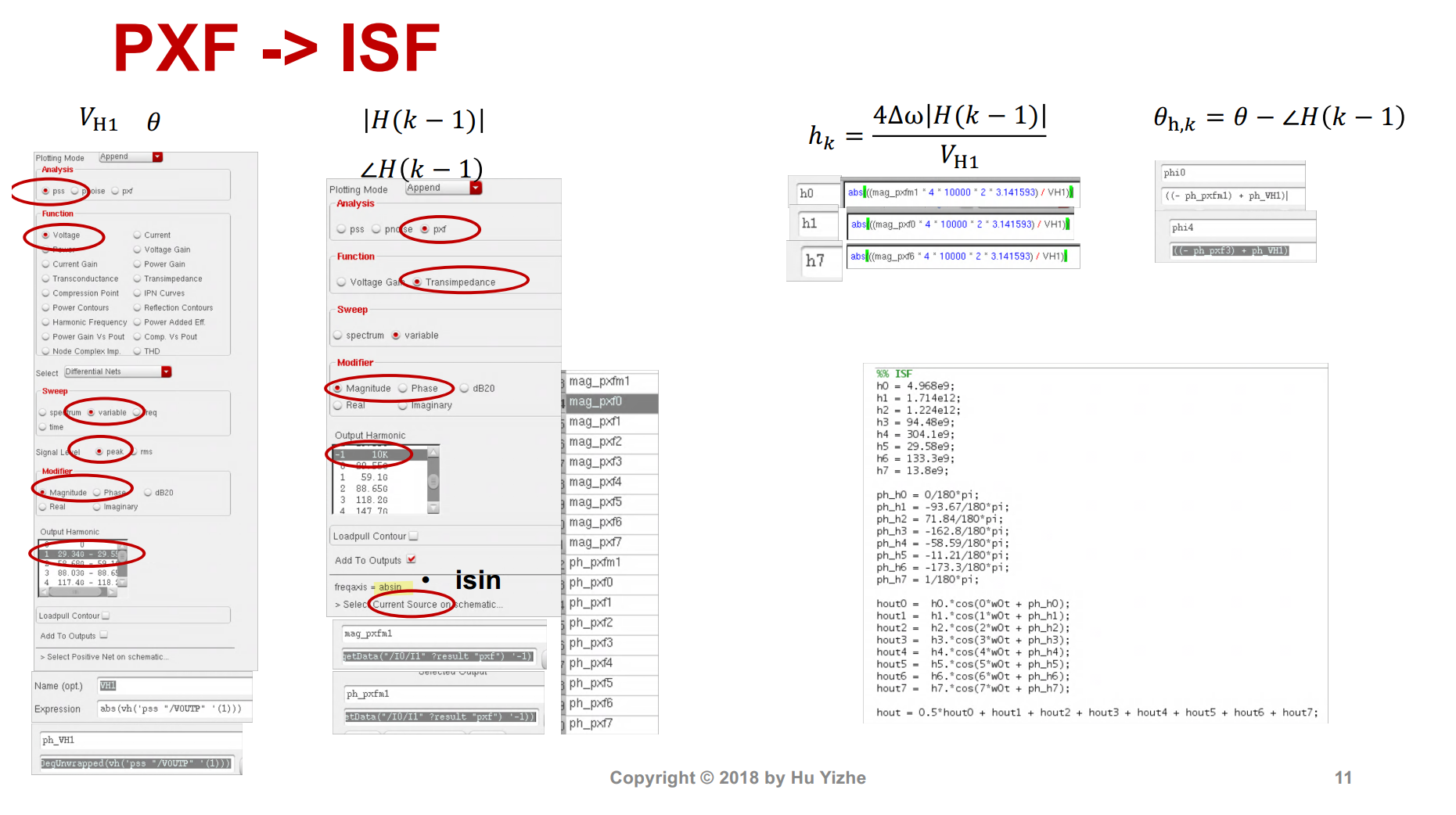
Aditya Varma Muppala, Fast Simulation of ISF and PPV using PSS and PXF in Cadence | Oscillators 12 | MMIC 19 [video note code]
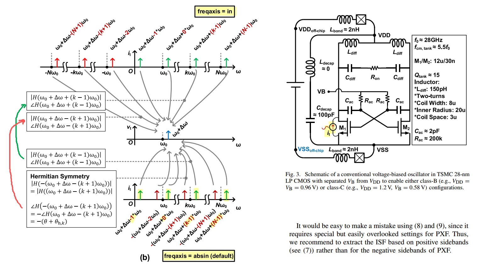
freqaxis=inPXF preserves the signed input-frequency axis. Therefore, both positive- and negative-frequency input sidebands can be used directly to extract the ISF
freqaxis=absin(default)Positive sidebands can be used directly. For negative sidebands, the PXF result corresponds to the Hermitian-symmetric positive-frequency response and must first be complex-conjugated; equivalently, retain its magnitude and reverse its phase
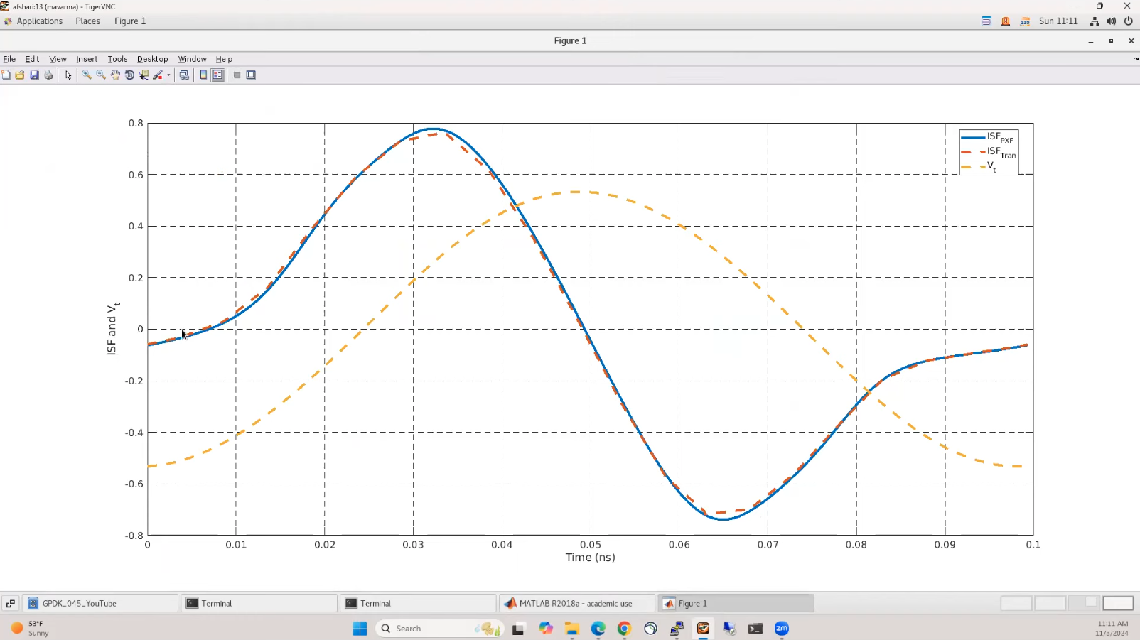
time reference between tran simulation and pss/pxf is different,
that's why circshift is used.
1 | ISF_Tran2 = interp1(time_Tran,-ISF_Tran{:,2},t); |
Complex Derivation of PXF from ISF
credits to chatgpt
Using a complex exponential representation gives the same result as the cosine derivation in the slides, provided the Fourier coefficient conventions are handled consistently.
1. Test Current
Instead of
\[ i_t(t)=I_t\cos\!\left((k\omega_0+\Delta\omega)t+\gamma_k\right), \]
use the analytic signal
\[ \tilde{i}_t(t) = I_t e^{j[(k\omega_0+\Delta\omega)t+\gamma_k]}. \]
2. Complex Fourier Series of ISF
The slide defines the real ISF as
\[ h_{DS}(t) = \frac12 h_0\cos\theta_0 + \sum_{m=1}^{\infty} h_m\cos(m\omega_0t+\theta_{h,m}). \]
Expressing it as a complex Fourier series,
\[ h_{DS}(t) = \sum_{m=-\infty}^{\infty} H_m e^{jm\omega_0t}, \]
gives
\[ H_{\pm m} = \frac{h_m}{2} e^{\pm j\theta_{h,m}}. \]
Hence
\[ H_{-k} = \frac{h_k}{2} e^{-j\theta_{h,k}}. \]
3. Phase Perturbation
The phase perturbation is
\[ \phi(t) = \int h_{DS}(t)i_t(t)\,dt. \]
Substituting the Fourier series,
\[ \phi(t) = I_t \sum_m \frac{H_m} {j[(m+k)\omega_0+\Delta\omega]} e^{j[(m+k)\omega_0+\Delta\omega]t}. \]
Only the slowly varying term contributes significantly, so choose
\[ m=-k, \]
which yields
\[ \boxed{ \phi(t) = \frac{I_tH_{-k}} {j\Delta\omega} e^{j(\Delta\omega t+\gamma_k)}. } \]
4. Oscillator Voltage
Represent the oscillator voltage as
\[ V_{DS} = V_{H1} e^{j(\omega_0t+\phi(t))}. \]
Using the small-angle approximation,
The small-angle approximation remains valid even if the phase perturbation is complex, provided its magnitude is small \(|\theta| \ll 1\)
\[ e^{j\phi}\approx1+j\phi, \]
gives
\[ V_{DS} \approx V_{H1}e^{j\omega_0t} + \frac{V_{H1}I_tH_{-k}} {\Delta\omega} e^{j(\omega_0+\Delta\omega)t}. \]
Therefore,
\[ \boxed{ H_{\mathrm{PXF}} = \frac{V_{H1}}{\Delta\omega} H_{-k}. } \]
5. Relation to the Slide
The fundamental drain voltage is
\[ v_{DS}(t) = V_{h1}\cos(\omega_0t+\theta), \]
whose complex coefficient is
\[ \boxed{ V_{H1} = \frac{V_{h1}}{2} e^{j\theta}. } \]
Since
\[ H_{-k} = \frac{h_k}{2} e^{-j\theta_{h,k}}, \]
we obtain
\[ H_{\mathrm{PXF}} = \frac{V_{h1}}{2\Delta\omega} \cdot \frac{h_k}{2} e^{j(\theta-\theta_{h,k})} = \frac{V_{h1}h_k} {4\Delta\omega} e^{j(\theta-\theta_{h,k})}. \]
Thus
\[ \boxed{ |H_{\mathrm{PXF}}| = \frac{V_{h1}h_k} {4\Delta\omega} } \]
and
\[ \boxed{ \angle H_{\mathrm{PXF}} = \theta-\theta_{h,k}. } \]
These are exactly Eqs. (6) and (7) in the slide.
Conclusion
The complex-exponential derivation is algebraically simpler than the cosine derivation. The only subtlety is the Fourier-series convention:
Positive-frequency coefficient of a cosine: \[ H_k=\frac{h_k}{2}e^{j\theta_{h,k}}. \]
Fundamental voltage phasor: \[ V_{H1}=\frac{V_{h1}}{2}e^{j\theta}. \]
Accounting for these \(1/2\) factors yields the identical PXF expression derived in the slides.
PPV from PSS inbuilt solver
Aditya Varma Muppala, Fast Simulation of ISF and PPV using PSS and PXF in Cadence | Oscillators 12 | MMIC 19 [https://youtu.be/Lu6VEWEEdxo]
TODO 📅
References
Jun Yin. ISSCC 2025 T10: mm-Wave Oscillator Design
Pietro Andreani. ISSCC 2011 T1: Integrated LC oscillators
—. ISSCC 2017 F2: Integrated Harmonic Oscillators
—. SSCS Distinguished Lecture: RF Harmonic Oscillators Integrated in Silicon Technologies [https://www.ieeetoronto.ca/wp-content/uploads/2020/06/DL-Toronto.pdf]
—. ESSCIRC 2019 Tutorials: RF Harmonic Oscillators Integrated in Silicon Technologies [https://youtu.be/k1I9nP9eEHE]
—. "Harmonic Oscillators in CMOS—A Tutorial Overview," in IEEE Open Journal of the Solid-State Circuits Society, vol. 1, pp. 2-17, 2021 [pdf]
C. Samori, ISSCC2016 T1 "Tutorial: Understanding Phase Noise in LC VCOs"
—, "Understanding Phase Noise in LC VCOs: A Key Problem in RF Integrated Circuits," in IEEE Solid-State Circuits Magazine, vol. 8, no. 4, pp. 81-91, Fall 2016 [https://sci-hub.ru/10.1109/MSSC.2016.2573979]
—, Phase Noise in LC Oscillators: From Basic Concepts to Advanced Topologies [https://www.ieeetoronto.ca/wp-content/uploads/2020/06/DL-VCO-short.pdf]
A. Hajimiri, RFIC2024 "Noise in Oscillators from Understanding to Design"
Antonio Liscidini, ESSCIRC 2019 Tutorials: Phase Noise in Wireless Applications [https://youtu.be/nGmQ0JdoSE4]
Aditya Varma Muppala. Oscillators [https://youtube.com/playlist?list=PL9Trid0A4Da2fOmYTEjhAnUkGPxyiH7H6&si]
P.E. Allen - 2003. ECE 6440 - Frequency Synthesizers: Lecture 160 – Phase Noise - II [https://pallen.ece.gatech.edu/Academic/ECE_6440/Summer_2003/L160-PhNoII(2UP).pdf]
Jaeha Kim. Lecture 8. Special Topics: Design Trade -Offs in LC -Tuned Oscillators
Lacaita, Andrea Leonardo, Salvatore Levantino, and Carlo Samori. Integrated frequency synthesizers for wireless systems. Cambridge University Press, 2007.
Darabi H. Radio Frequency Integrated Circuits and Systems. 2nd ed. Cambridge University Press; 2020.
Hegazi, Emad, Asad Abidi, and Jacob Rael. The Designer's Guide to High-purity Oscillators. [New York]: Kluwer Academic Publishers, 2005. The Designer's Guide to High-Purity Oscillators
Bae, Woorham, and Deog-Kyoon Jeong. Analysis and Design of CMOS Clocking Circuits for Low Phase Noise. Institution of Engineering and Technology, 2020.
M. Babaie, M. Shahmohammadi, R. B. Staszewski, (2019) "RF CMOS Oscillators for Modern Wireless Applications" River Publishers [https://www.riverpublishers.com/pdf/ebook/RP_E9788793609488.pdf]
Rhee, Woogeun, and Zhiping Yu. Phase-Locked Loops: System Perspectives and Circuit Design Aspects. John Wiley & Sons, 2024.