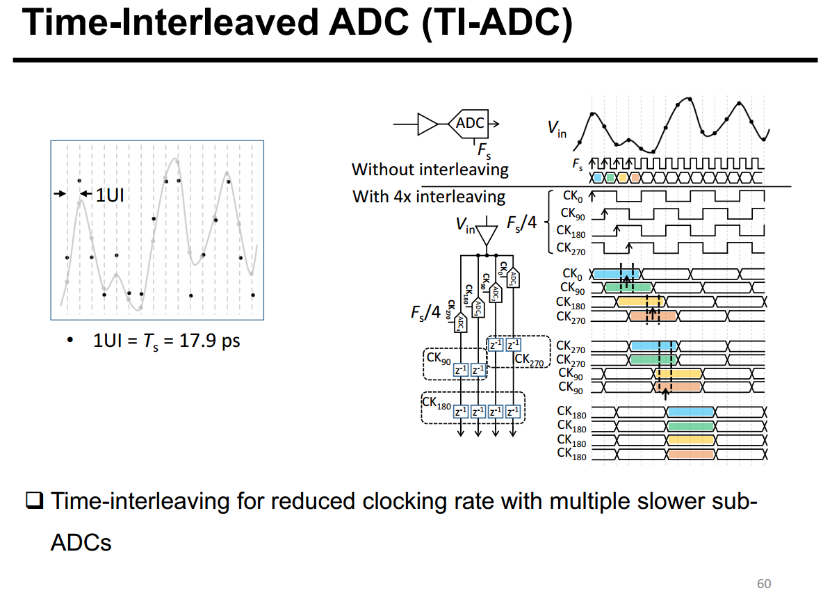
Time-Interleaved ADC (TI-ADC)
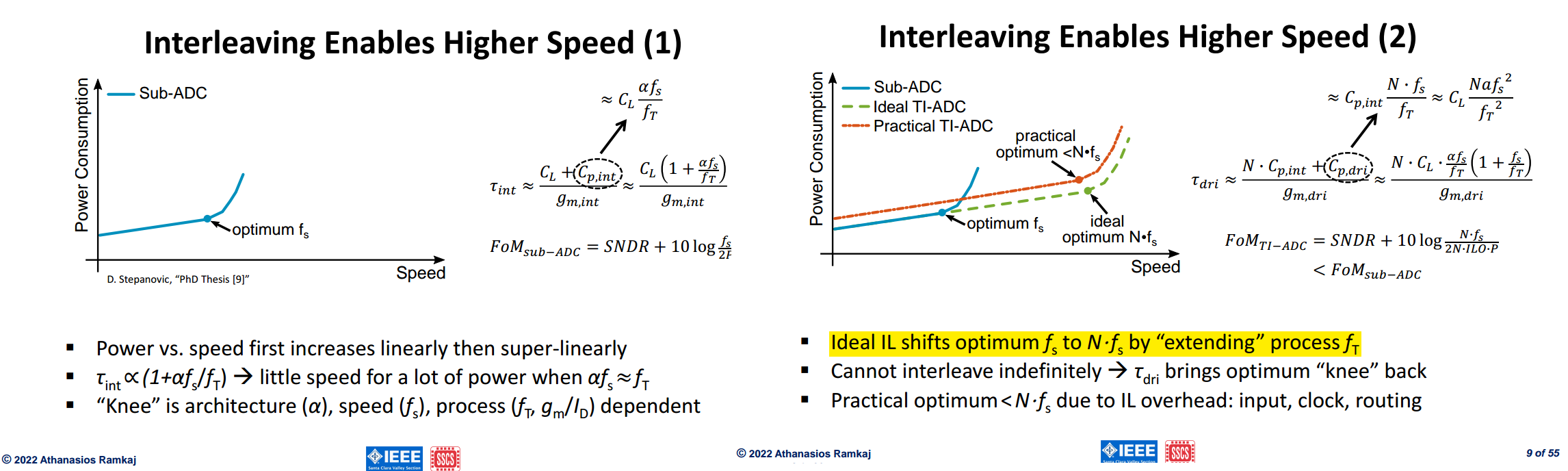
Frequency Domain Model

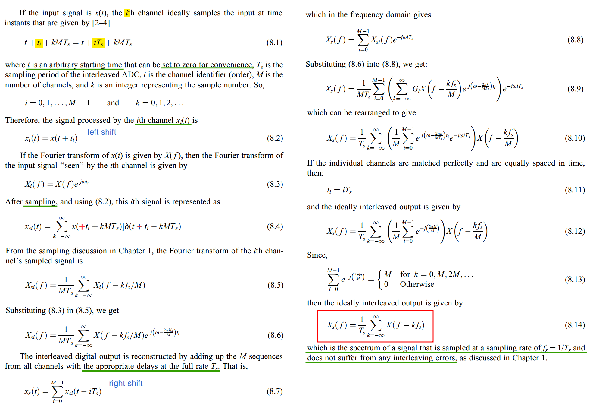
Why (8.14) means "sampled at \(T_s\)" \[ X_s(f) = \frac{1}{T_s}\sum_{k=-\infty}^{\infty} X(f - kf_s) \]
This spectrum is periodic with period \(f_s\): copies of \(X(f)\) sit at every multiple of \(f_s\), with weight \(1/T_s\). That is exactly the spectrum of uniform sampling at \(T_s\)
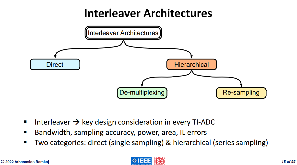
Interleaver Architectures
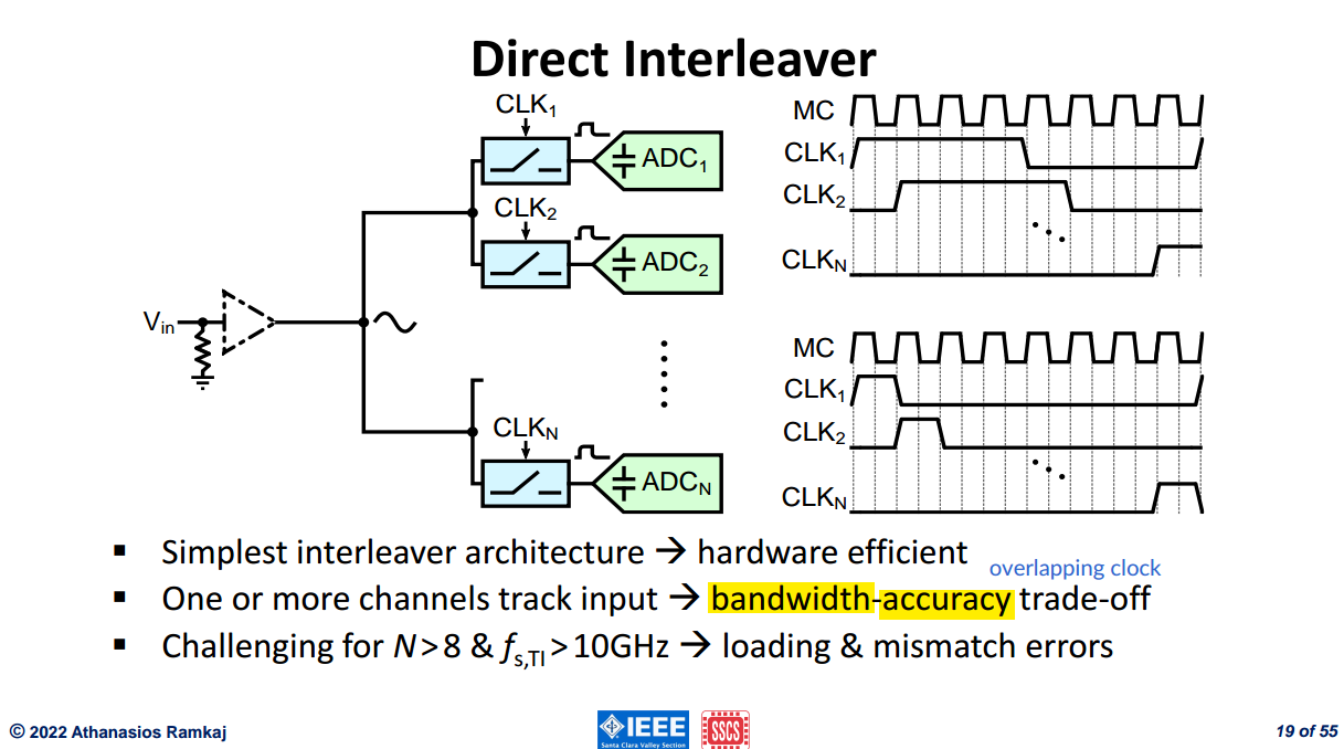
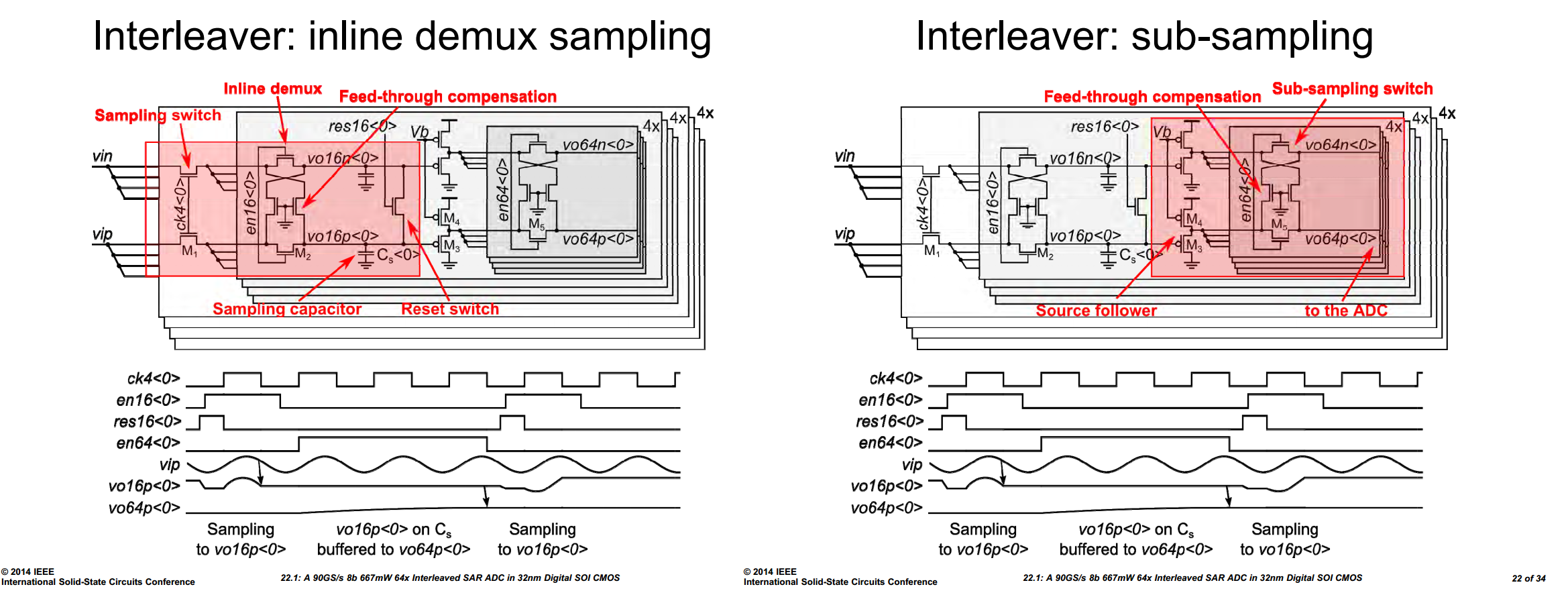
Direct Interleaver
similar to increase the resolution of the flash ADC with more parallel comparators
De-multiplexing Interleaver
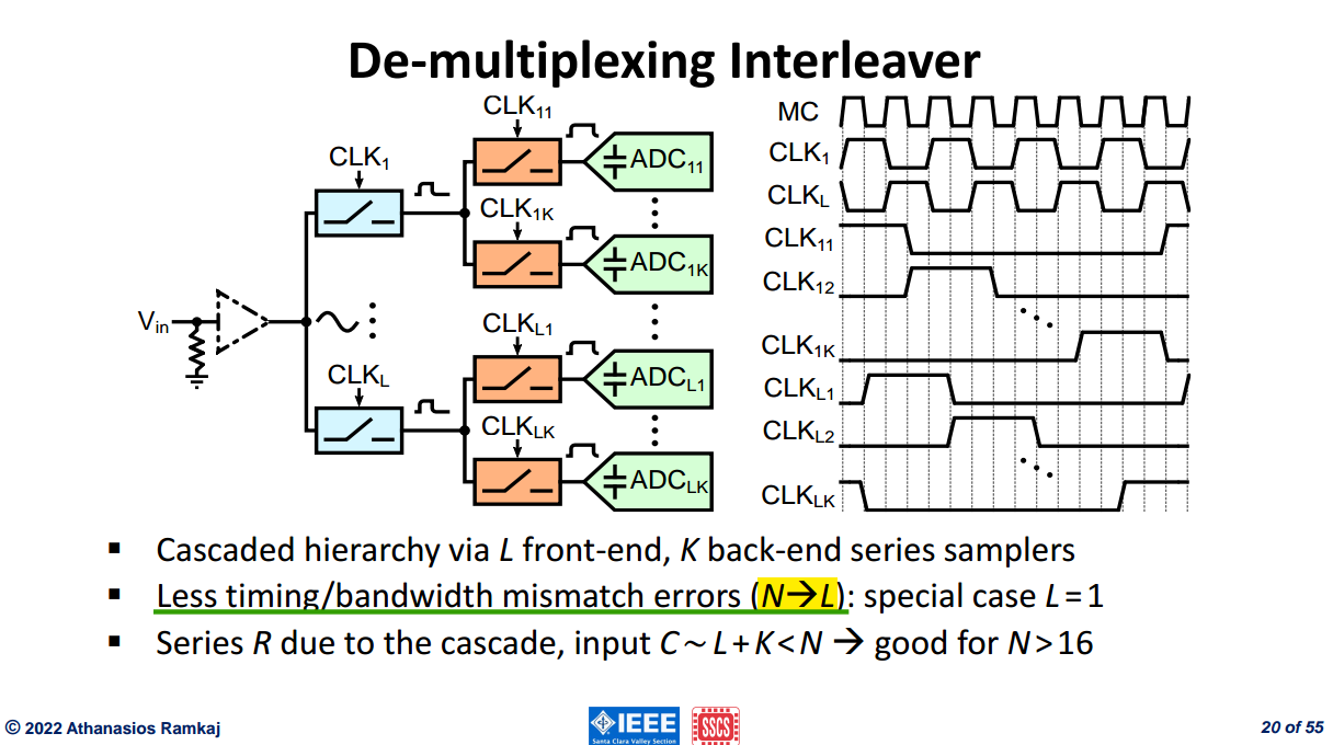
it is the front-end samplers that determine timing/bandwidth mismatch errors
only one front-end channel \(L=1\) eliminate any timing/bandwidth mismatch errors to the first order
Re-sampling Interleaver
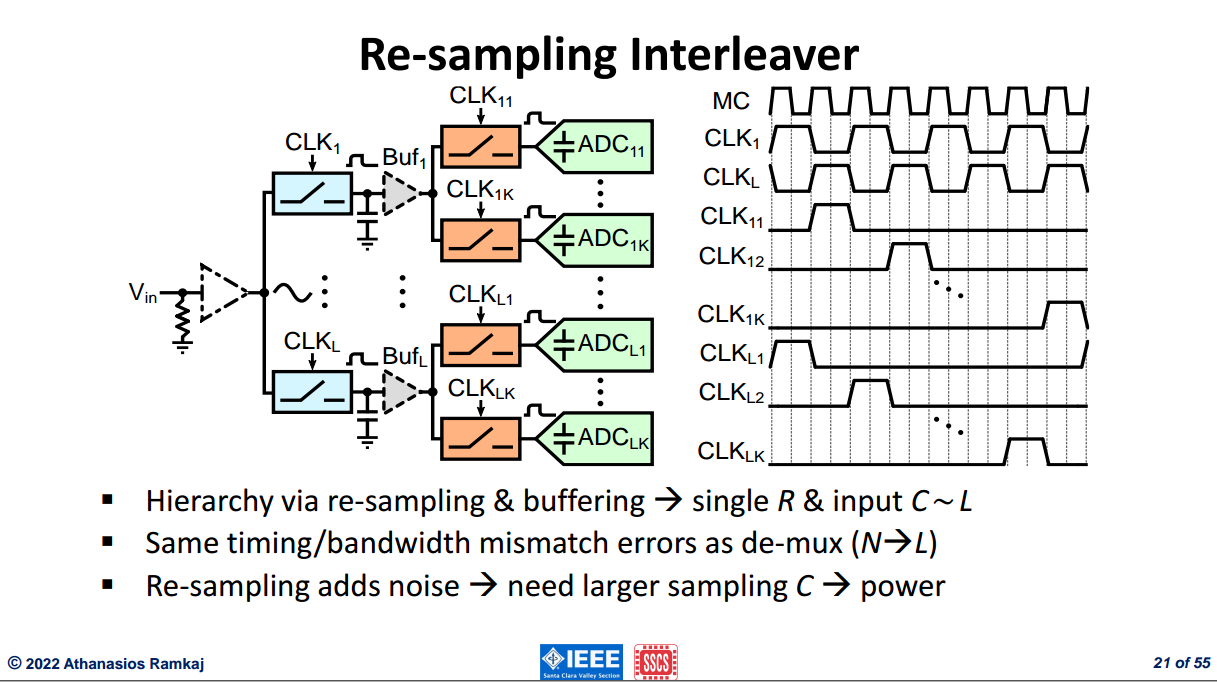
back-end re-sampling occur after the front-end, two \(\frac{KT}{C}\) contribution in total noise (De-multiplexing Interleaver only one \(\frac{KT}{C}\))
without buffer, charging distribution reduce signal and reduce SNR, but buffers give excess noise
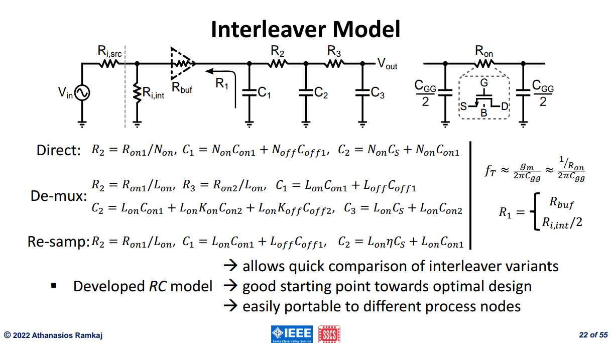
Interleaver Model
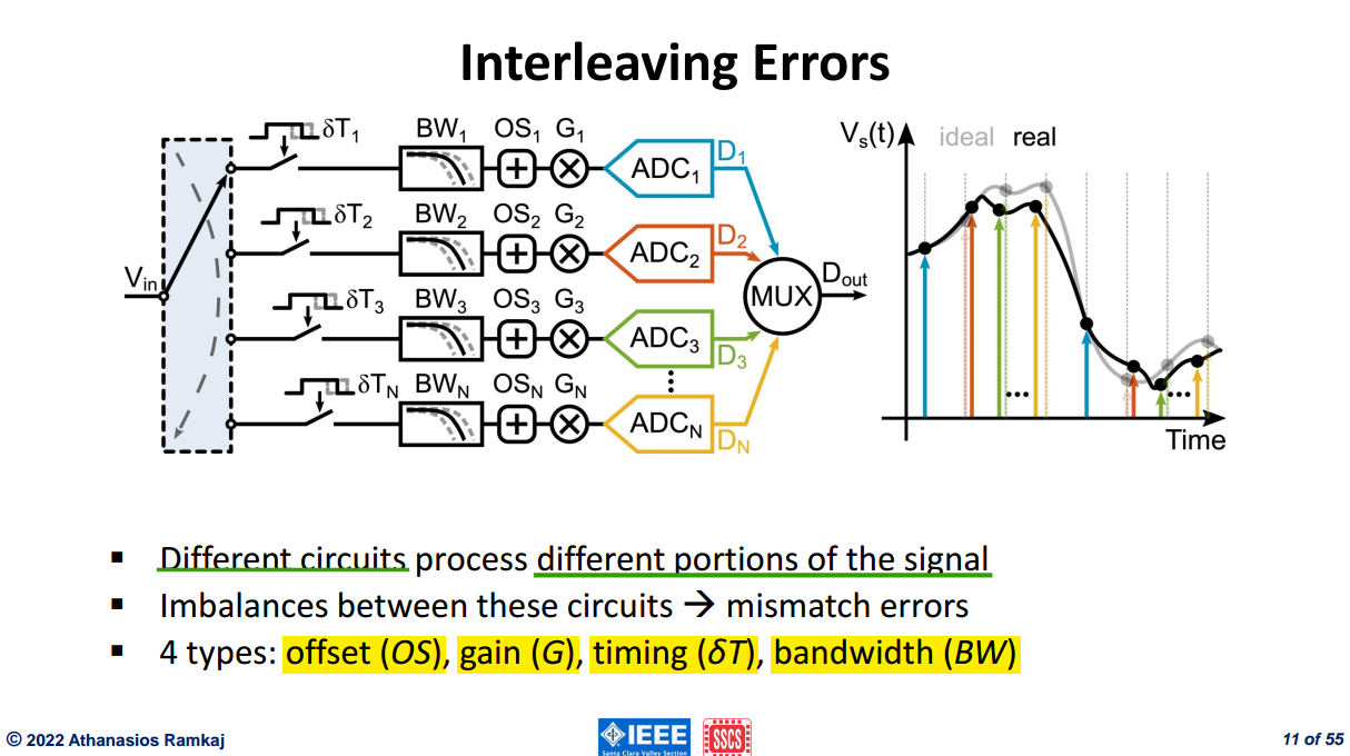
Interleaving Errors
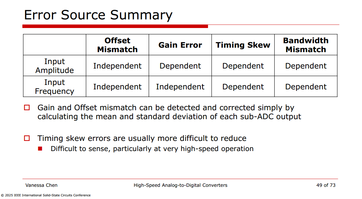
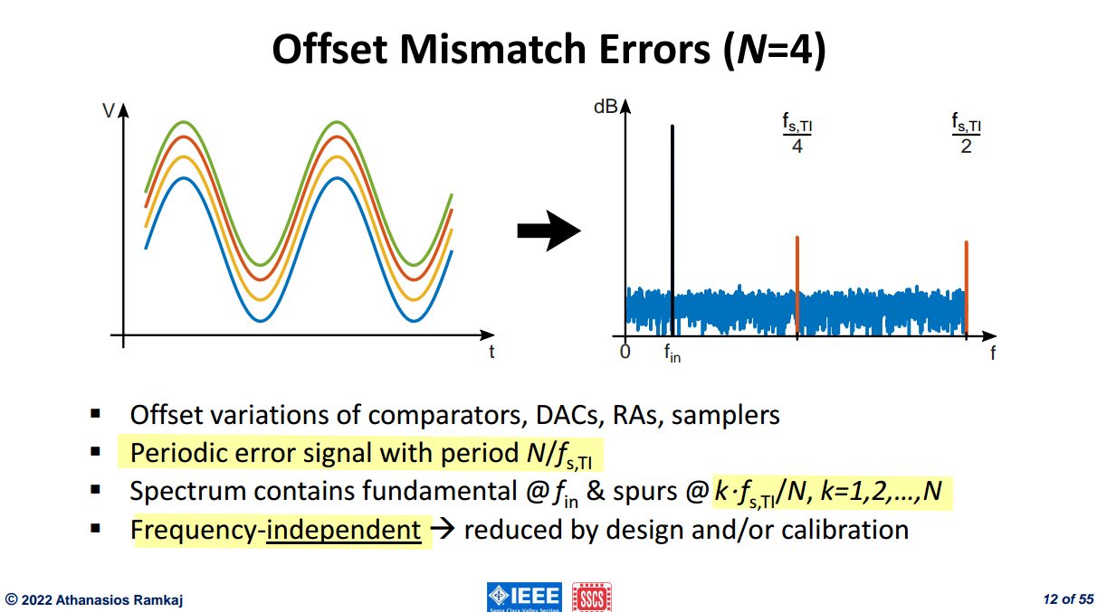
Offset Mismatch Errors
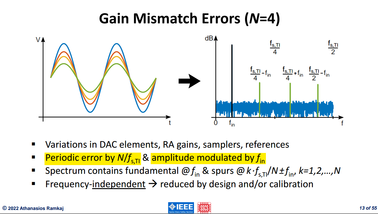
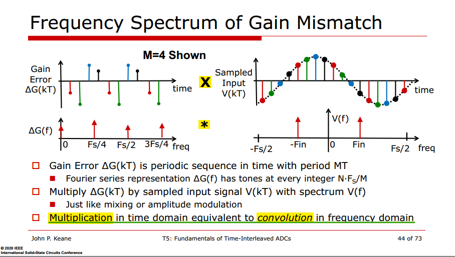
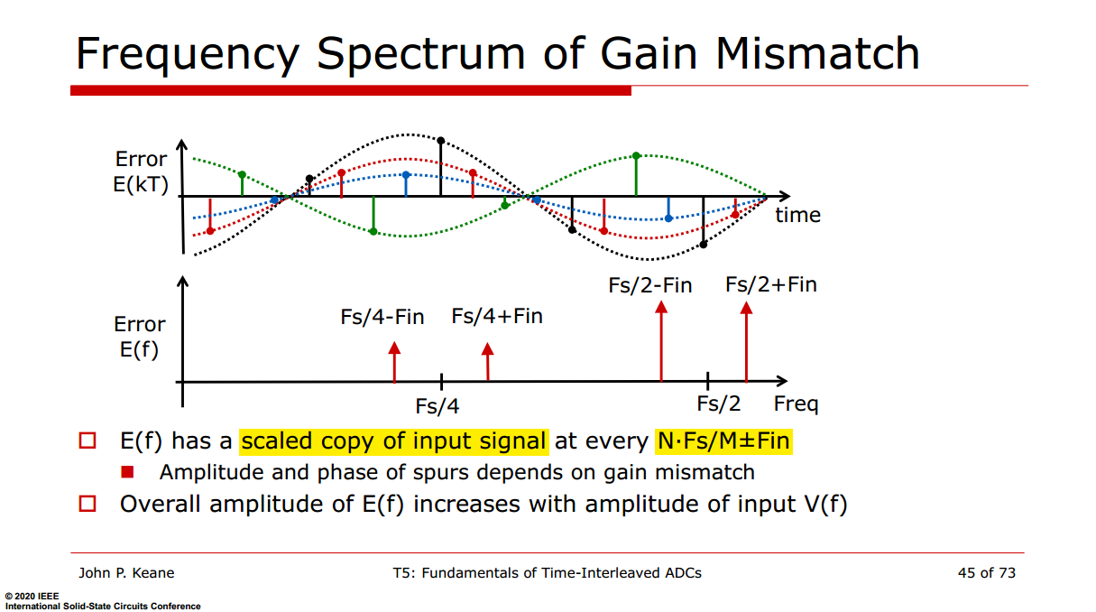
Gain Mismatch Errors
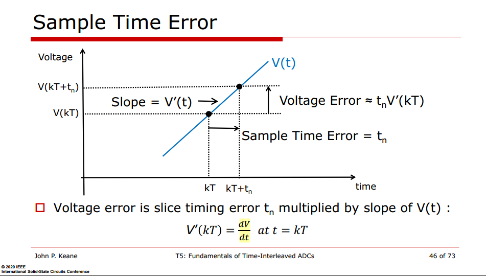
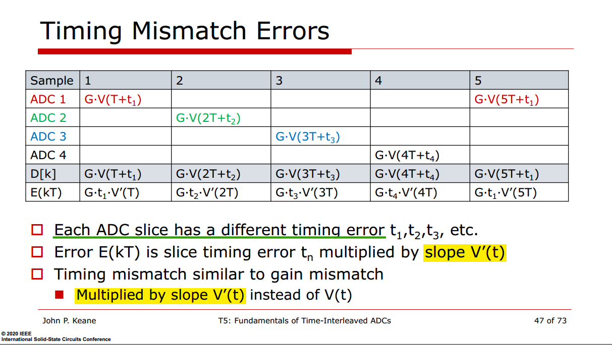
Timing Mismatch Errors
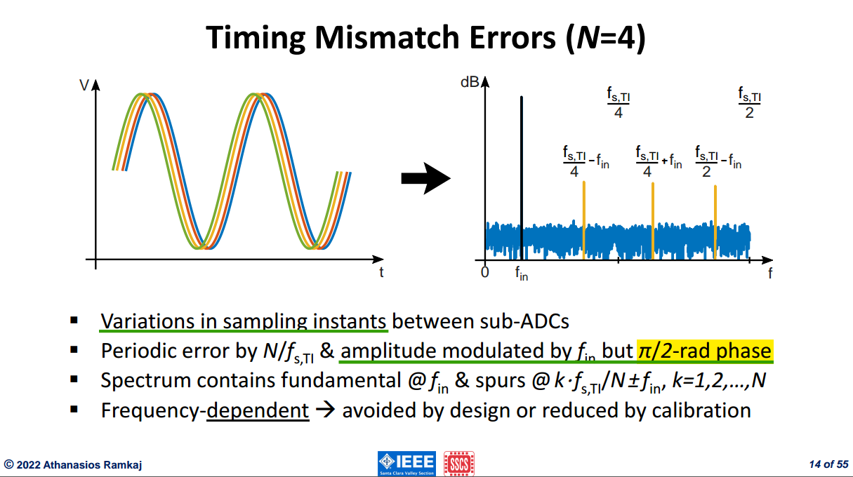
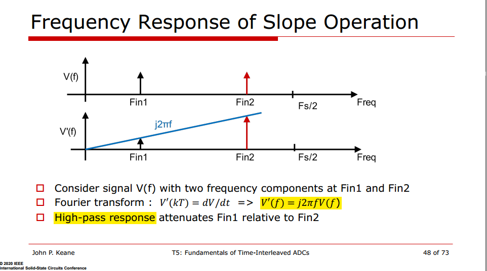
In the frequency domain,
\[ \mathcal{L}\left\{ \frac{dV(t)}{dt} \right\} \;\longrightarrow\; sV(s) \quad\text{and, for }s=j\omega,\quad j\omega V(j\omega). \]
The factor
\[ j=e^{j\pi/2} \]
introduces a \(+\pi/2\) (90°) phase shift, while \(\omega\) scales the magnitude proportionally to frequency.
In the time domain,
\[ \frac{d}{dt}\sin(\omega t) =\omega\cos(\omega t) =\omega\sin\left(\omega t+\frac{\pi}{2}\right). \]
Thus, differentiation produces two effects: magnitude scaling by \(\omega\) and a \(90^\circ\) phase advance.
Frequency-dependent: the higher frequency input signal \(f_\text{in}\), the larger error becomes
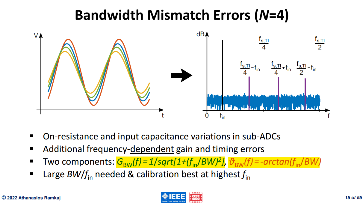
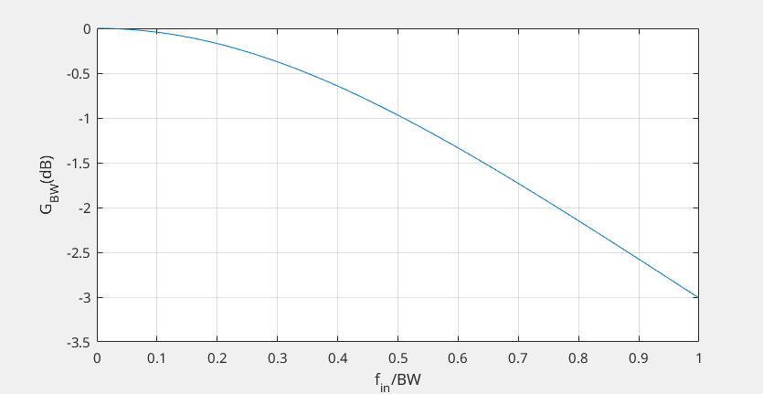
Bandwidth Mismatch Errors
ADC Clocking
Track-and-Hold (TAH), Sample-and-Holds (SAH)
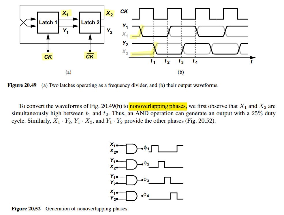
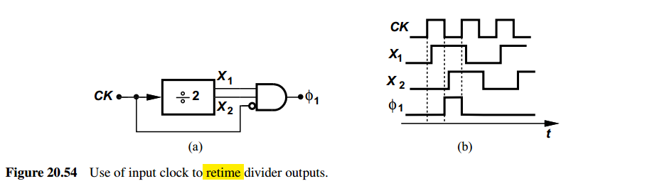
Note that the falling edge of \(\phi_1\) is determined by the rising edge of CK and is thus free from jitter and mismatch in \(X_1\), which accumulates jitter and phase mismatch
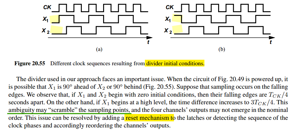
reset mechanism to the latches for nominal order
a clock generator for an eight-channel ADC
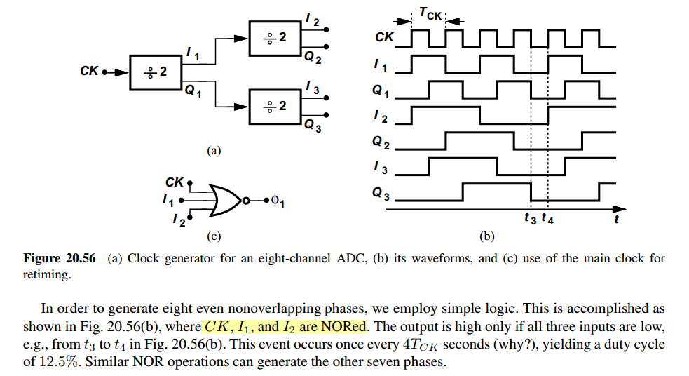
| NORed | \(\div 2\) | \(\div 2 \div 2\) | |
|---|---|---|---|
| \(\phi_1\) | \(\text{CK}\) | \(I_1\) | \(I_2\) |
| \(\phi_2\) | \(\overline{\text{CK}}\) | \(Q_1\) | \(I_3\) |
| \(\phi_3\) | \(\text{CK}\) | \(\overline{I_1}\) | \(Q_2\) |
| \(\phi_4\) | \(\overline{\text{CK}}\) | \(\overline{Q_1}\) | \(Q_3\) |
| \(\phi_5\) | \(\text{CK}\) | \(I_1\) | \(\overline{I_2}\) |
| \(\phi_6\) | \(\overline{\text{CK}}\) | \(Q_1\) | \(\overline{I_3}\) |
| \(\phi_7\) | \(\text{CK}\) | \(\overline{I_1}\) | \(\overline{Q_2}\) |
| \(\phi_8\) | \(\overline{\text{CK}}\) | \(\overline{Q_1}\) | \(\overline{Q_3}\) |
\(\text{CK}\), \(I/Q_1\) and \(I/Q_{2,3}\) shift by 1UI
Interchannel Crosstalk
D. Xu et al., "8.5 A Scalable Adaptive ADC/DSP-Based 1.25-to-56Gbps/112Gbps High-Speed Transceiver Architecture Using Decision-Directed MMSE CDR in 16nm and 7nm," 2021 IEEE International Solid-State Circuits Conference (ISSCC), San Francisco, CA, USA, 2021, pp. 134-136 [https://sci-hub.ru/10.1109/ISSCC42613.2021.9366063]
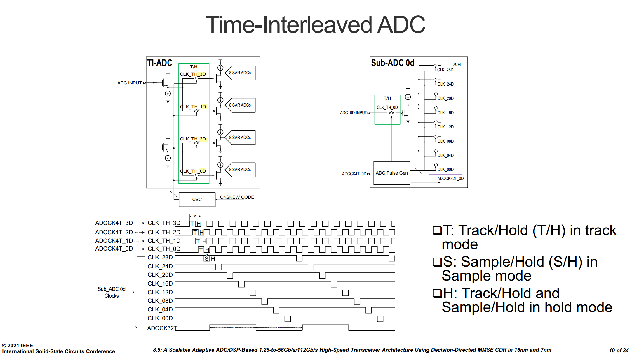
64Gb/s Clock Generation
D. Xu et al., "8.5 A Scalable Adaptive ADC/DSP-Based 1.25-to-56Gbps/112Gbps High-Speed Transceiver Architecture Using Decision-Directed MMSE CDR in 16nm and 7nm," 2021 IEEE International Solid-State Circuits Conference (ISSCC), San Francisco, CA, USA, 2021, pp. 134-136 [https://sci-hub.ru/10.1109/ISSCC42613.2021.9366063]
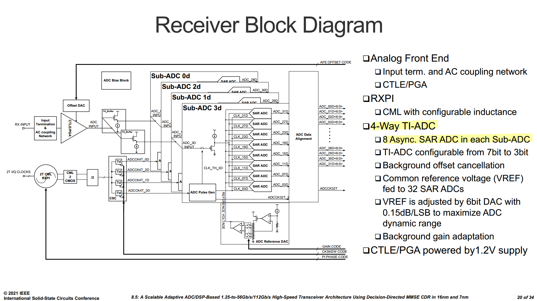
4x8 Time Interleaving w/ 25% duty cycle for input tracking


Ensure nominal order by masking some edges
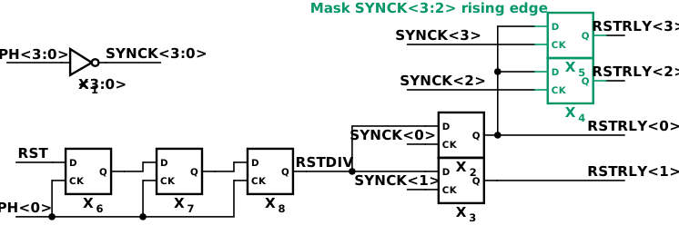

ring counter for generating SAH clock
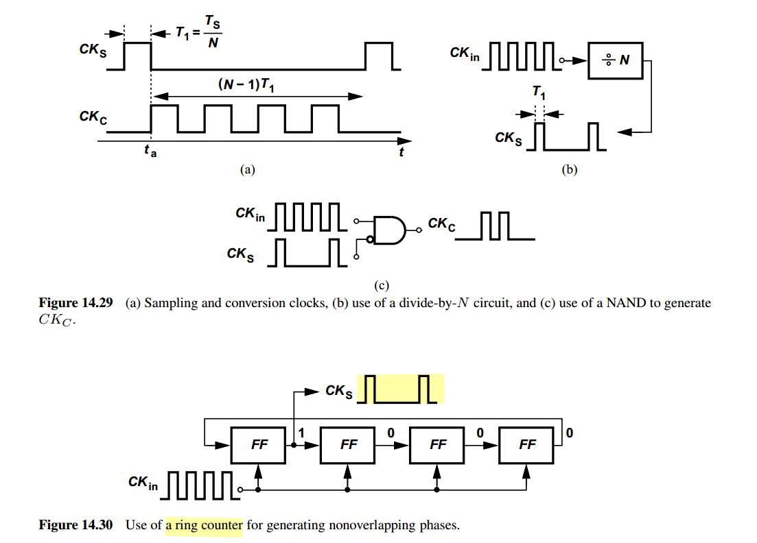

all FFs initialized to 0
J. Im et al., "6.1 A 112Gb/s PAM-4 Long-Reach Wireline Transceiver Using a 36-Way Time-Interleaved SAR-ADC and Inverter-Based RX Analog Front-End in 7nm FinFET," 2020 IEEE International Solid-State Circuits Conference - (ISSCC), San Francisco, CA, USA, 2020, pp. 116-118 [https://sci-hub.ru/10.1109/ISSCC19947.2020.9063081]
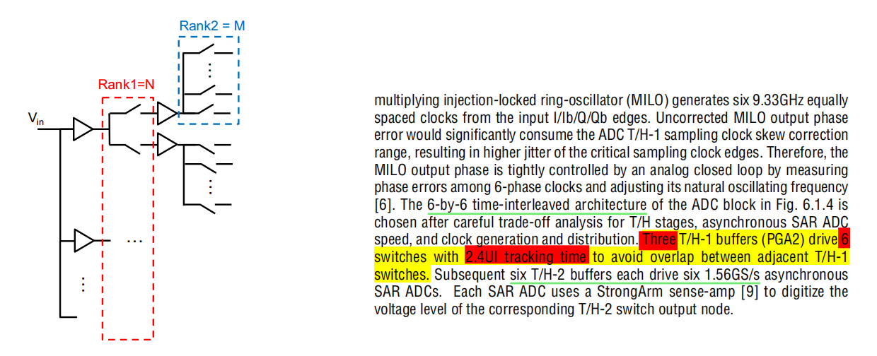

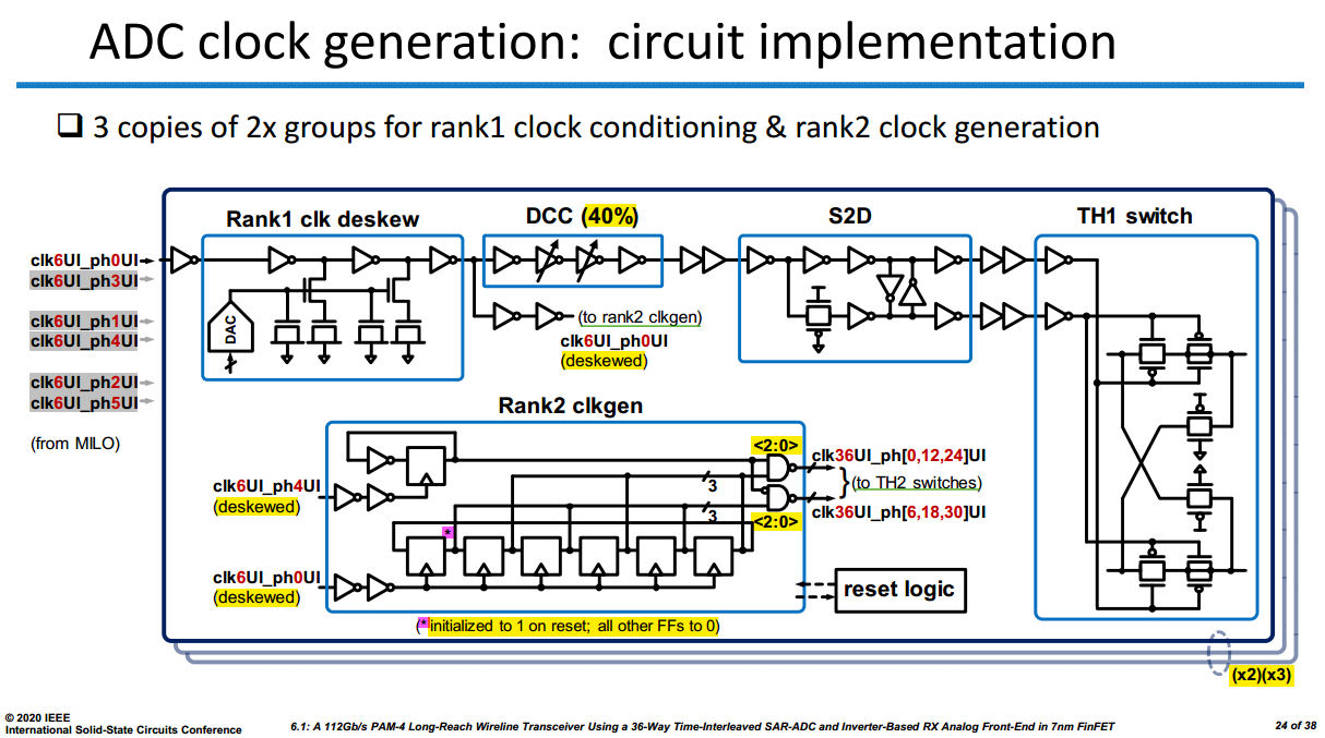
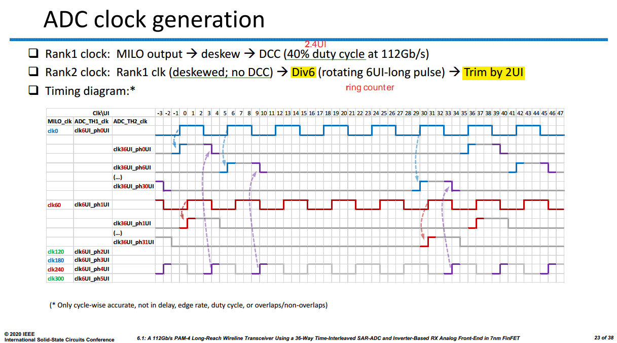
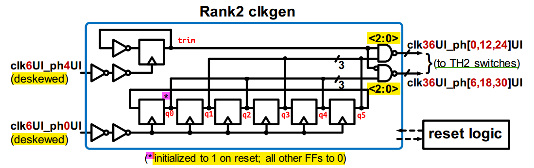

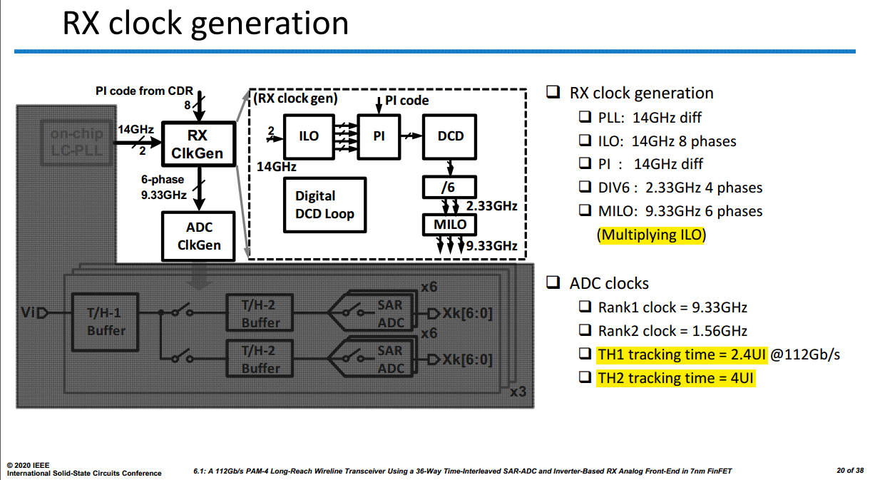
128Gb/s Clock Generation
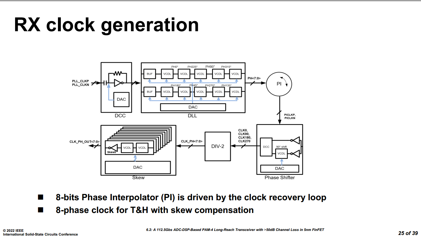
Z. Guo et al., "A 112.5Gb/s ADC-DSP-Based PAM-4 Long-Reach Transceiver with >50dB Channel Loss in 5nm FinFET," 2022 IEEE International Solid-State Circuits Conference (ISSCC), San Francisco, CA, USA, 2022 [https://sci-hub.st/10.1109/ISSCC42614.2022.9731650]
P. Liu et al., "A 128Gb/s ADC/DAC Based PAM-4 Transceiver with >45dB Reach in 3nm FinFET," 2025 Symposium on VLSI Technology and Circuits (VLSI Technology and Circuits), Kyoto, Japan, 2025

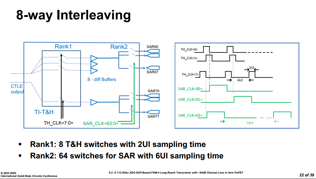

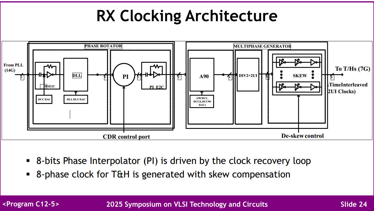

224Gb/s Clock Generation
M. Gambhir et al., "A 2.05pJ/bit, 212.5Gbps DSP Based Transceiver with 55dB Reach in 3nm FinFET," 2026 IEEE/JSAP Symposium on VLSI Technology and Circuits (VLSI Technology and Circuits), Honolulu, HI, USA, 2026, pp. 1-3, doi: 10.1109/VLSITechnologyandCir65830.2026.11577411.
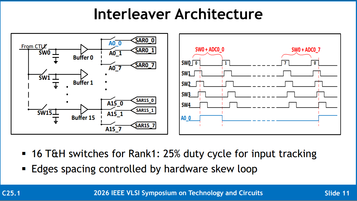
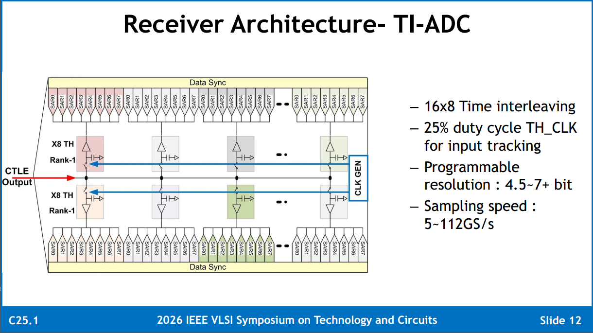
4UI track, 12UI hold in TAH
ADC Data Alignment
Gain Kim, 2023. Equalization, Architecture, and Circuit Design for High-Speed Serial Link Receiver [www.theise.org/...]
Calibration Techniques
M. Guo, J. Mao, S. -W. Sin, H. Wei and R. P. Martins, "A 5 GS/s 29 mW Interleaved SAR ADC With 48.5 dB SNDR Using Digital-Mixing Background Timing-Skew Calibration for Direct Sampling Applications," in IEEE Access, vol. 8, pp. 138944-138954, 2020, doi: 10.1109/ACCESS.2020.3012699 [https://ieeexplore.ieee.org/stamp/stamp.jsp?tp=&arnumber=9151956]
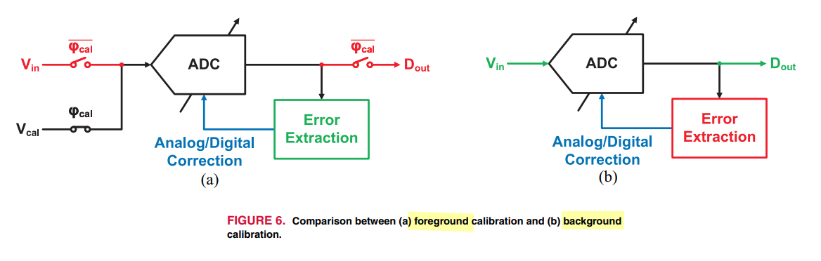
Autocorrelation-based Skew Calibration
S. Chen, L. Wang, H. Zhang, R. Murugesu, D. Dunwell, A. Chan Carusone, “All-Digital Calibration of Timing Mismatch Error in Time-Interleaved Analog-to-Digital Converters,” IEEE Transactions on VLSI Systems, Sept. 2017. [PDF, slides]
B. Razavi, "Problem of timing mismatch in interleaved ADCs," Proceedings of the IEEE 2012 Custom Integrated Circuits Conference, San Jose, CA, USA, 2012 [pdf]
Binary-Search Calibration Method & its limitations
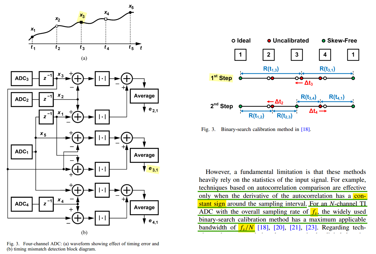
M. Gu, Y. Tao, X. He, Y. Zhong, L. Jie and N. Sun, "A 1-GS/s 11-b Time-Interleaved SAR ADC With Robust, Fast, and Accurate Autocorrelation-Based Background Timing-Skew Calibration," in IEEE Journal of Solid-State Circuits, vol. 60, no. 2, pp. 421-431, Feb. 2025
—. "Timing-Skew Calibration Techniques in Time-Interleaved ADCs," in IEEE Open Journal of the Solid-State Circuits Society, vol. 5, pp. 1-10, 2025 [https://ieeexplore.ieee.org/stamp/stamp.jsp?tp=&arnumber=10804623]
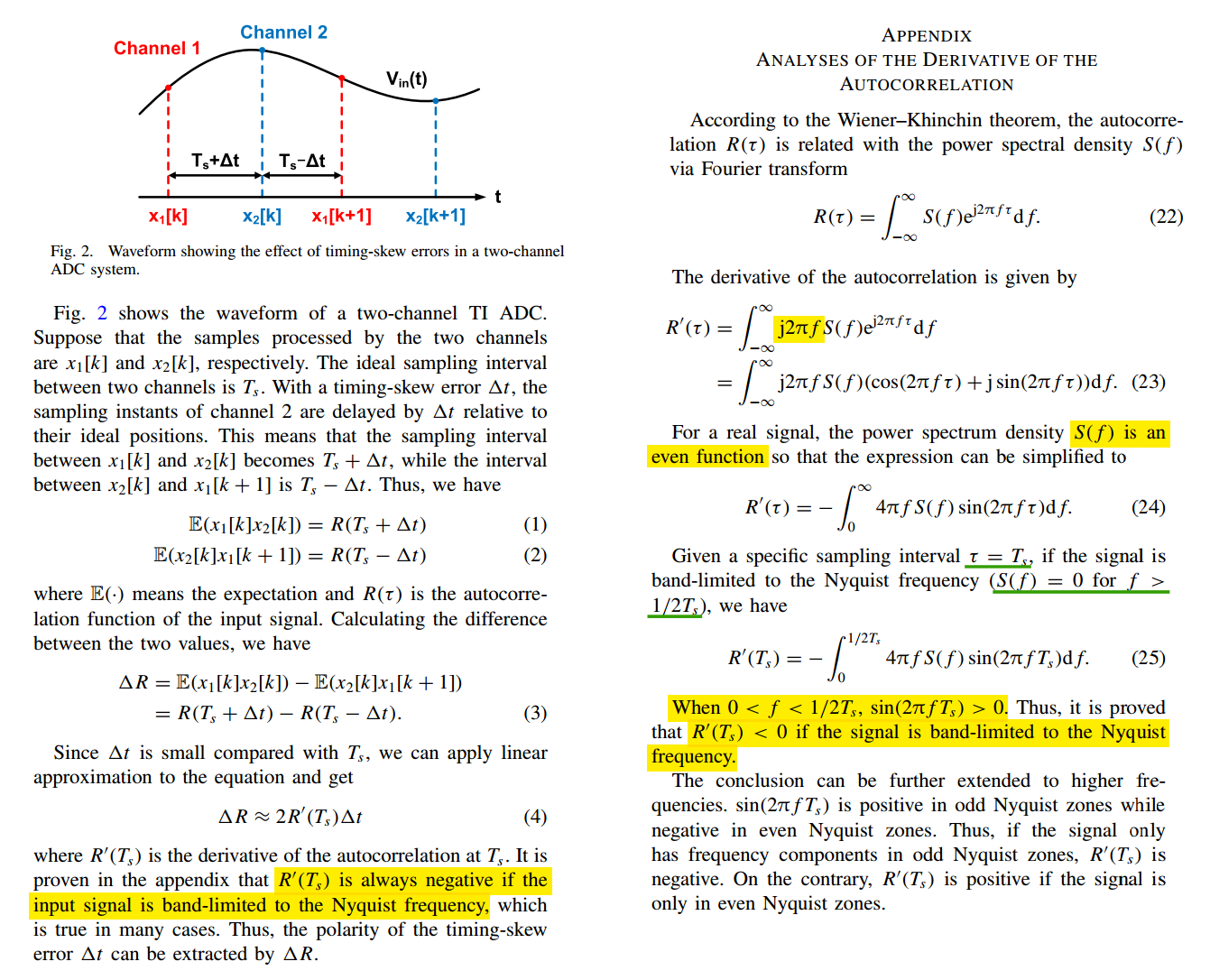
An autocorrelation-based background timing-skew calibration method, which uses the correlations between adjacent channels to extract timing-skew errors, which relaxes the input bandwidth limitation up to the Nyquist frequency
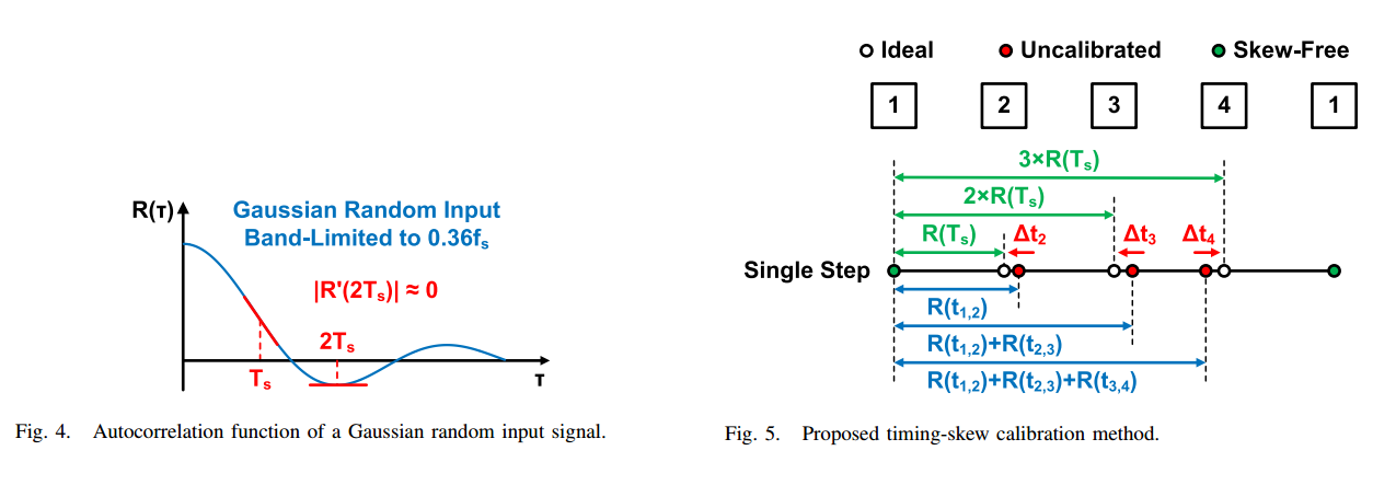
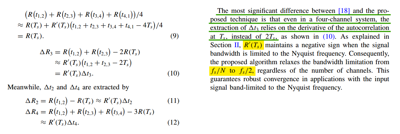
Analyses Of The Derivative of The Autocorrelation
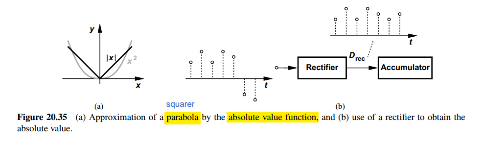
MAD (Mean Absolute Difference) vs. correlation
H. Wei, P. Zhang, B. Datta Sahoo and B. Razavi, "An 8-Bit 4-GS/s 120-mW CMOS ADC," Proceedings of the IEEE 2013 Custom Integrated Circuits Conference, San Jose, CA, USA, 2013 [pdf]
—, "An 8 Bit 4 GS/s 120 mW CMOS ADC," in IEEE Journal of Solid-State Circuits, vol. 49, no. 8, pp. 1751-1761, Aug. 2014 [pdf]
M. Gu, Y. Tao, X. He, Y. Zhong, L. Jie and N. Sun, "A 1-GS/s 11-b Time-Interleaved SAR ADC With Robust, Fast, and Accurate Autocorrelation-Based Background Timing-Skew Calibration," in IEEE Journal of Solid-State Circuits, vol. 60, no. 2, pp. 421-431, Feb. 2025
TODO 📅
approximate the absolute value operation by a squaring function
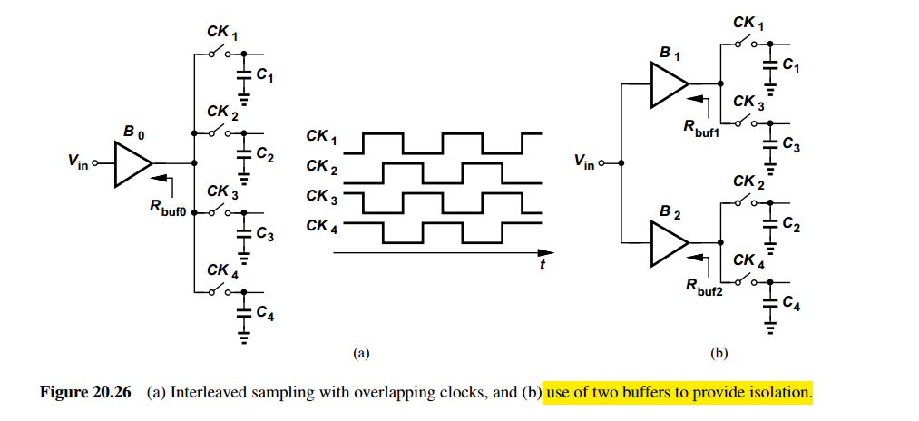
Overlapping versus Non-overlapping track time
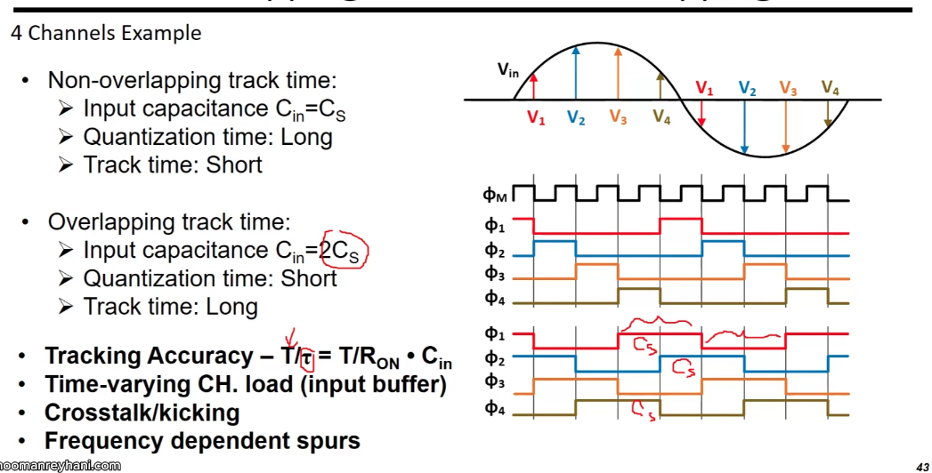
tracking accuracy stay same, Cin (2Cs) counteract the longer tracking
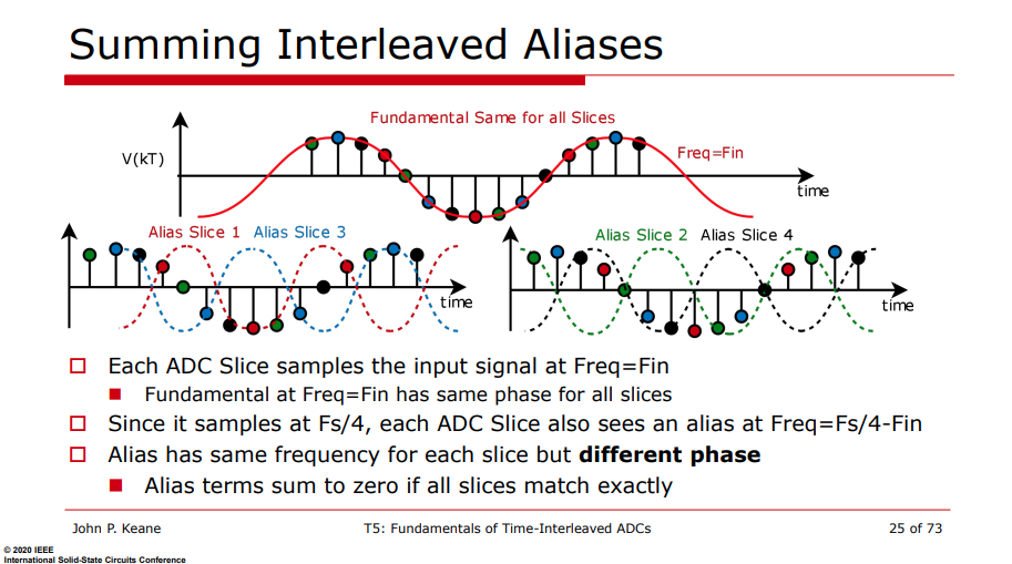
Summing Interleaved Alias
The sampling function - impulse train is \[ s(t) = \sum_{n=-\infty}^{\infty}\left[ \delta(t-n4T_s) + \delta(t-n4T_s-T_s) + \delta(t-n4T_s-2T_s) + \delta(t-n4T_s-3T_s)\right] \]
Its Fourier transform is \[\begin{align} S(f) &= \frac{2\pi}{4T}\sum_{k=-\infty}^{\infty}\left[\delta(f-k\frac{f_s}{4}) + e^{-j2\pi f\cdot T_s}\delta(f-k\frac{f_s}{4}) + e^{-j2\pi f\cdot 2T_s}\delta(f-k\frac{f_s}{4}) + e^{-j2\pi f\cdot 3T_s}\delta(f-k\frac{f_s}{4}) \right] \\ &= \frac{2\pi}{4T}\sum_{k=-\infty}^{\infty}\left(1+e^{-j2\pi\frac{f}{f_s}} + e^{-j4\pi\frac{f}{f_s}} + e^{-j6\pi\frac{f}{f_s}} \right) \delta(f-k\frac{f_s}{4}) \\ &= \frac{2\pi}{4T}\sum_{k=-\infty}^{\infty}\left(1+e^{-jk\frac{\pi}{2}} + e^{-jk\pi} + e^{-jk\frac{3\pi}{2}} \right) \delta(f-k\frac{f_s}{4}) \end{align}\]
We define \(M[k] = 1+e^{-jk\frac{\pi}{2}} + e^{-jk\pi} + e^{-jk\frac{3\pi}{2}}\), which is periodic, i.e. \(M[k]=M[k+4]\) \[ M[k]=\left\{ \begin{array}{cl} 4 & : \ k = 4m \\ 0 & : \ k=4m+1 \\ 0 & : \ k=4m+2 \\ 0 & : \ k=4m+3 \\ \end{array} \right. \]
That is \[ S(f) = \frac{2\pi}{T}\sum_{k=-\infty}^{\infty} \delta(f-kf_s) \]
Alias has same frequency for each slice but different phase: Alias terms sum to zero if all slices match exactly
Random Chopping in TI-ADC
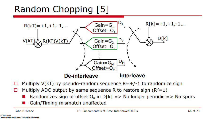
\[ D_n(kT) = (G_n R(kT) V(kT) + O_n)R(kT)= C_n V(kT) + R(kT)O_n \]
ADC buffers & memory effect
Y. Shifman, Y. Krupnik, U. Virobnik, A. Khairi, Y. Sanhedrai and A. Cohen, "A 1.64mW Differential Super Source-Follower Buffer with 9.7GHz BW and 43dB PSRR for Time-Interleaved ADC Applications in 10nm," 2019 IEEE Asian Solid-State Circuits Conference (A-SSCC), Macau, Macao, 2019 [pdf]
E. -H. Chen et al., "7.1 A 212.5Gb/s DSP-Based PAM-4 Transceiver with 50dB Loss Compensation for Large AI System Interconnects in 4nm FinFET," 2025 IEEE International Solid-State Circuits Conference (ISSCC), San Francisco, CA, USA, 2025
N. G. Jayaraman, “High speed buffering for time-interleaved ADCs with reduced ISI and increased voltage gain,” WO Patent 2018164928 A1, Sep. 13, 2018. [Online]. Available: [https://patents.google.com/patent/WO2018164928A1]
TODO 📅
DNL/INL Benefit
Each sub-ADC has its own physical capacitor array, so each slice has its own independent, zero-mean mismatch error
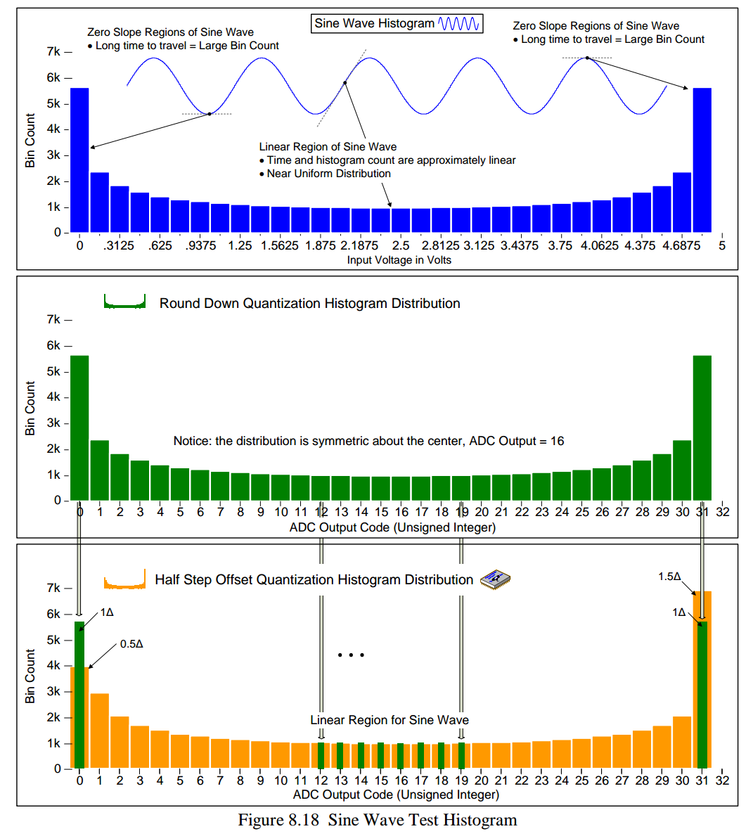
Because the sub-ADC are sampled round-robin, a busy input signal visits all \(N\) sub-ADC with equal probability over the whole input range. The transfer curve that the composite output presents is therefore the ensemble average \[ e_{\mathrm{eff}}(k) = \frac{1}{N}\sum_{i=1}^{N} e_i(k) \quad\Rightarrow\quad \sigma\!\left\{e_{\mathrm{eff}}(k)\right\} = \frac{\sigma\{e_i(k)\}}{\textcolor{red}{\sqrt{N}}} \] the measured static DNL/INL genuinely improves by \(\sqrt{N}\) at code-density (histogram) test
The composite result \[ \boxed{\sigma_{DNL,\max}^{TI} = \frac{\sigma_{\text{sub},DNL}}{\sqrt{N}}, \qquad \sigma_{INL,\max}^{TI} = \frac{\sigma_{\text{sub},INL}}{\sqrt{N}}} \] where \(N\) is channel number
Conventional binary array sub-SARADC \[ \sigma_{DNL,\max}=\sqrt{2^n-1}\,\frac{\sigma_u}{C_u}\,[\mathrm{LSB}], \qquad \sigma_{INL,\max}=\frac{\sqrt{2^n}}{2}\,\frac{\sigma_u}{C_u}\,[\mathrm{LSB}] \] VCM-based (\(n-1\) bit array) sub-SARADC
In a VCM-based (top-plate-sampled, tri-level) SAR, the MSB decision needs no capacitor switching at all — it's a direct comparison against \(V_{CM}\) \[ \sigma^{VCM}_{DNL,\max} = \sqrt{2^{n-1}-1}\,\frac{\sigma_u}{C_u}, \qquad \sigma^{VCM}_{INL,\max} = \frac{\sqrt{2^{n-1}}}{2}\,\frac{\sigma_u}{C_u} \qquad \text{at } k=2^{n-2},\,3\cdot 2^{n-2} \]
reference
Poulton, Ken. ISSCC2009 "Time-Interleaved ADCs, Past and Future" (slides)
—. CICC2010 "GHz ADCs: From Exotic to Mainstream", tutorial session, (slides)
—. ISSCC2015 "Interleaved ADCs Through the Ages", (slides)
ISSCC2015 F1: High-Speed Interleaved ADCs
Ron Kapusta, Analog Devices, CICC2015 ED007: SAR ADCs in parallel [time-interleaved] converter arrays
Samuel Palermo, ISSCC 2018 T10: ADC-Based Serial Links: Design and Analysis
Ewout Martens. ESSCIRC 2019 Tutorials: Advanced Techniques for ADCs for 5G Massive MIMO [https://youtu.be/7hYichGGU6k]
Yohan Frans, CICC2019 ES3-3- "ADC-based Wireline Transceivers" [pdf]
John P. Keane, ISSCC2020 T5: "Fundamentals of Time-Interleaved ADCs"
Athanasios Ramkaj. January 26, 2022, IEEE SSCS Santa Clara Valley Section Technical Talk: Design Considerations Towards Optimal High-Resolution Wide-Bandwidth Time-Interleaved ADCs [video] [slides]
V. Chen, "Tutorial: High-Speed Analog-to-Digital Converters," 2025 IEEE International Solid-State Circuits Conference (ISSCC), San Francisco, CA, USA, 2025, pp. 1-1, doi: 10.1109/ISSCC49661.2025.11076112.
Ahmed M. A. Ali 2016, "High Speed Data Converters"
Razavi, B. (2025). Analysis and design of data converters. Cambridge University Press.
S. Jang, J. Lee, Y. Choi, D. Kim, and G. Kim, "Recent advances in ultra-high-speed wireline receivers with ADC-DSP-based equalizers," IEEE Open Journal of the Solid-State Circuits Society (OJ-SSCS), vol. 4, pp. 290-304, Nov. 2024.
Yida Duan. Design Techniques for Ultra-High-Speed Time-Interleaved Analog-to-Digital Converters (ADCs) [http://www2.eecs.berkeley.edu/Pubs/TechRpts/2017/EECS-2017-10.pdf]
Preview Lecture #1 - "Extreme SAR ADCs" Online Course (2024) - Prof. Chi-Hang Chan (U. of Macau) [https://youtu.be/rgMRL4QZ-wA]
oscarmattia. Data Converter Toolbox [https://github.com/oscarmattia/data_converter_toolbox]