ADC in Instrument & Measurement (I&M)
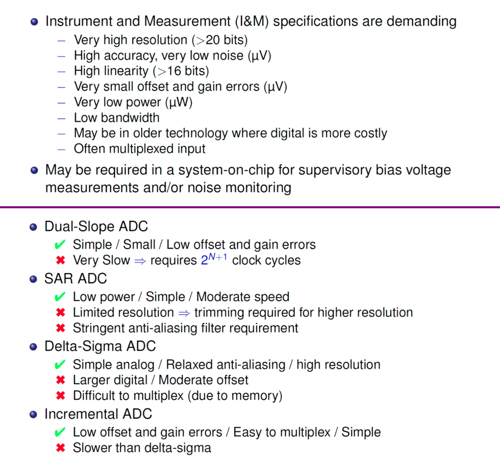
Dual Slope ADC
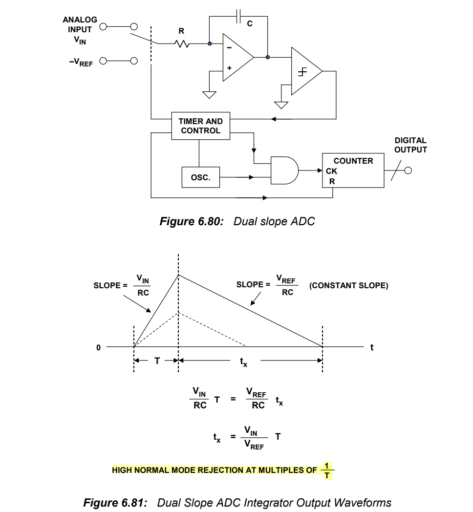
\[ V_{IN} = \frac{V_{REF}}{T}t_\text{x} = \frac{V_{REF}}{2^N}\cdot 2^{N_\text{x}} \]
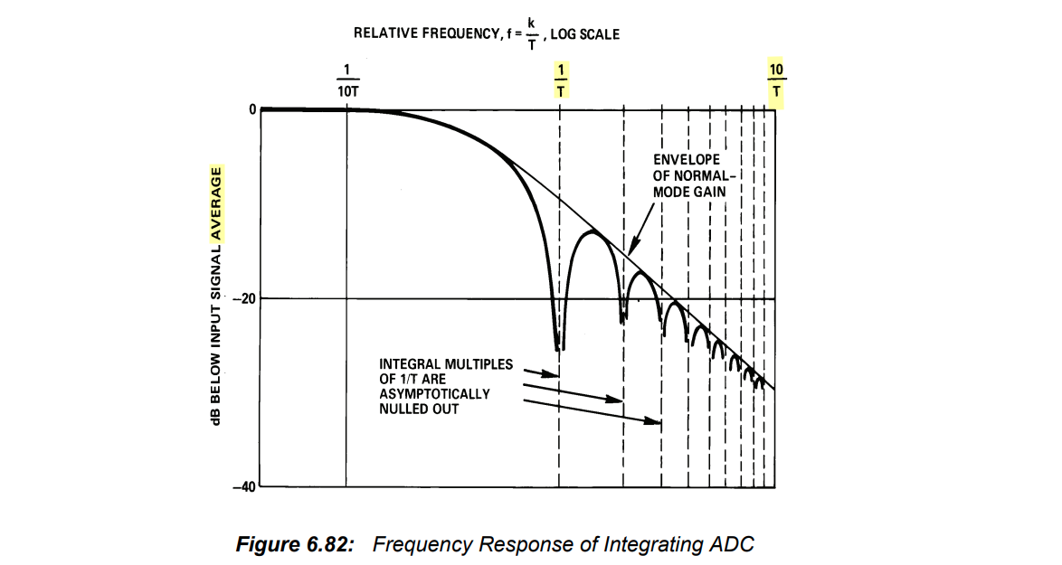
Normal Mode Rejection
a high normal mode rejection ratio (NMRR) for input noise at line frequency
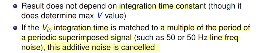
Conversion accuracy is independent of both the capacitance and the clock frequency, because they affect both the up-slope and the down-slope by the same ratio
The fixed input signal integration period results in rejection of noise frequencies on the analog input that have periods that are equal to or a sub-multiple of the integration time \(T\)
Interference signals with frequencies at integral multiples of the integration period are, theoretically, completely removed, since the average value of a sine wave of frequency (\(1/T\)) averaged over a period (\(T\)) is zero
Linear Circuit Design Handbook, 2008 [https://www.analog.com/media/en/training-seminars/design-handbooks/Basic-Linear-Design/Chapter6.pdf]
Precision Analog Front Ends with Dual Slope ADC [https://ww1.microchip.com/downloads/aemDocuments/documents/APID/ProductDocuments/DataSheets/21428e.pdf]
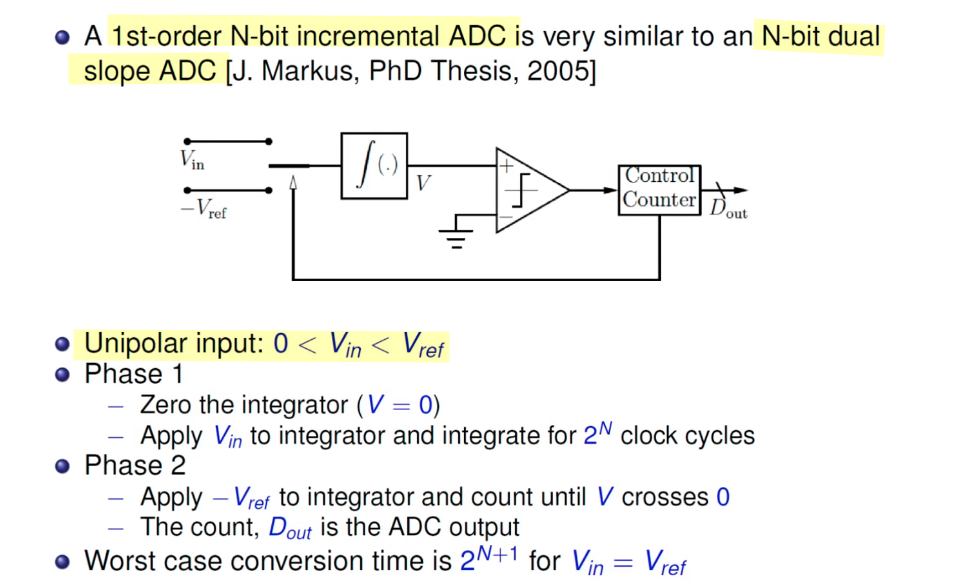
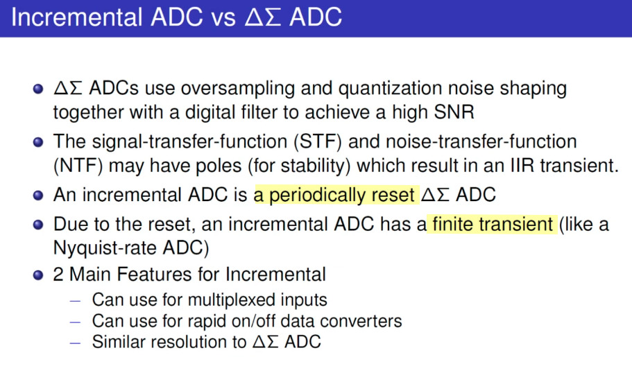
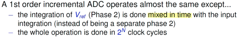
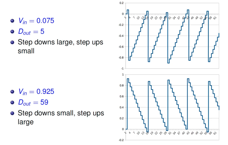
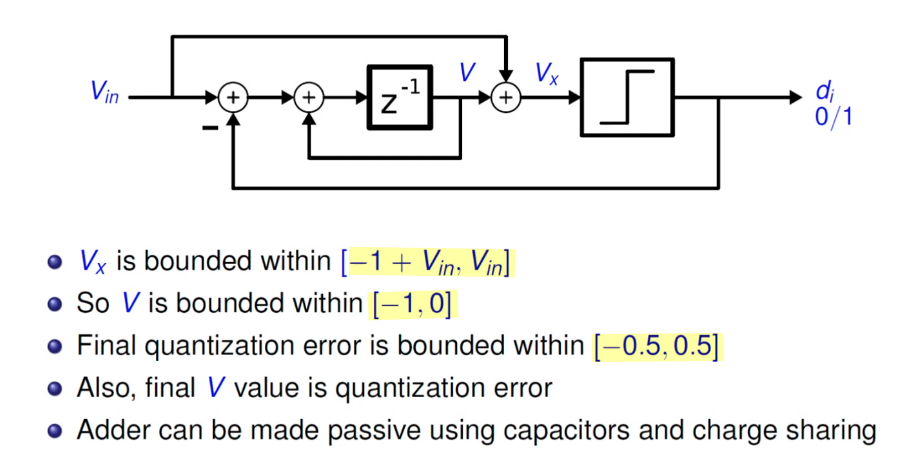
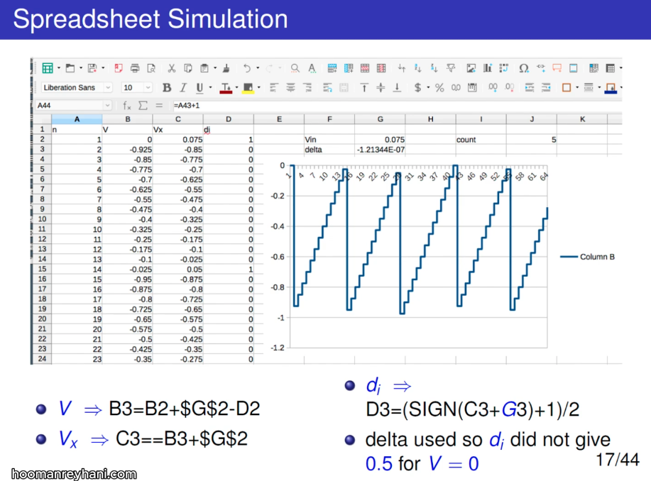
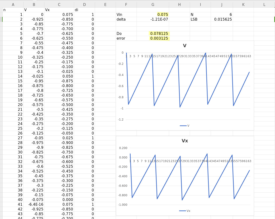
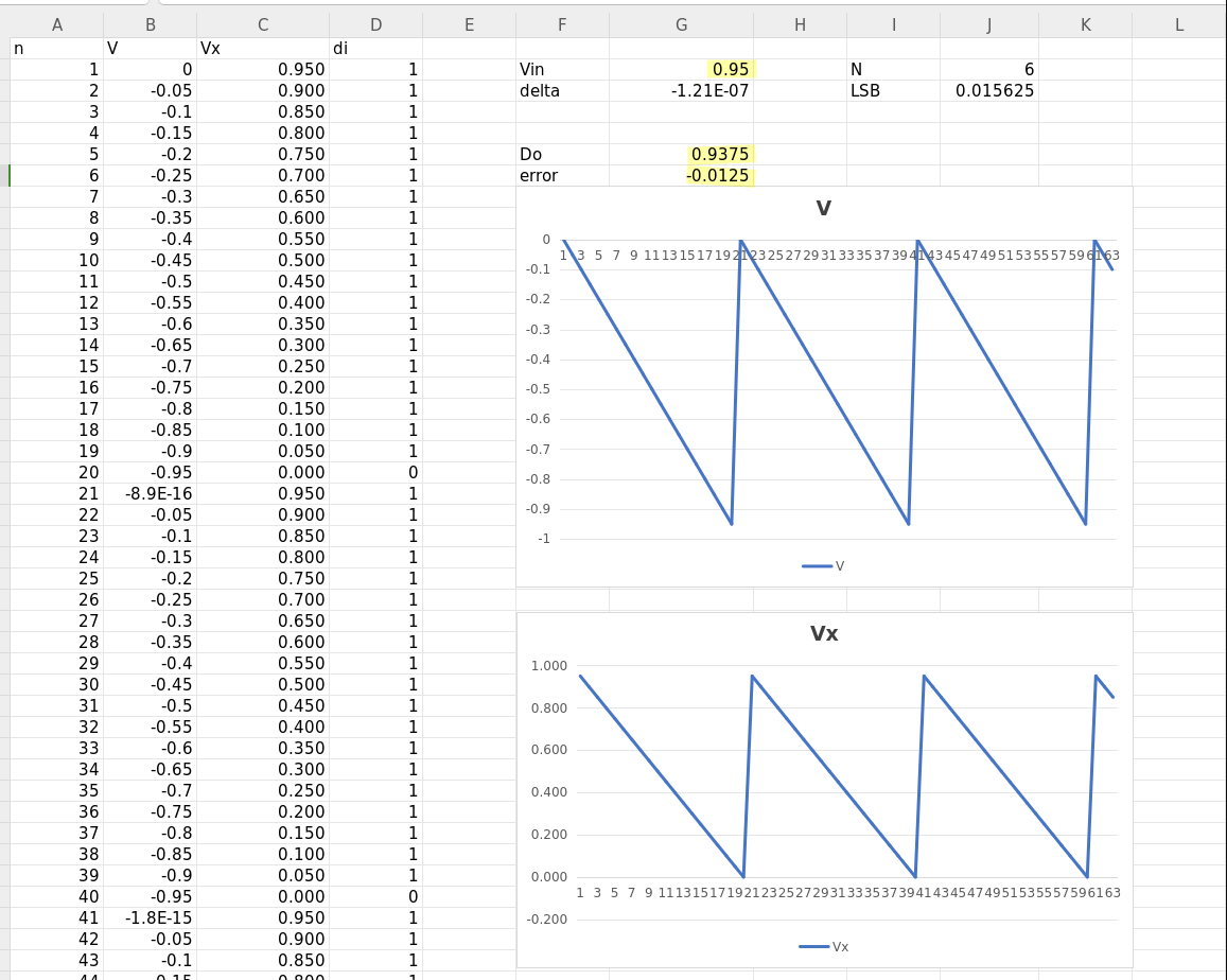
Incremental ADC
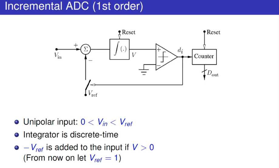
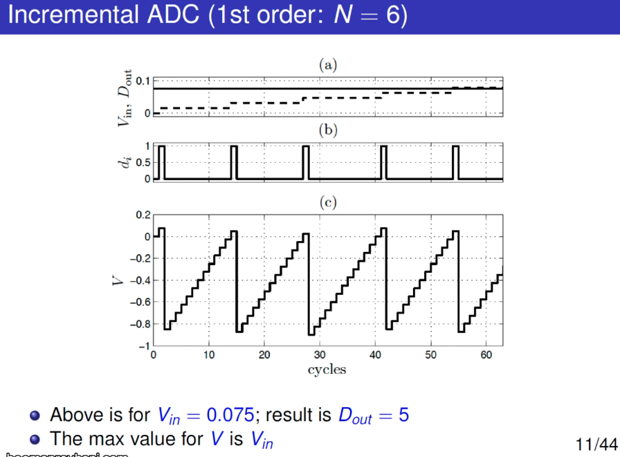
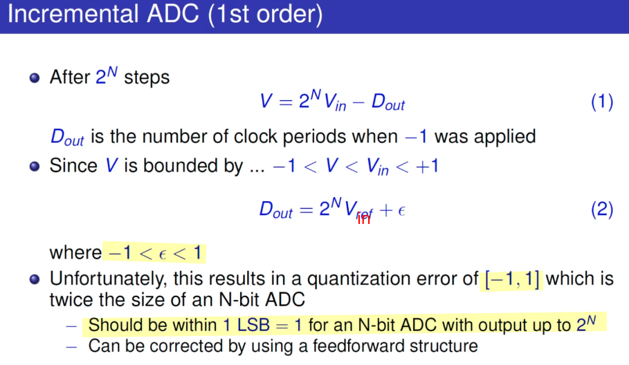
\[\begin{align} V &= 2^N V_\text{in} - D_\text{out}V_\text{ref} \\ D_\text{out} \frac{V_\text{ref}}{2^N} &= V_\text{in} - \frac{V}{2^N} \end{align}\]
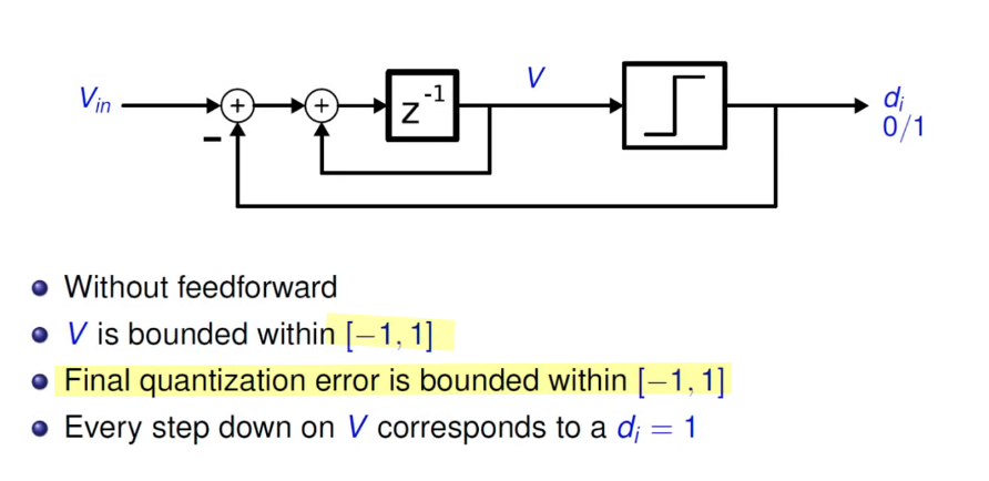
feedforward structure
??? TODO 📅
reference
David Johns (University of Toronto) "Oversampled Data Converters" Course (2019) [https://youtu.be/qIJ2LORYmyA]
Maurits Ortmanns , Paul Kaesser , Johannes Wagner (Dec 2025). Incremental Delta-Sigma ADCs Theory, Architectures and Design - Theory, Architectures and Design