Electricity & Magnetism
magnetic field (magnetic flux density, \(B\)), is the tesla (symbol: \(T\)), defined as one weber per square meter (\(Wb/m^2\))
Magnetic flux \(\Phi_B\) measures the total magnetic field (\(B\)) passing through a given surface area (\(A\)), representing the number of field lines penetrating that area. Measured in Webers (\(Wb\)),
Vector Calculus
3Blue1Brown, Divergence and curl: The language of Maxwell's equations, fluid flow, and more [https://youtu.be/rB83DpBJQsE]
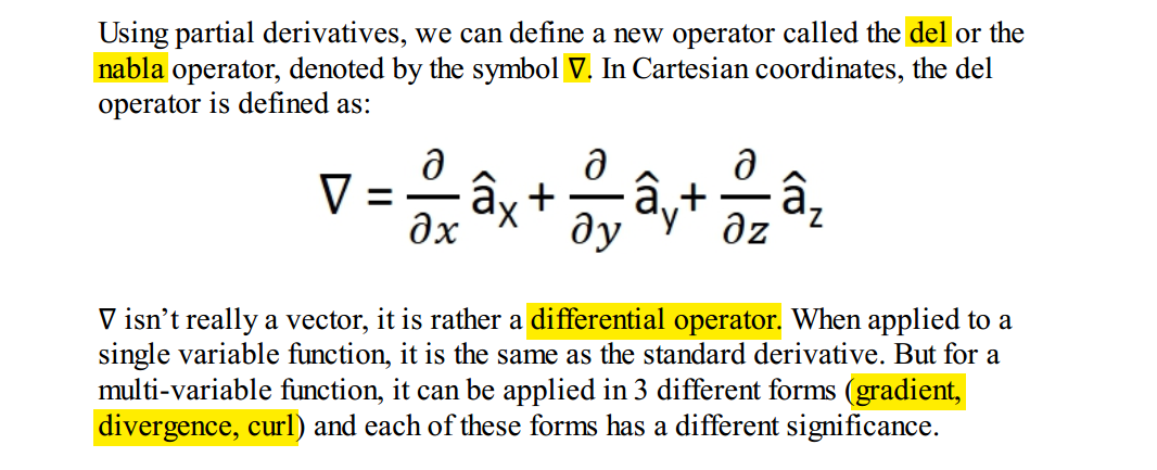
Gradient
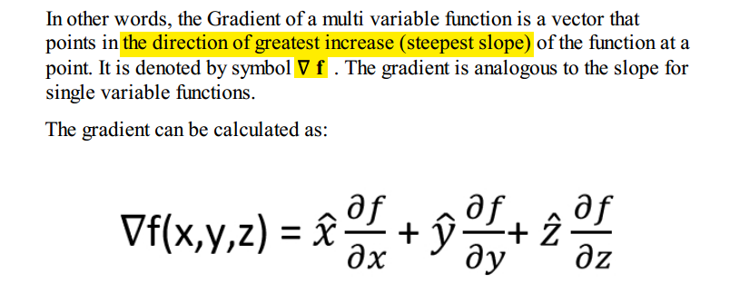
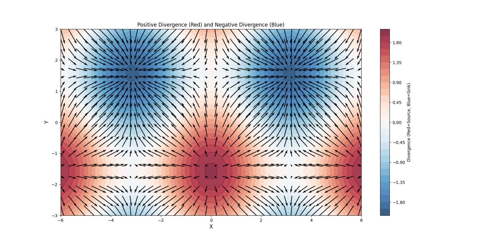
Divergence
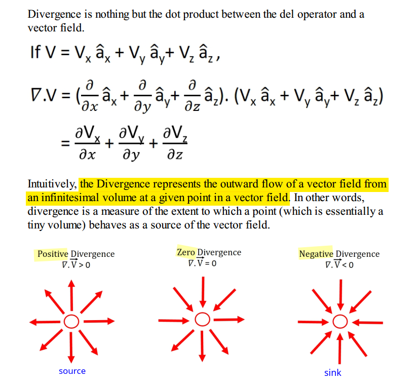
1 | # https://share.google/aimode/l3lNa2MRAOG8hkpOc |
Curl
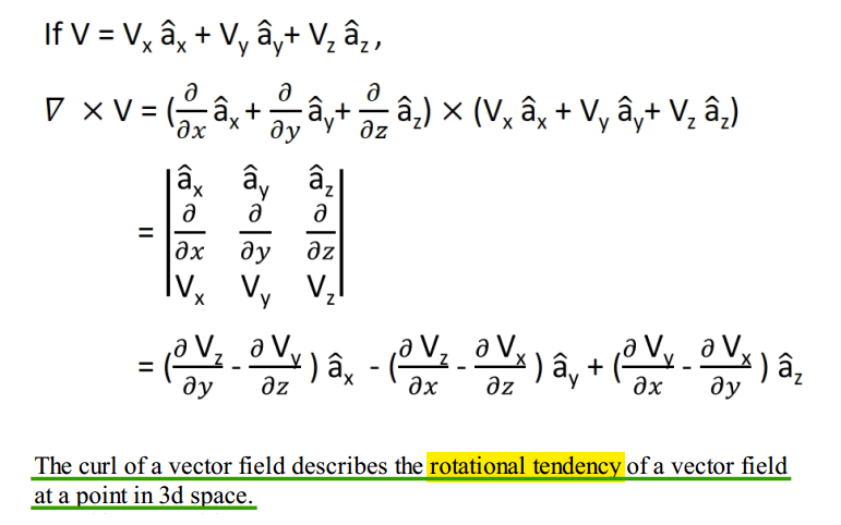
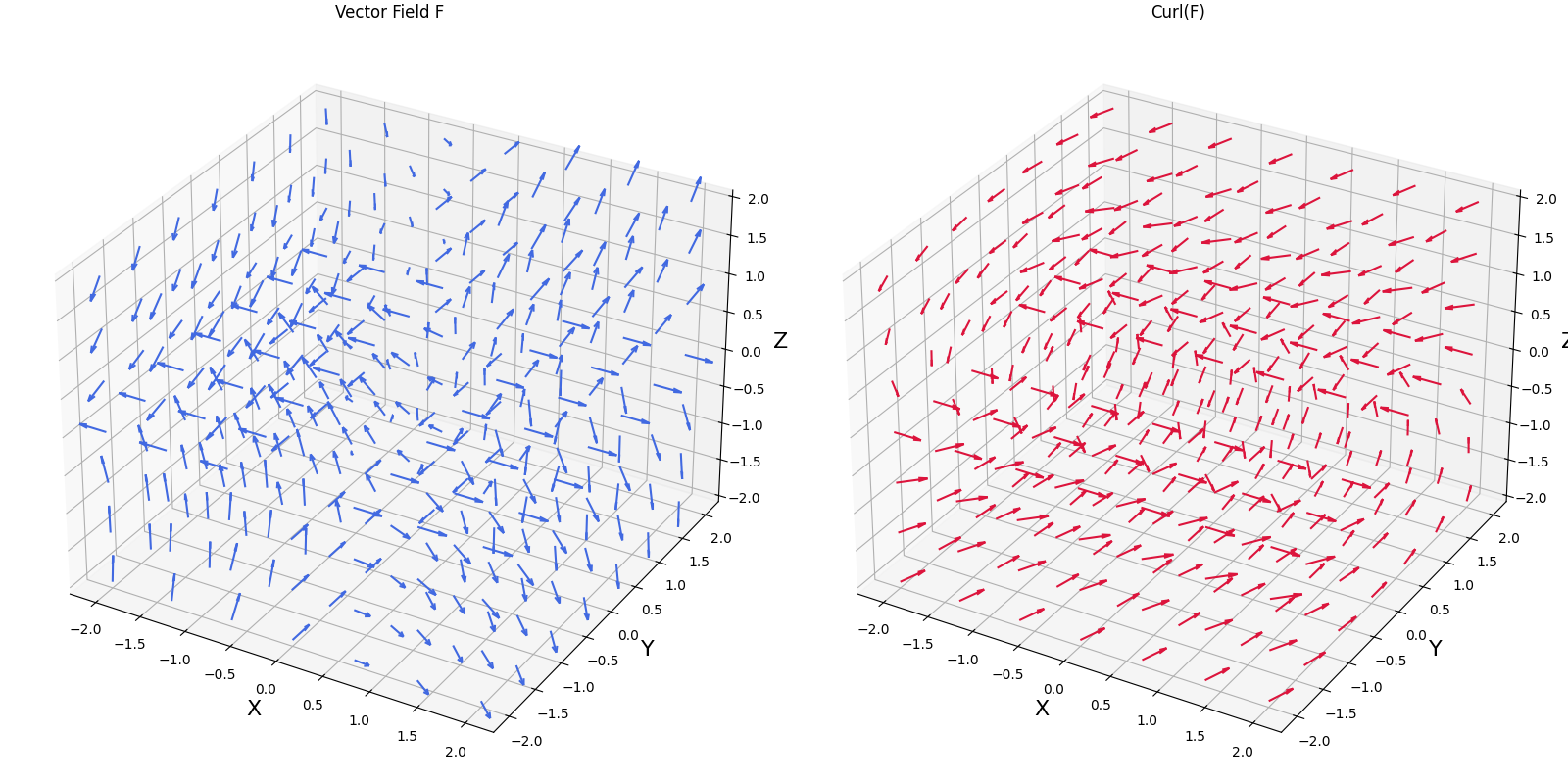
1 | # https://share.google/aimode/hWb3cR4vCBoWV4Moi |
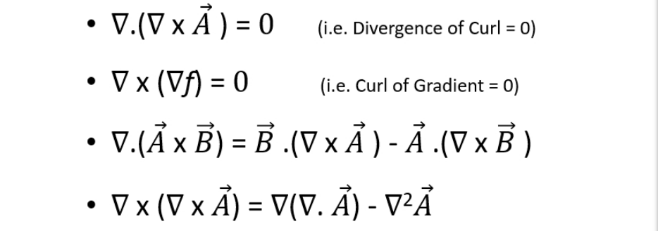
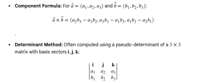
cross product [Google AI Mode]
Divergence Theorem (Gauss's Theorem)
surface integral -> volume integral \[ \oint_S \vec{F} \cdot d\vec{S} = \int_V (\nabla \cdot \vec{F}) dv \]
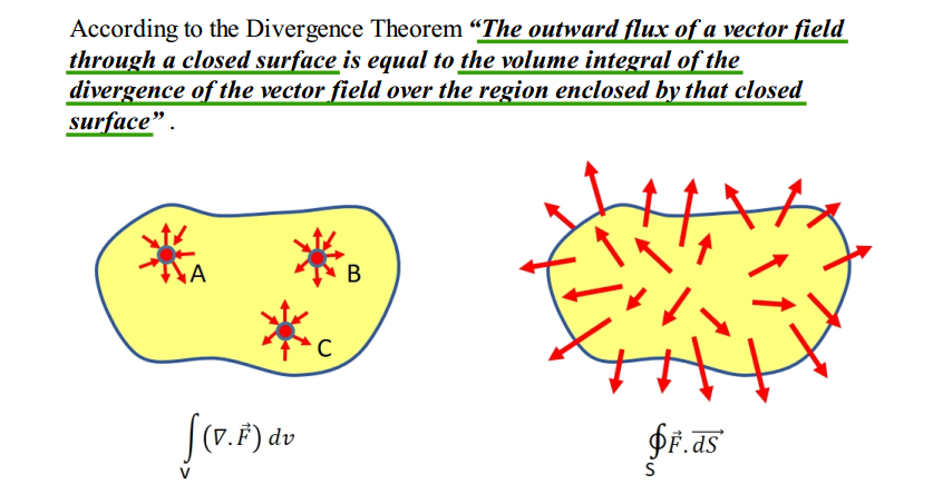
Divergence theorem is only applicable to closed surfaces

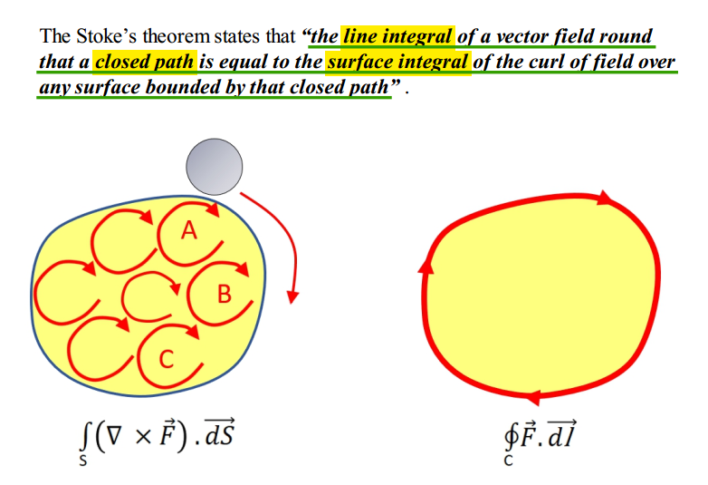
Stoke's theorem
line integral -> surface inegral \[ \oint_{c} \vec{F} \cdot \vec{\mathrm{d}l} = \int_{s} (\nabla \times \vec{F}) \cdot \vec{\mathrm{d}S} \]
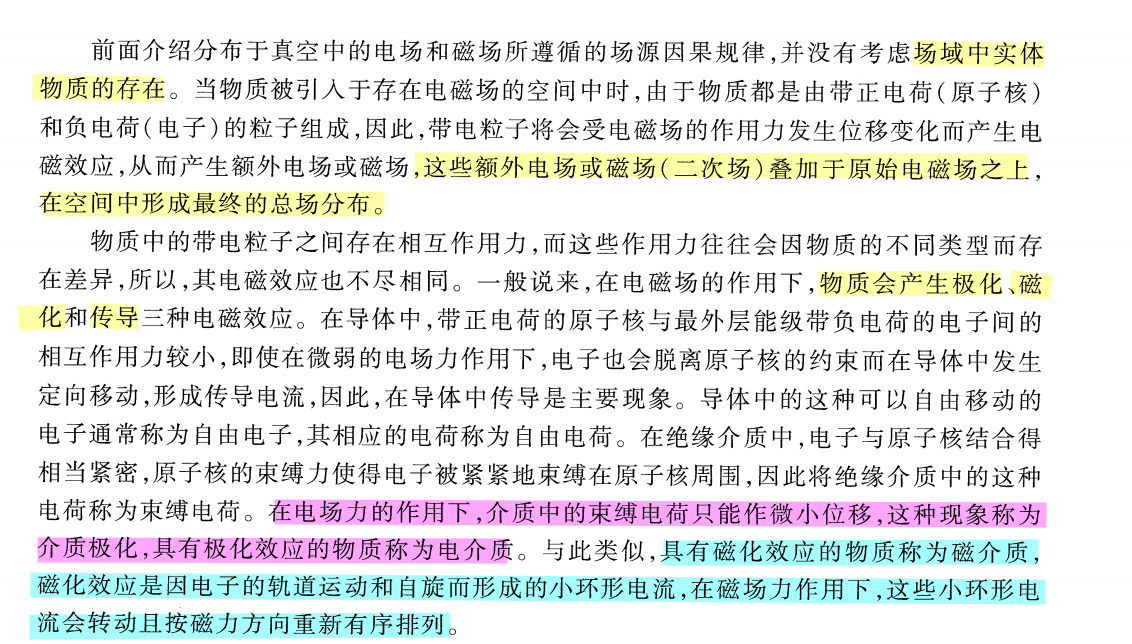
Polarization \(\mathbf P\) & magnetization \(\mathbf M\)
Electric Fields in Matter & Magnetic Fields in Matter
TODO 📅
Electric Fields
Electric field intensity \(\mathbf E\) & Electric flux density \(\mathbf D\)
\[ \boxed{ \underbrace{\varepsilon_0\mathbf E}_{\text{contains free + bound charge effects}} + \underbrace{\mathbf P}_{\text{cancels bound-charge divergence}} = \underbrace{\mathbf D}_{\text{free-charge Gauss law}} }. \] Start from Gauss’s law for the actual electric field: \[ \nabla\cdot(\varepsilon_0\mathbf E) = \rho_{\text{free}}+\rho_{\text{bound}}. \] Polarization satisfies \[ \rho_{\text{bound}}=-\nabla\cdot\mathbf P. \] Therefore, \[ \nabla\cdot(\varepsilon_0\mathbf E) = \rho_{\text{free}}-\nabla\cdot\mathbf P. \] Move the polarization term to the left: \[ \nabla\cdot(\varepsilon_0\mathbf E+\mathbf P) = \rho_{\text{free}}. \] Define \[ \mathbf D=\varepsilon_0\mathbf E+\mathbf P. \]
Electric field intensity \(\mathbf E\)
Gauss's law for \(\mathbf E\) is \[ \boxed{ \nabla\cdot\mathbf E = \frac{\rho_{\text{total}}}{\varepsilon_0} } \] where \[ \rho_{\text{total}} = \rho_{\text{free}}+\rho_{\text{bound}}. \] Therefore, \(\mathbf E\) is determined by all charges:
- externally supplied free charges,
- polarization-induced bound charges.
In integral form, \[ \oint_S \mathbf E\cdot d\mathbf S = \frac{Q_{\text{total,enclosed}}}{\varepsilon_0}. \]
Electric flux density \(\mathbf D\)
Gauss's law for \(\mathbf D\) is \[ \boxed{ \nabla\cdot\mathbf D=\rho_{\text{free}} } \] or \[ \boxed{ \oint_S\mathbf D\cdot d\mathbf S = Q_{\text{free,enclosed}} } \] Thus, \(\mathbf D\) is constructed so that dielectric bound charge is absorbed into the constitutive relation \[ \mathbf D=\varepsilon_0\mathbf E+\mathbf P. \] It therefore relates directly only to free charge
Gauss's law for \(\mathbf{E}\) & Gauss's law for \(\mathbf{D}\)
\[ \boxed{ \begin{aligned} \nabla\cdot\mathbf E &=\frac{\rho_{\text{total}}}{\varepsilon_0}, \\[4pt] \nabla\cdot\mathbf D &=\rho_{\text{free}}. \end{aligned} } \]
So when a textbook writes \[ \oint_S\mathbf D\cdot d\mathbf S = \int_V\rho_v\,dV, \] the symbol \(\rho_v\) normally means \[ \boxed{\rho_v=\rho_{v,\text{free}}}. \] But when it writes \[ \oint_S\mathbf E\cdot d\mathbf S = \frac{1}{\varepsilon_0}\int_V\rho_v\,dV, \] then \(\rho_v\) means the total volume-charge density, unless the context explicitly assumes vacuum or no polarization
Magnetostatics
Magnetostatics is the study of magnetic fields in systems where the currents are steady (not changing with time)

Relationship between \(\mathbf B\) and \(\mathbf H\)
The central distinction is \[ \boxed{ \mathbf H\text{ tracks the free-current excitation, while } \mathbf B\text{ is the resulting total magnetic flux density.} } \]
The general macroscopic relation is \[ \boxed{ \mathbf B=\mu_0\left(\mathbf H+\mathbf M\right) } \] where
- \(\mathbf M\) is the magnetization density of the material,
- \(\mu_0\mathbf H\) represents the part separated from material magnetization,
- \(\mu_0\mathbf M\) is the contribution caused by magnetic dipoles inside the material.
Therefore, \[ \boxed{ \mathbf H=\frac{\mathbf B}{\mu_0}-\mathbf M }. \] In vacuum
There is no material magnetization: \[ \mathbf M=0. \] Hence, \[ \boxed{\mathbf B=\mu_0\mathbf H}. \] In a linear, isotropic material
If \[ \mathbf M=\chi_m\mathbf H, \] then \[ \mathbf B = \mu_0(1+\chi_m)\mathbf H. \] Define \[ \mu_r=1+\chi_m, \qquad \mu=\mu_0\mu_r. \] Then \[ \boxed{\mathbf B=\mu\mathbf H}. \]
Suppose a coil carries a free current \(I\).
The free current produces an \(\mathbf H\) field. If a magnetic material is placed inside the coil, the material becomes magnetized: \[ I_{\mathrm{free}} \longrightarrow \mathbf H \longrightarrow \mathbf M. \] The resulting total magnetic flux density is \[ \mathbf B=\mu_0(\mathbf H+\mathbf M). \] Therefore: \[ \boxed{ \mathbf H \text{ is related to the applied free current} } \] while \[ \boxed{ \mathbf B \text{ includes both the applied field and the material response}. } \] For the same coil current, \(\mathbf H\) may remain approximately the same, but inserting a high-permeability core can greatly increase \(\mathbf B\).
Magnetic field intensity \(\mathbf H\)
It is introduced to describe magnetic fields in matter while separating the material’s magnetization from externally supplied, or free, currents.
The Maxwell–Ampère law is \[ \boxed{ \nabla\times\mathbf H = \mathbf J_{\mathrm{free}} + \frac{\partial\mathbf D}{\partial t} } \] or, in integral form, \[ \boxed{ \oint_C\mathbf H\cdot d\mathbf l = I_{\mathrm{free}} + \int_S\frac{\partial\mathbf D}{\partial t}\cdot d\mathbf S }. \] Thus, the circulation of \(\mathbf H\) is associated with free current.
Magnetic Flux Density \(\mathbf B\)
\(\mathbf B\) determines the magnetic force on a moving charge.
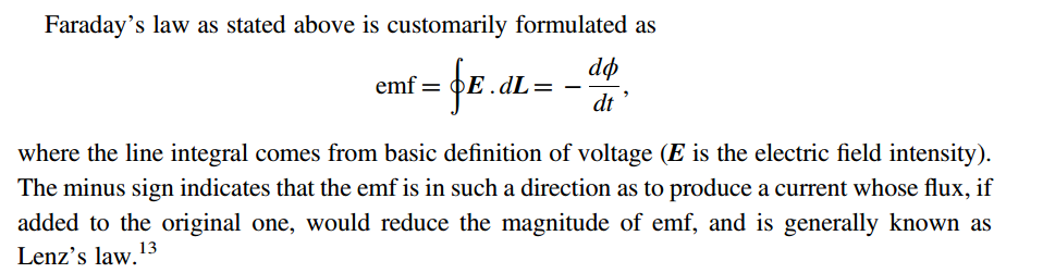
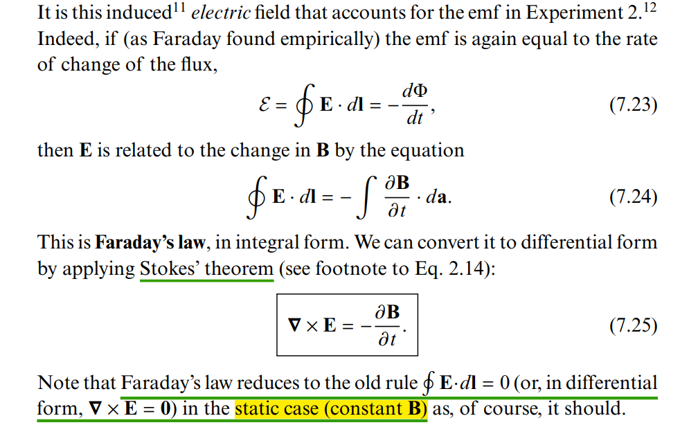
It also defines magnetic flux: \[ \boxed{\Phi_B=\int_S\mathbf B\cdot d\mathbf S} \] and appears in Faraday's law: \[ \oint_C\mathbf E\cdot d\mathbf l = -\frac{d}{dt} \int_S\mathbf B\cdot d\mathbf S. \] Gauss's law for magnetism is \[ \boxed{\nabla\cdot\mathbf B=0} \] or \[ \boxed{\oint_S\mathbf B\cdot d\mathbf S=0}. \] This is universally valid because magnetic monopoles have not been observed.
Electrodynamics
Faraday's Law
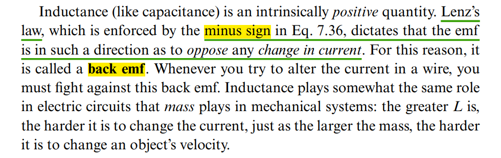
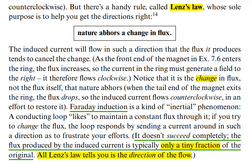
Lenz's law
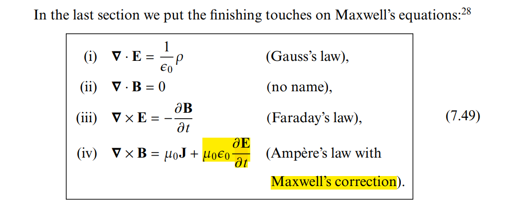
Ampère's law w/ Maxwell's correction
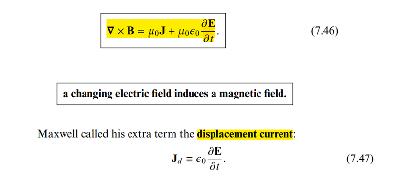
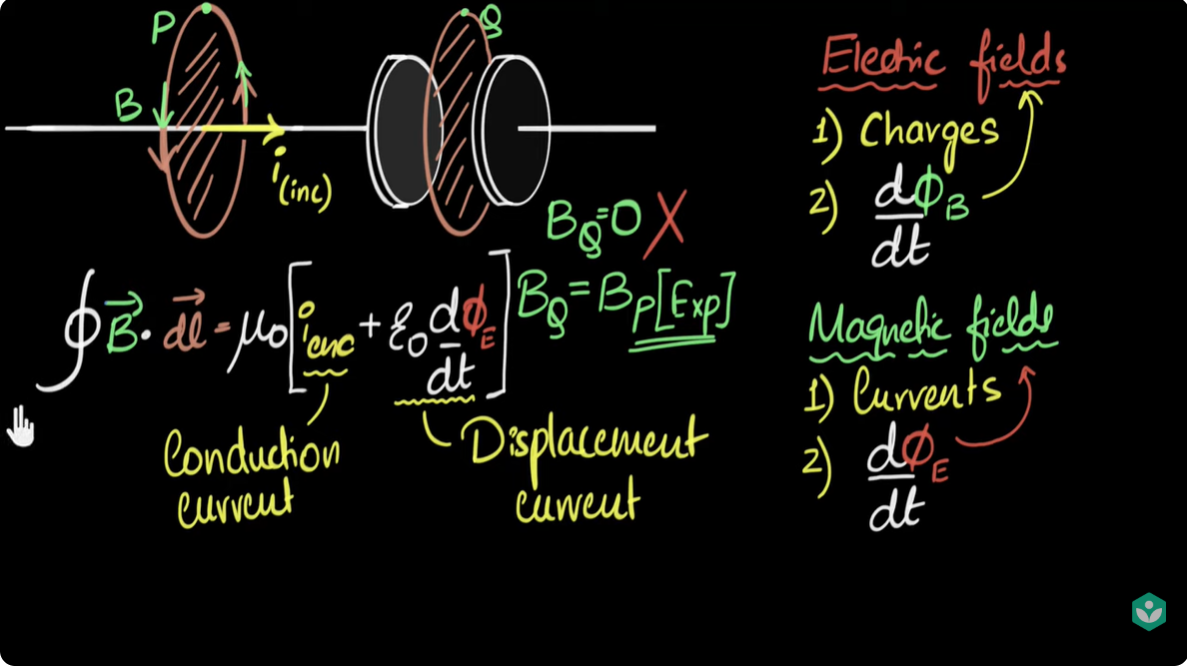

\[ \boxed{ \begin{aligned} \oint\mathbf H\cdot d\mathbf l &= I+\int\frac{\partial\mathbf D}{\partial t}\cdot d\mathbf S, \\[4pt] \nabla\times\mathbf B &= \mu_0\mathbf J+ \mu_0\varepsilon_0\frac{\partial\mathbf E}{\partial t} \end{aligned} } \] are equivalent in vacuum \[ \boxed{ \begin{aligned} \mathbf H,\mathbf D\text{ form} &\rightarrow \mathbf J_{\mathrm{free}},\\ \mathbf B,\mathbf E\text{ form} &\rightarrow \mathbf J_{\mathrm{total}}. \end{aligned} } \]
If \[ \mathbf B=\mu\mathbf H, \qquad \mathbf D=\varepsilon\mathbf E, \] with constant \(\mu\) and \(\varepsilon\), then \[ \boxed{ \oint_C\mathbf B\cdot d\mathbf l = \mu I_{\mathrm{free}} + \mu\varepsilon \int_S \frac{\partial\mathbf E}{\partial t}\cdot d\mathbf S } \]
Gauss’s law for magnetism
The universally valid equation is \[ \boxed{\oint_S \mathbf B\cdot d\mathbf S=0} \] or \[ \nabla\cdot\mathbf B=0. \] This expresses that magnetic field lines have no beginning or end—there are no observed magnetic monopoles
\[ \boxed{ \oint_S\mathbf B\cdot d\mathbf S=0 \text{ always, while } \oint_S\mathbf H\cdot d\mathbf S=0 \text{ only under additional conditions.} } \] i.e. \(\mathbf B=\mu\mathbf H\)
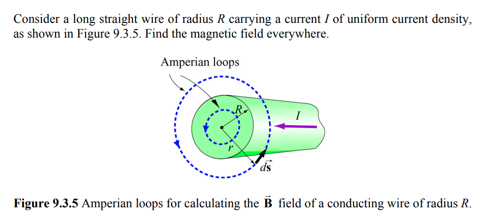
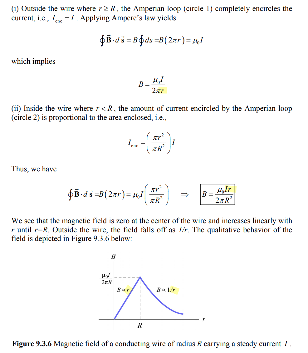
Field Inside and Outside a Current-Carrying Wire
Sources of Magnetic Fields [https://web.mit.edu/8.02t/www/802TEAL3D/visualizations/coursenotes/modules/guide09.pdf]
Displacement Current
A. Sheikholeslami, "Current Without Electrons [Circuit Intuitions]," in IEEE Solid-State Circuits Magazine, vol. 17, no. 4, pp. 8-10, Fall 2025
—, "Current Without Electric Field [Circuit Intuitions]," in IEEE Solid-State Circuits Magazine, vol. 18, no. 1, pp. 8-12, winter 2026
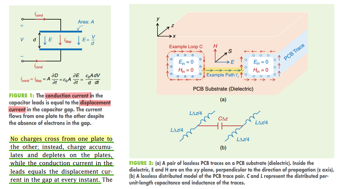
energy and information are carried by electric and magnetic fields (\(E\) and \(H\)) rather than by electron drift
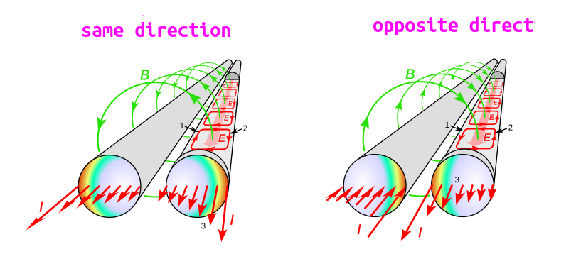
proximity effect & skin effect
- Skin effect concentrates current near the surface of a single conductor, while proximity effect concentrates current in specific regions of multiple conductors due to their interaction
- Skin effect is caused by the conductor's own magnetic field, while proximity effect is caused by the magnetic field of a nearby conductor
proximity effect is a redistribution of electric current occurring in nearby parallel electrical conductors carrying alternating current (AC), caused by magnetic effects (eddy currents)
skin effect is the tendency of AC current flow near the surface (or "skin") of a conductor, rather than throughout its cross-section, due to the magnetic field generated by the current itself
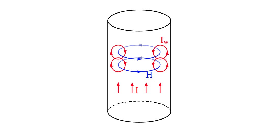
Cause of skin effect
A main current \(I\) flowing through a conductor induces a magnetic field \(H\). If the current increases, as in this figure, the resulting increase in \(H\) induces separate, circulating eddy currents \(I_W\) which partially cancel the current flow in the center and reinforce it near the skin
Eddy current
By Lenz's law, an eddy current creates a magnetic field that opposes the change in the magnetic field that created it, and thus eddy currents react back on the source of the magnetic field
reference
Griffiths, David J. Introduction to Electrodynamics. Fifth edition. Cambridge University Press, 2024. [pdf]
David Smith, Electromagnetic Theory for Complete Idiot, 2021
邓友金. 电磁学 2022春 [http://staff.ustc.edu.cn/~yjdeng/EM2022/EM2022.html]
谢处方、饶克谨、杨显清等.《电磁场与电磁波》(第五版),高等教育出. 版社,2019.
Scott Hughes. Spring 2005 8.022: Electricity & Magnetism [https://web.mit.edu/sahughes/www/8.022/]
Aditya Varma Muppala, EE 210 - Applied Electromagnetic Theory [https://adityamuppala.github.io/teaching210/]