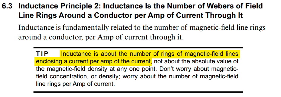
Loop and Partial Inductance
Basis of Inductance
Eric Bogatin. What Really Is Inductance? [https://speedingedge.com/wp-content/uploads/BTS006_What_Is_Inductance-2.pdf]
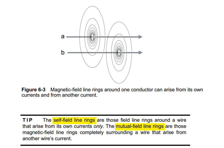
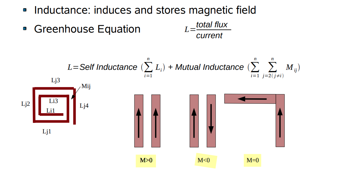
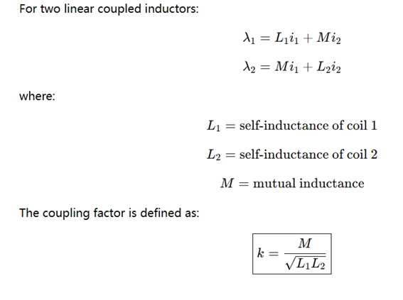
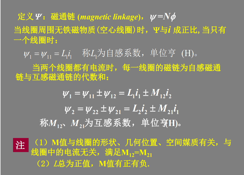
Self-Inductance & Mutual Inductance
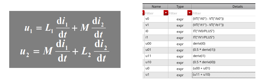
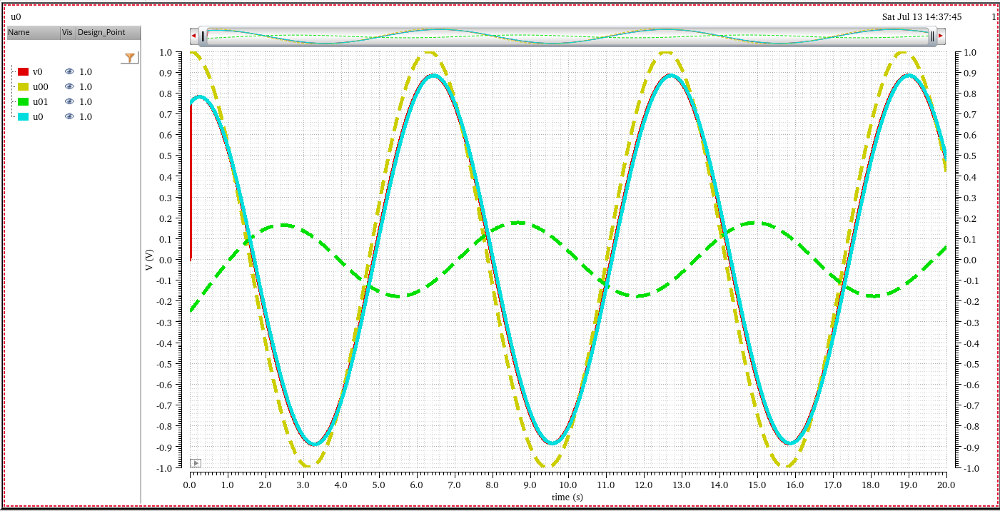
 \[\begin{align}
N_a &= L_a I_a + \color{red}M_{ab}I_b \\
N_b &= L_b I_b + \color{red}M_{ab}I_a
\end{align}\]
\[\begin{align}
N_a &= L_a I_a + \color{red}M_{ab}I_b \\
N_b &= L_b I_b + \color{red}M_{ab}I_a
\end{align}\]
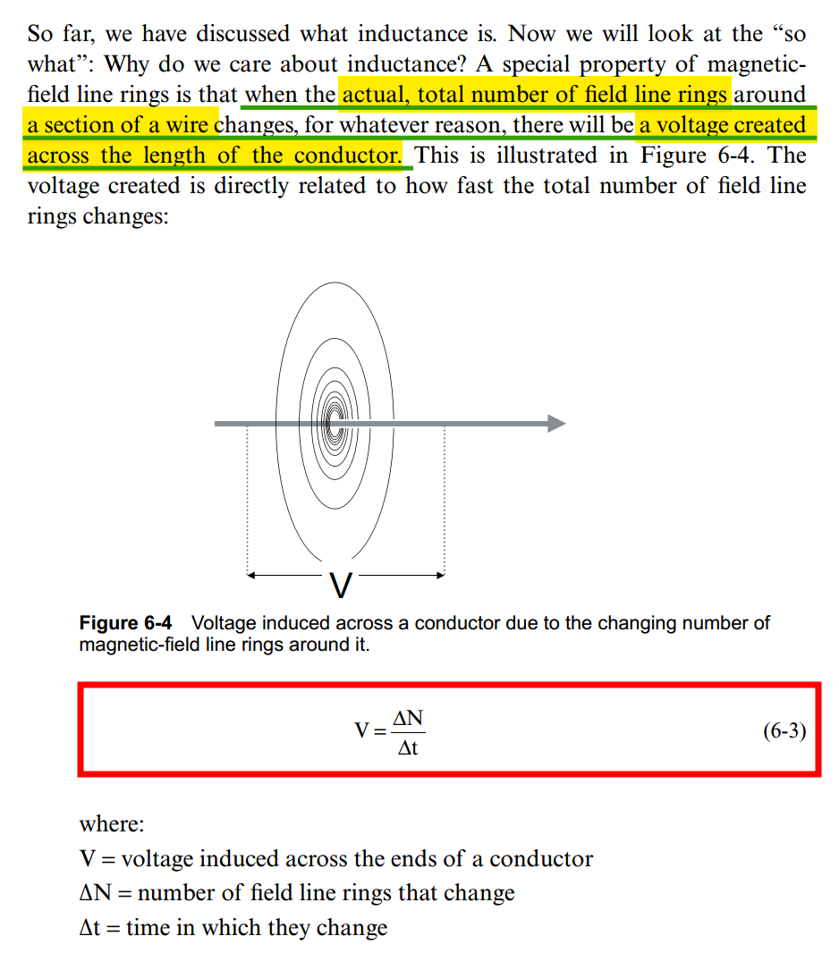
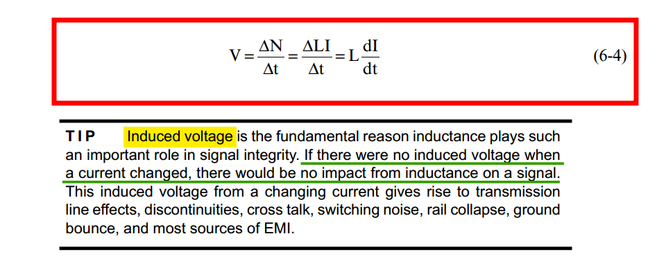
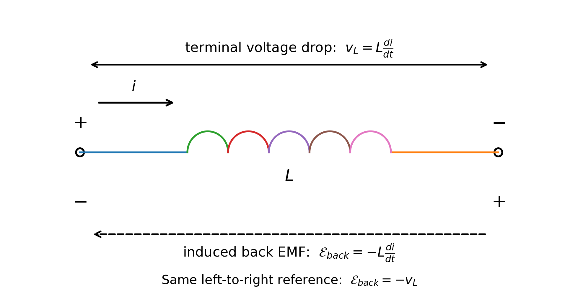
Induced voltage
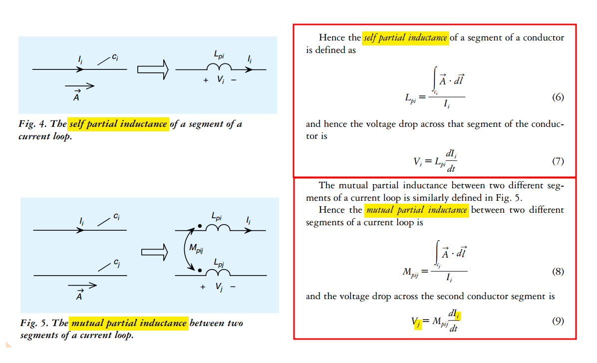
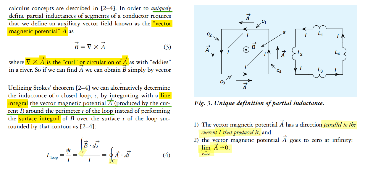
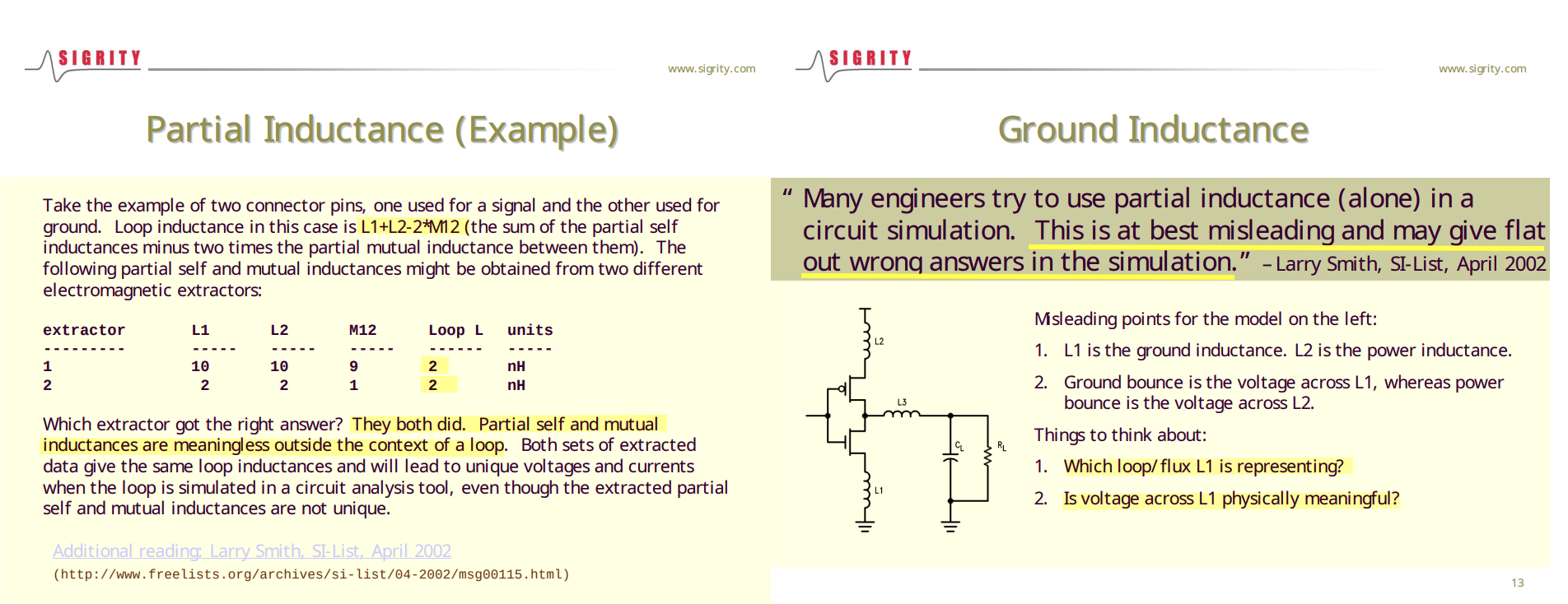
Partial Inductance
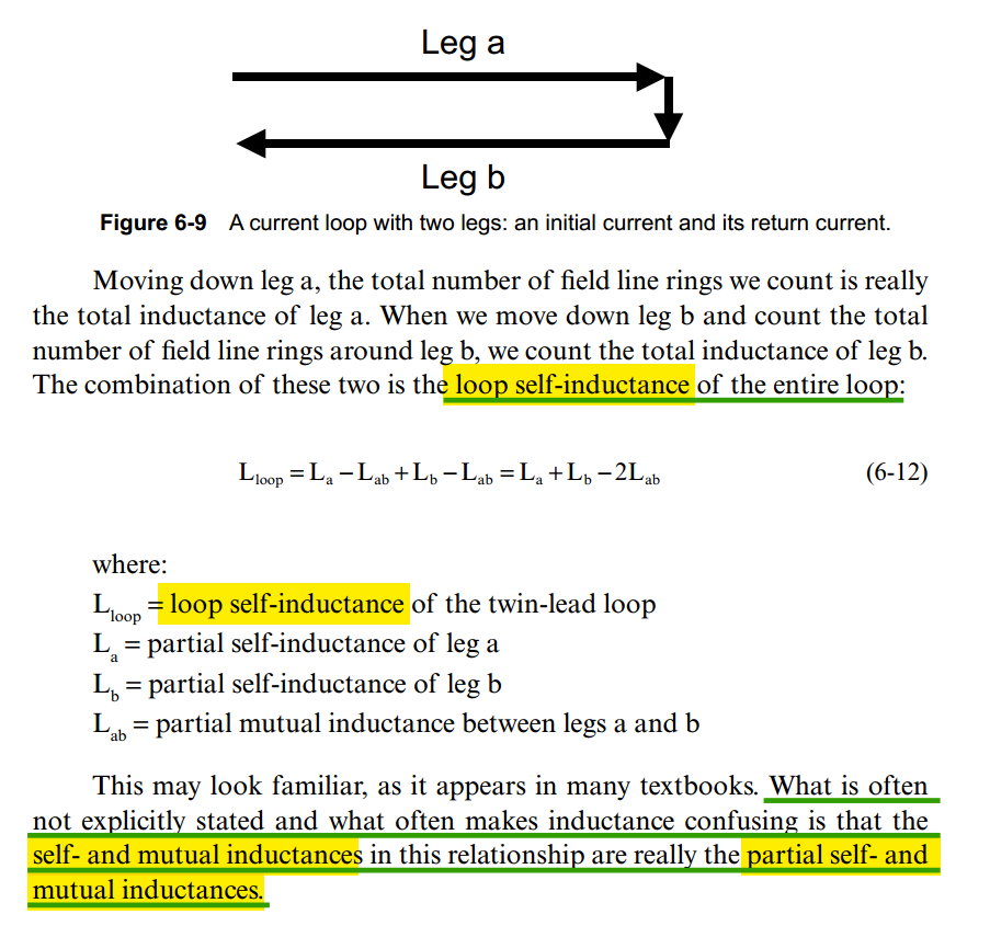
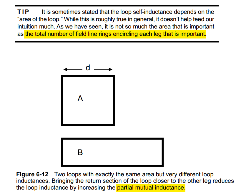
Loop Self & Mutual Inductance
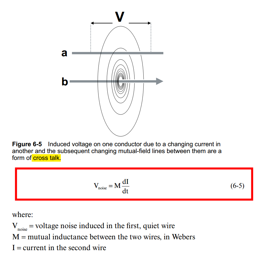
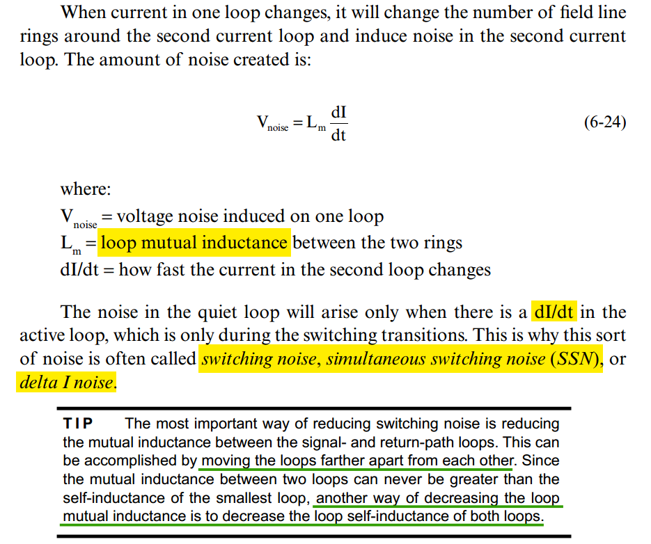
Loop Mutual Inductance
Equivalent Inductance of Multiple Inductors
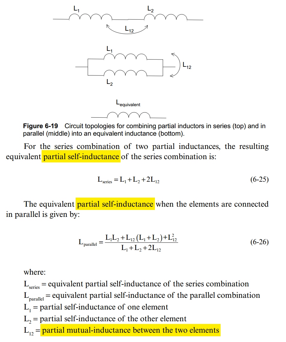 \[
L_\text{series} = L_1 + L_{12} + L_2 +L_{12} = L_1 + L_2 + 2L_{12}
\]
\[
L_\text{series} = L_1 + L_{12} + L_2 +L_{12} = L_1 + L_2 + 2L_{12}
\]
\[ L_\text{parallel} = (L_1 + L_{12})\parallel (L_2 + L_{12}) = \frac{L_1L_2 +L_{12}(L_1+L_2)+L_{12}^2}{L_1+L_2+2L_{12}} \]
internal self-inductance
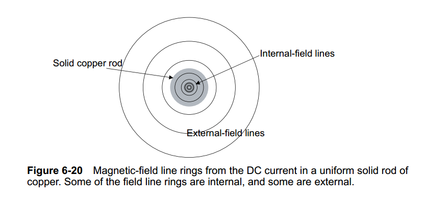
| self-inductance | magnetic-field line |
|---|---|
| internal self-inductance | inside the conductor |
| external self-inductance | outside the conductor |
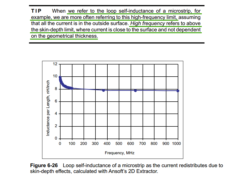
| Frequency | self-inductance |
|---|---|
| low frequency | \(L_\text{internal} + L_\text{external}\) |
| high frequency | \(L_\text{external}\) |
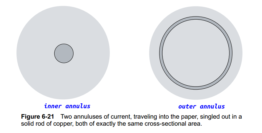
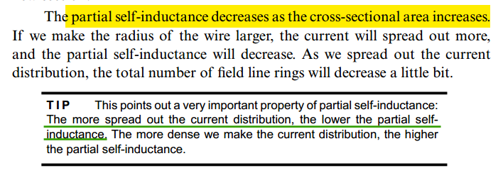
cross-sectional area
at low frequency
Partial Inductance
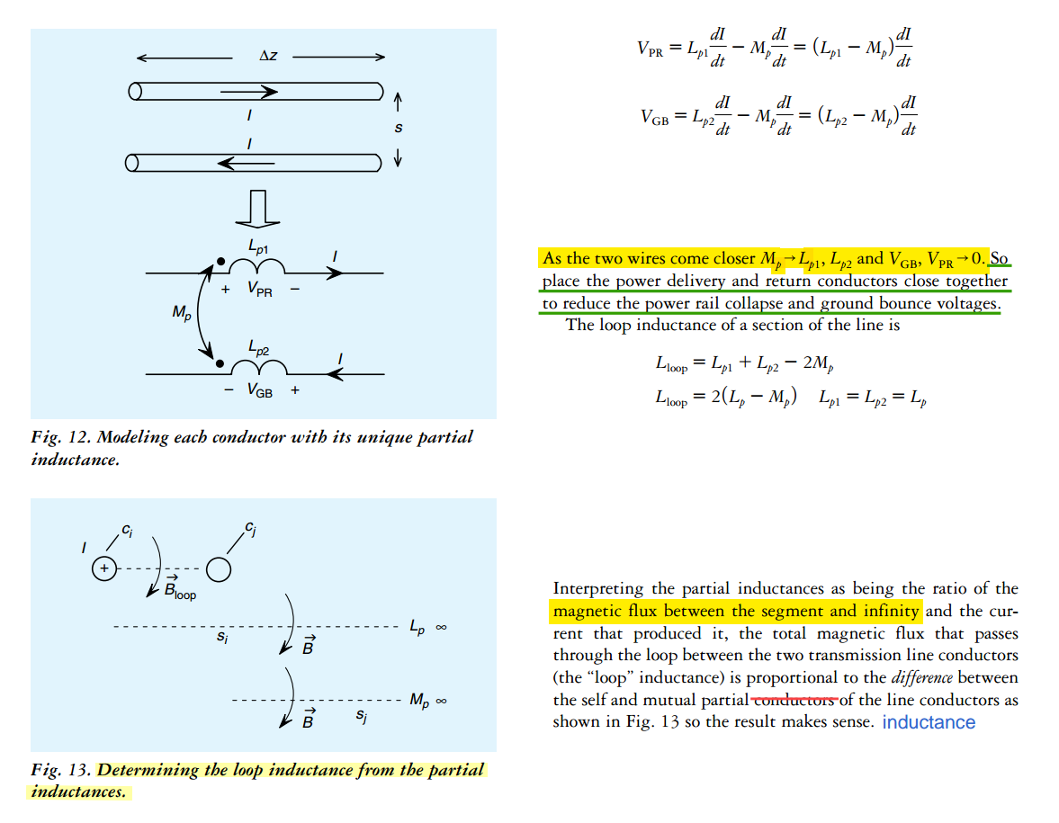
Loop Inductance is the sum of partial self-inductance and partial-mutual inductance
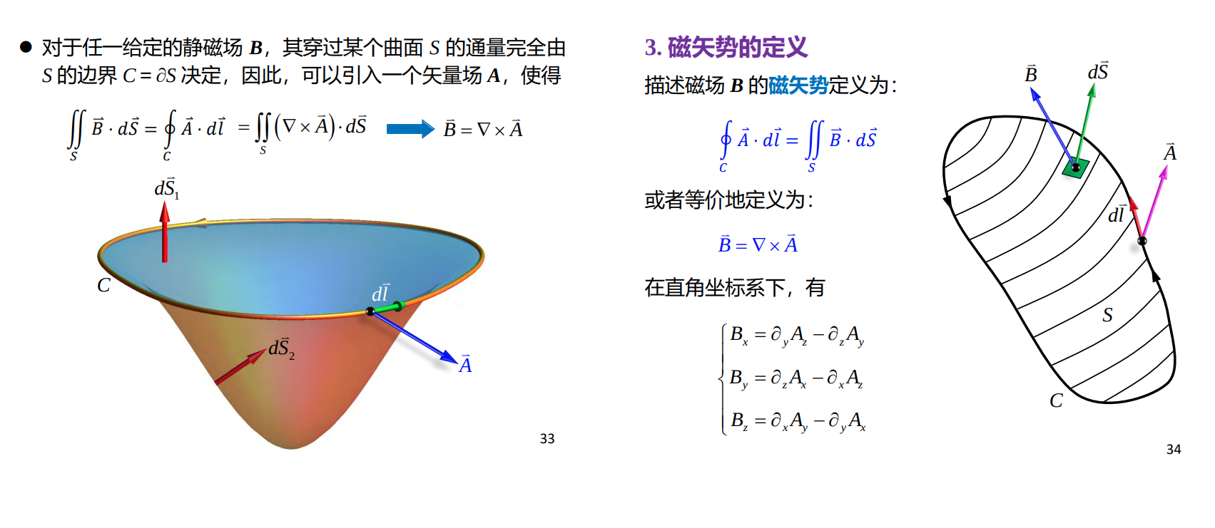
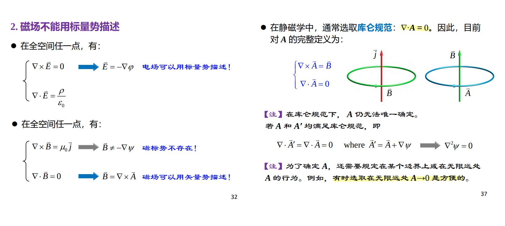
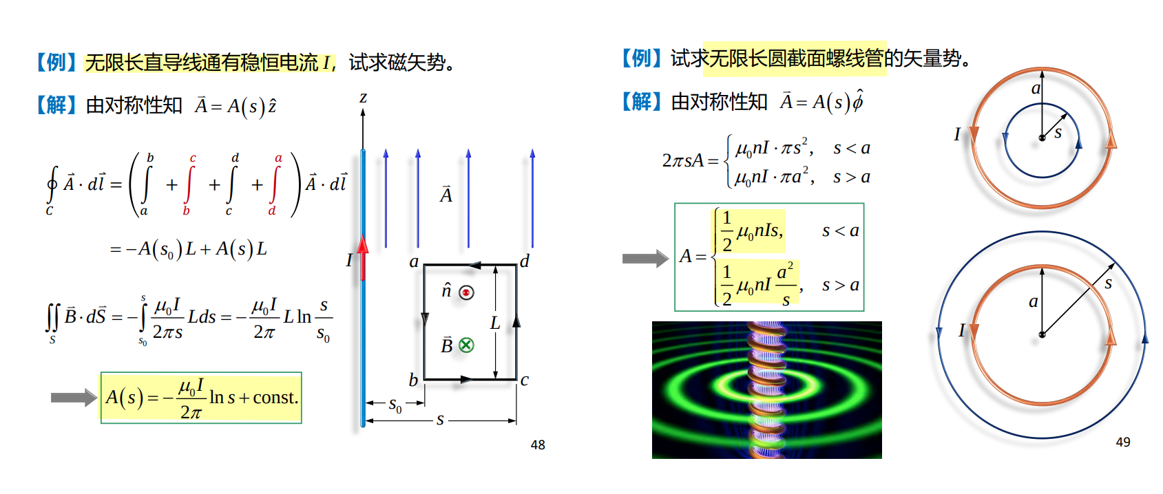
Magnetic Vector Potential (磁矢势)
Youjin Deng. 5-3 静磁场的基本规律 [http://staff.ustc.edu.cn/~yjdeng/EM2022/pdf/5-2(2022).pdf]
磁场不能用标量势描述
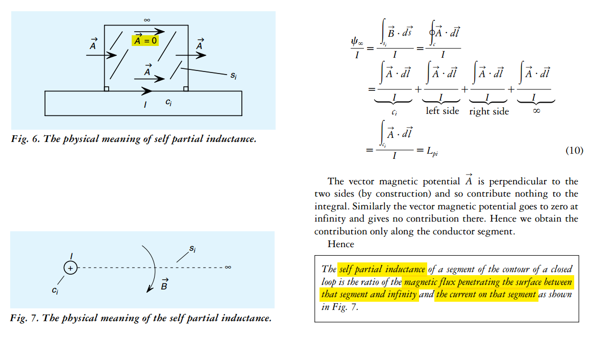
self partial inductance
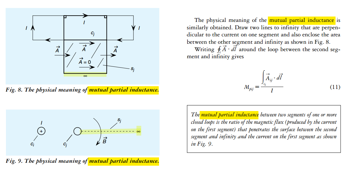
mutual partial inductance
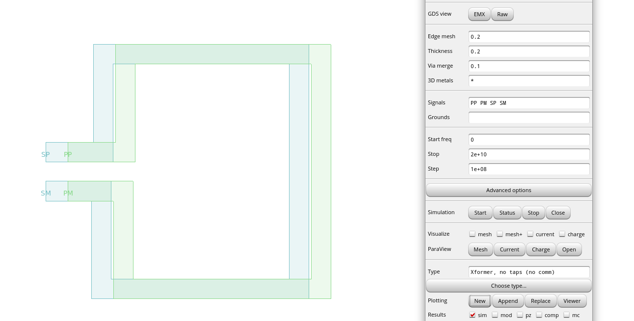
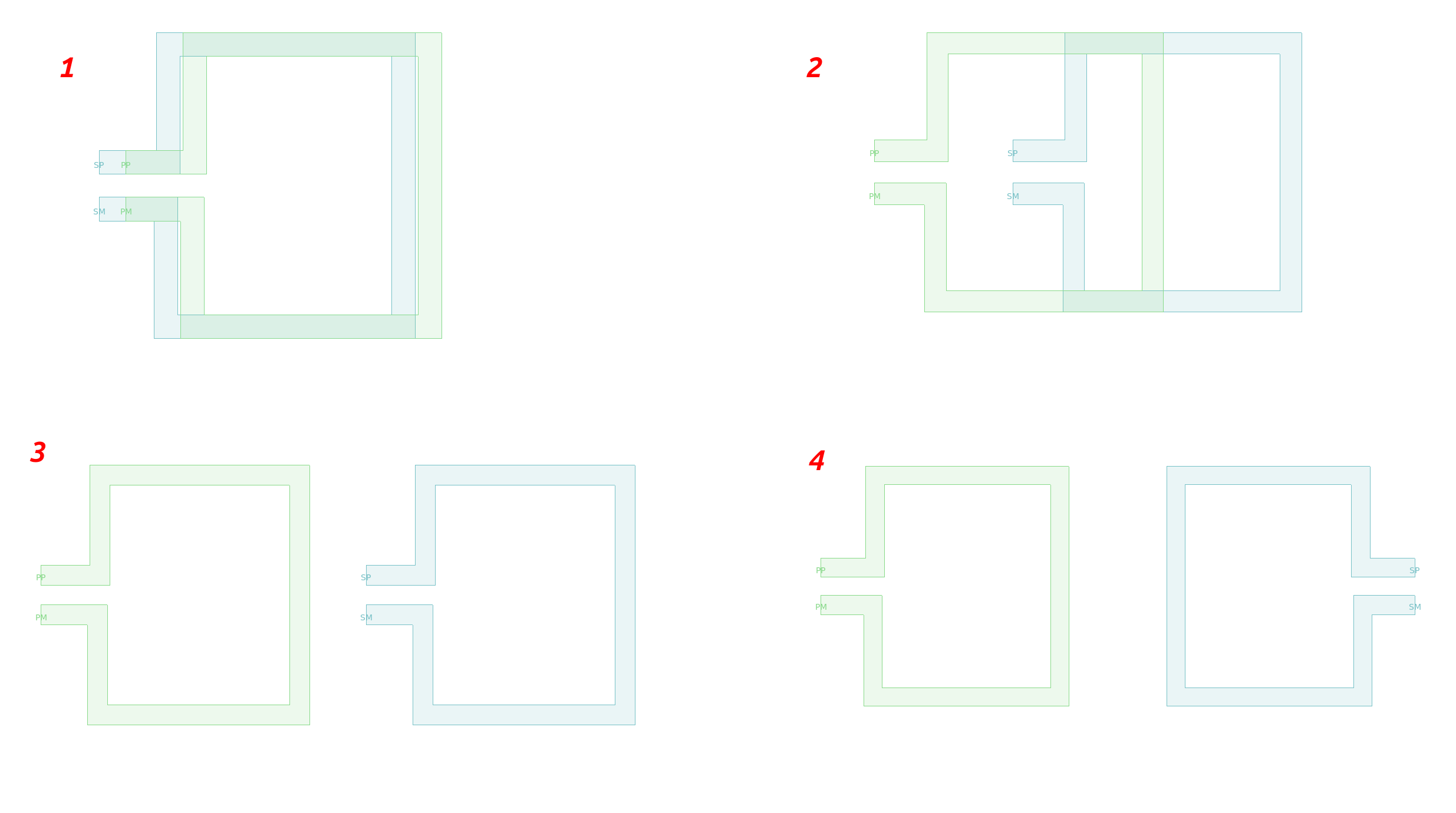
Ex. two-wire
[https://www.oldfriend.url.tw/Q3D/ansys_ch_Partial_Loop_Inductance.html]
Chapter 4.5. High Frequency Passive Devices [https://www.cambridge.org/il/files/7713/6698/2369/HFIC_chapter_4_passives.pdf]
On-Chip Spiral Inductors
Designer's Tips on RFIC Inductors [https://www.rfinsights.com/concepts/tips-on-rfic-inductors/]
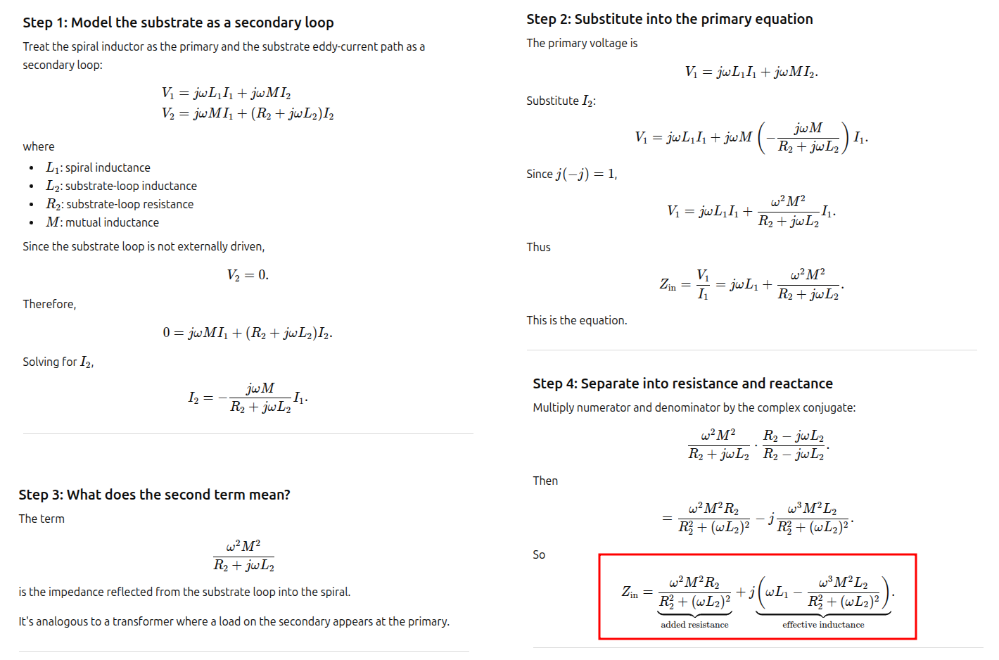
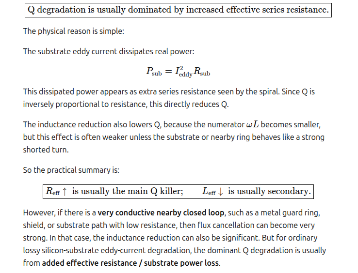
substrate-induced eddy-current loss
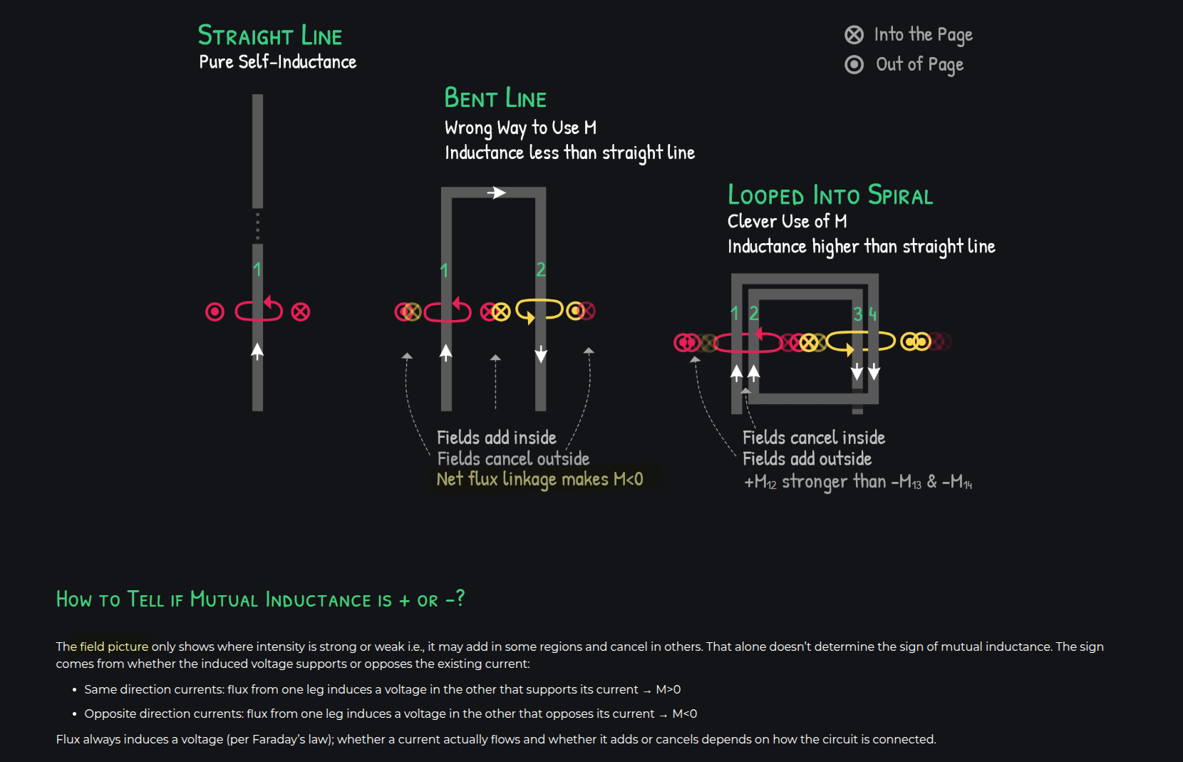
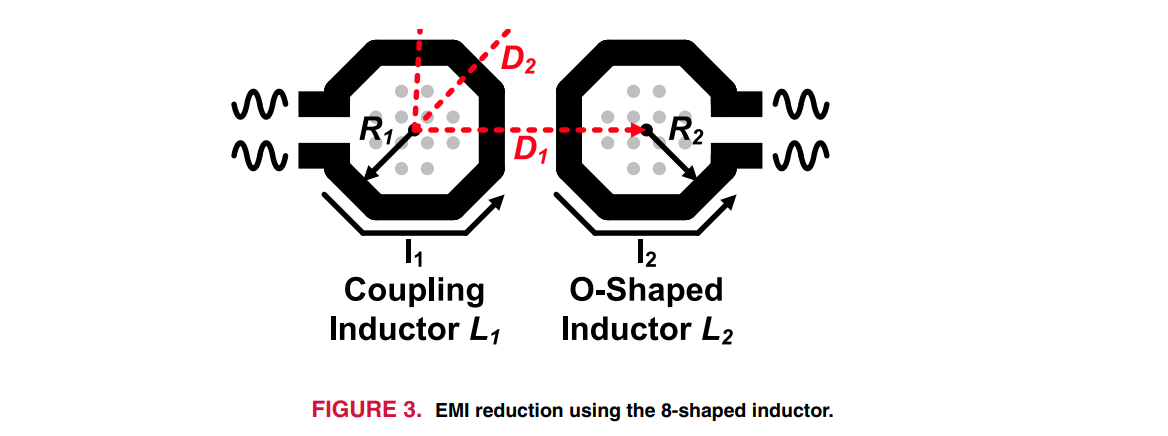
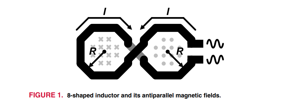
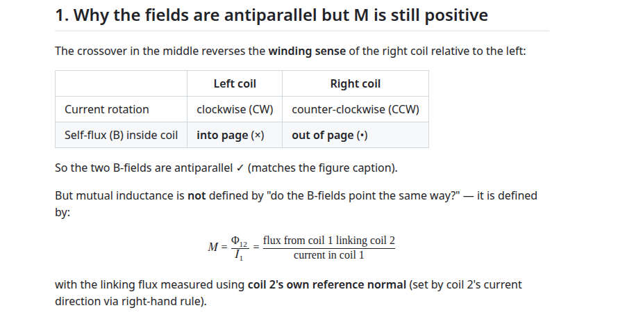
8-Shaped Inductor
J. H. Mikkelsen, O. K. Jensen and T. Larsen, "Crosstalk coupling effects of CMOS co-planar spiral inductors," Proceedings of the IEEE 2004 Custom Integrated Circuits Conference [https://sci-hub.jp/10.1109/CICC.2004.1358825]
P. Guan et al., "8-Shaped Inductors: An Essential Addition to RFIC Designers' Toolbox," in IEEE Open Journal of the Solid-State Circuits Society, vol. 4, pp. 131-146, 2024 [pdf]
- Field picture
- Partial-inductance picture
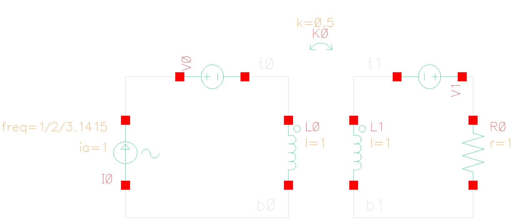
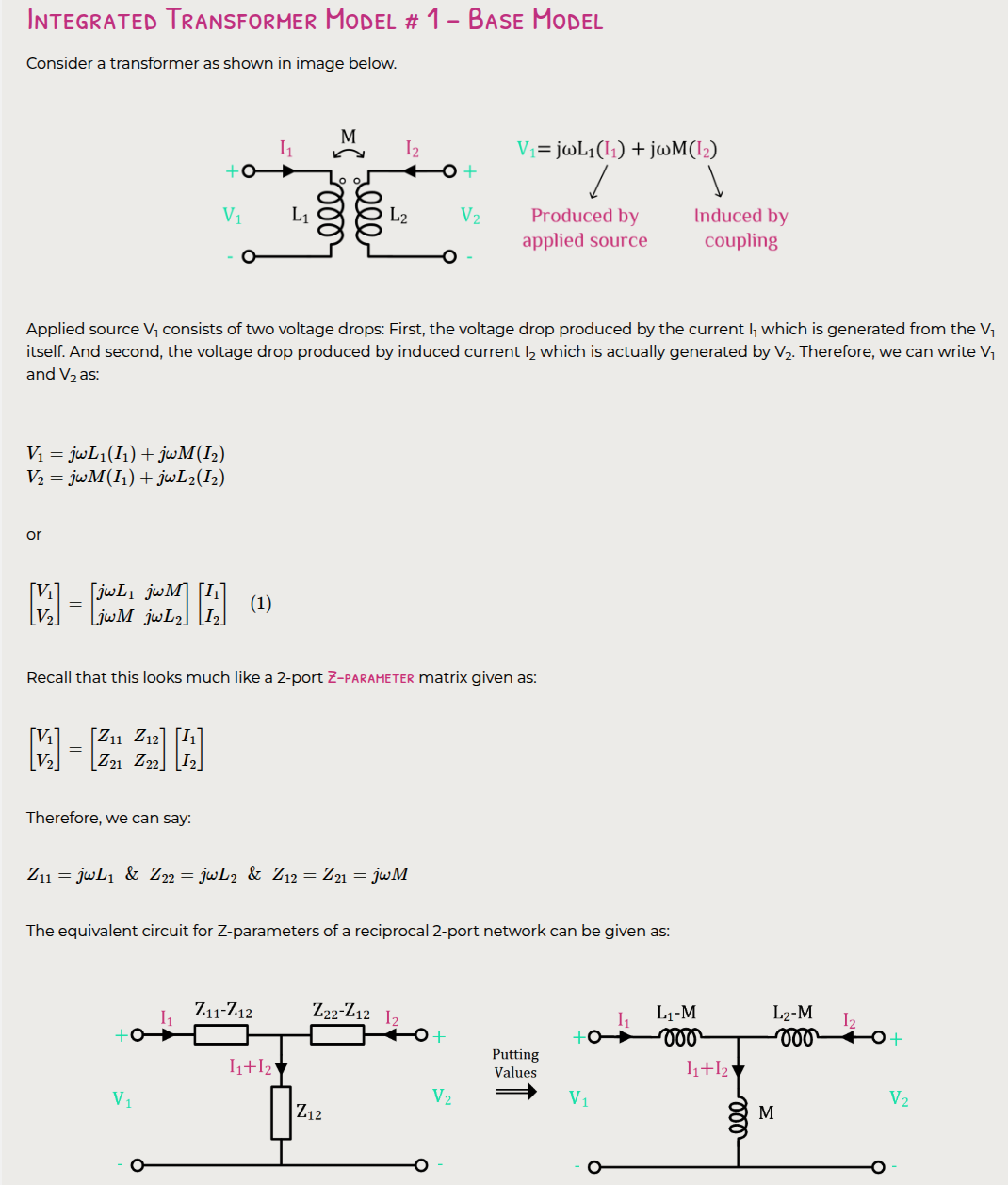
Transformer
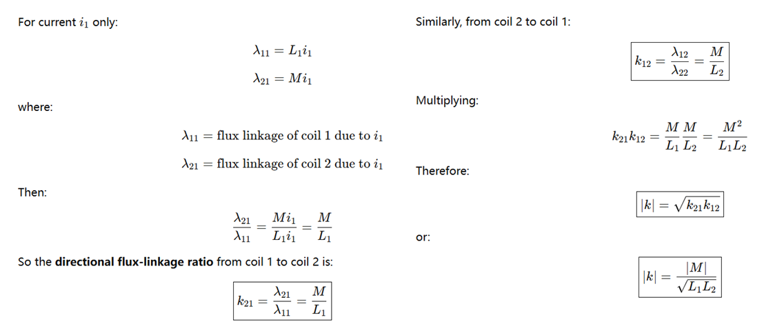
| Quantity | Symbol | Meaning | Formula |
|---|---|---|---|
| Magnetic flux | \(\Phi\) | Magnetic field \(\mathbf{B}\) passing through area \(\mathbf{S}\) | \(\Phi = \int_S \mathbf{B}\cdot d\mathbf{S}\) |
| Flux linkage | \(\lambda\) | Flux linked with coil turns \(N\) | \(\lambda = N\Phi\) |
| Induced EMF | \(\mathcal{E}\) | Voltage generated by changing flux linkage | \(\mathcal{E} = -\mathrm{d}\lambda/\mathrm{d}t\) |
| Self-inductance | \(L\) | Flux linkage caused by own current | \(L = \lambda/i\) |
| Mutual inductance | \(M\) | Flux linkage caused by another coil's current | \(M = \lambda_{21}/i_1\) |
| Coupling coefficient | \(k\) | Magnetic coupling strength between inductors | \(k = M/\sqrt{L_1L_2}\) |
ideal transformer
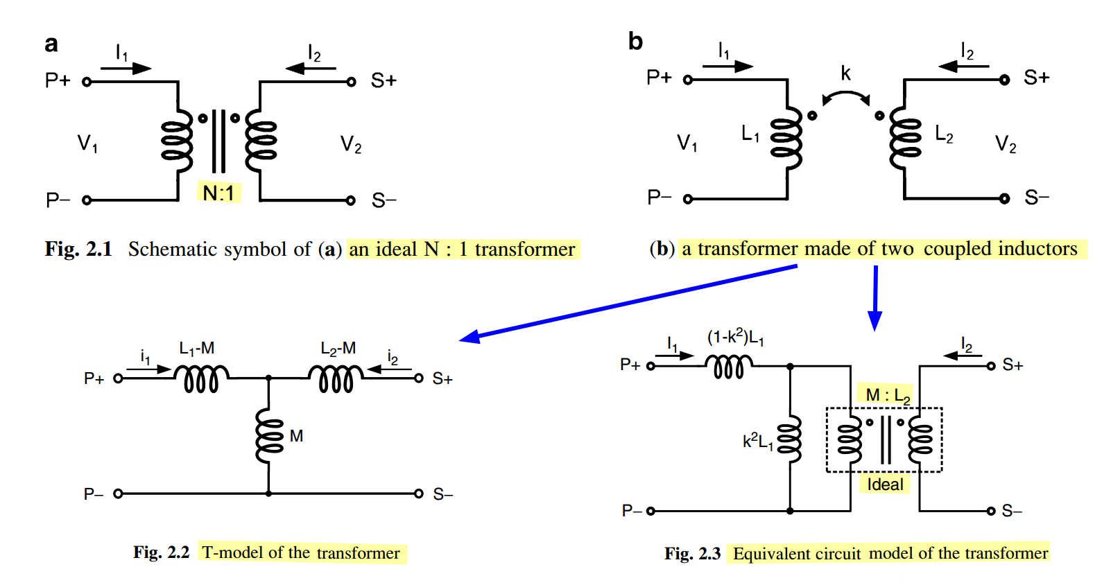
For an ideal N:1 transformer, \[ \boxed{V_1 = N V_2} \qquad \boxed{I_1 = -\frac{I_2}{N}} \] The minus sign comes from power conservation \[ V_1 I_1 + V_2 I_2 = 0 \] so \[ N V_2 I_1 + V_2 I_2 = 0 \] therefore \[ I_1 = -\frac{I_2}{N} \]
So Fig. 2.3 has exactly the same two-port equations as the original coupled inductors
Electromotive Force (EMF) \(\mathcal{E}\)
back emf
mutual inductance
\[ M_{12}=M_{21}=M \qquad \frac{N_1\Phi_{12}}{i_2}=\frac{N_2\Phi_{21}}{i_1} = M \]
Important: this does not mean \[ \Phi_{12} = \Phi_{21} \]
\(k\) vs. \(M\)
Coupling coefficient \(k\) is based on flux linkage ratios, not directly magnetic flux ratios

任何封闭电路中感应电动势大小,等于穿过这一电路磁通量的变化率。 \[ \epsilon = -\frac{\mathrm{d}\Phi_B}{\mathrm{d}t} \] 其中 \(\epsilon\)是电动势,单位为伏特
\(\Phi_B\)是通过电路的磁通量,单位为韦伯
电动势的方向(公式中的负号)由楞次定律决定
楞次定律: 由于磁通量的改变而产生的感应电流,其方向为抗拒磁通量改变的方向。
在回路中产生感应电动势的原因是由于通过回路平面的磁通量的变化,而不是磁通量本身,即使通过回路的磁通量很大,但只要它不随时间变化,回路中依然不会产生感应电动势。
自感电动势
当电流\(I\)随时间变化时,在线圈中产生的自感电动势为 \[ \epsilon = -L\frac{\mathrm{d}I}{\mathrm{d}t} \]
magnetic flux
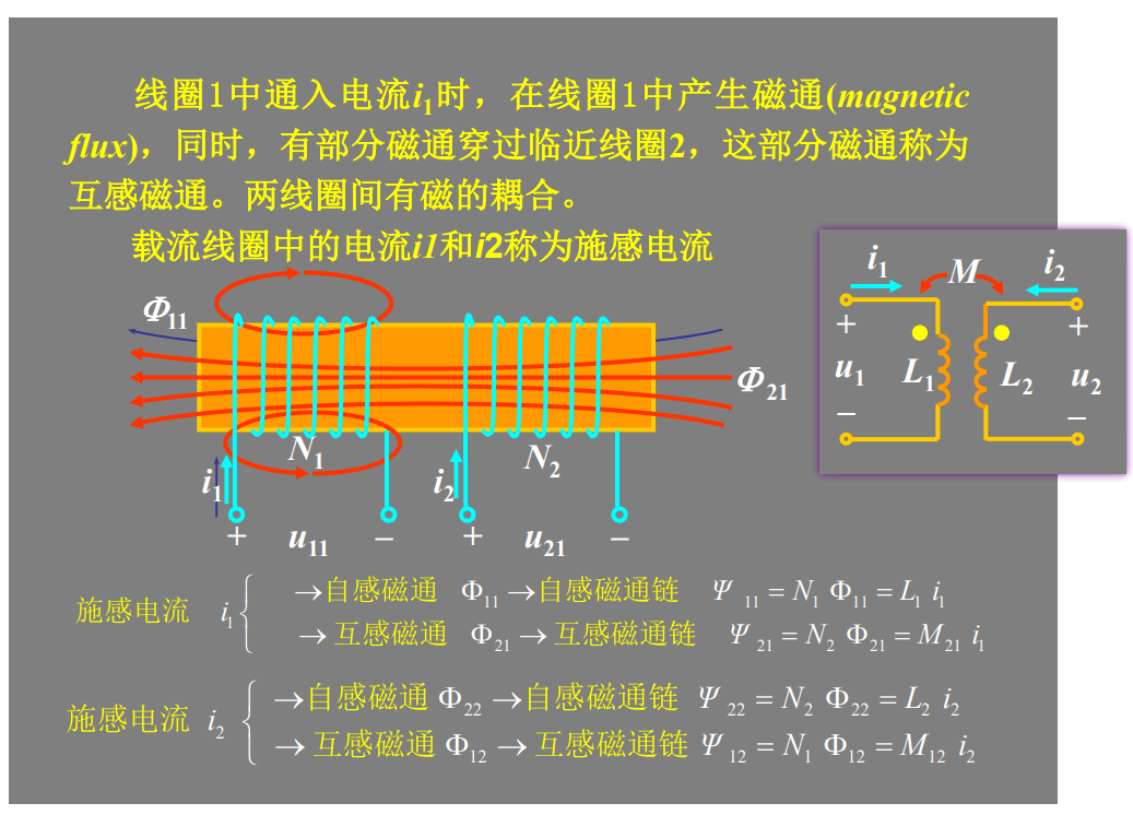
magnetic linkage
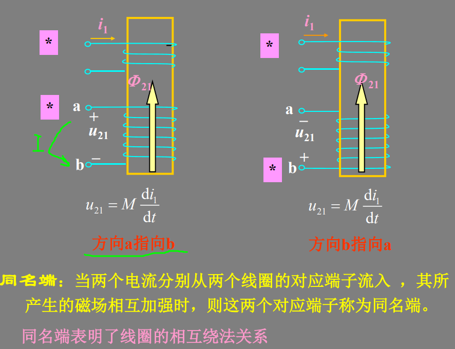
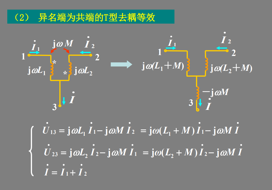
同名端:当两个电流分别从两个线圈的对应端子流入 ,其所 产生的磁场相互加强时,则这两个对应端子称为同名端。
Integrated Transformer Models [https://www.rfinsights.com/concepts/rfic-transformer-model/]
reference
Bogatin, E. (2018). Signal and power integrity, simplified. Prentice Hall. [pdf]
Paul, Clayton R. Inductance: Loop and Partial. Hoboken, N.J. : [Piscataway, N.J.]: Wiley ; IEEE, 2010. [pdf]
Spartaco Caniggia. Signal Integrity and Radiated Emission of High‐Speed Digital Systems. Wiley 2008
Luong, H. C., & Yin, J. (2016). Transformer-based design techniques for oscillators and frequency dividers. Springer International Publishing
ISSCC2002. Special Topic Evening Discussion Sessions SE1: Inductance: Implications and Solutions for High-Speed Digital Circuits [vSE1_Blaauw], [vSE1_Gauthier], [vSE1_Morton, [vSE1_Restle]]
Y. Massoud and Y. Ismail, "Gasping the impact of on-chip inductance," in IEEE Circuits and Devices Magazine, vol. 17, no. 4, pp. 14-21, July 2001 [https://sci-hub.se/10.1109/101.950046]
Clayton R. Paul, Partial Inductance [https://ewh.ieee.org/soc/emcs/acstrial/newsletters/summer10/PP_PartialInductance.pdf]
Cheung-Wei Lam. Common Misconceptions about Inductance & Current Return Path [https://ewh.ieee.org/r6/scv/emc/archive/022010Lam.pdf]
Randy Wolff. Signal Loop Inductance in [Pin] and [Package Model] [https://ibis.org/summits/feb10/wolff.pdf]
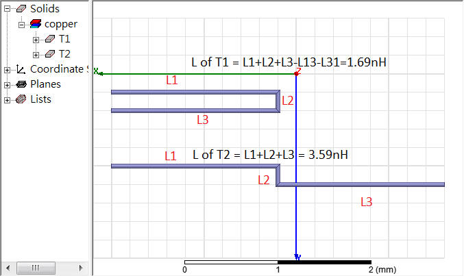
ANSYS Q3D Getting Started LE05. Module 5: Q3D Inductance Matrix Reduction [https://innovationspace.ansys.com/courses/wp-content/uploads/sites/5/2021/07/Q3D_GS_2020R1_EN_LE05_Ind_Matrix.pdf]