Resonant Circuits
A resonant circuit refers to an electrical circuit using circuit elements such as an inductor (L) and a capacitor (C) to cause resonance at a specific frequency.
There are two types of resonant circuits:
- series resonant circuits
- parallel resonant circuits
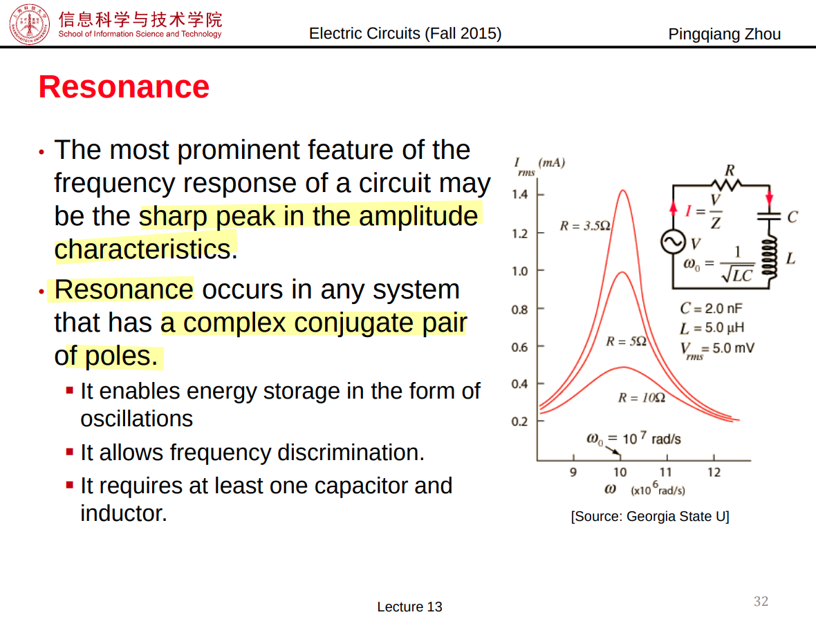
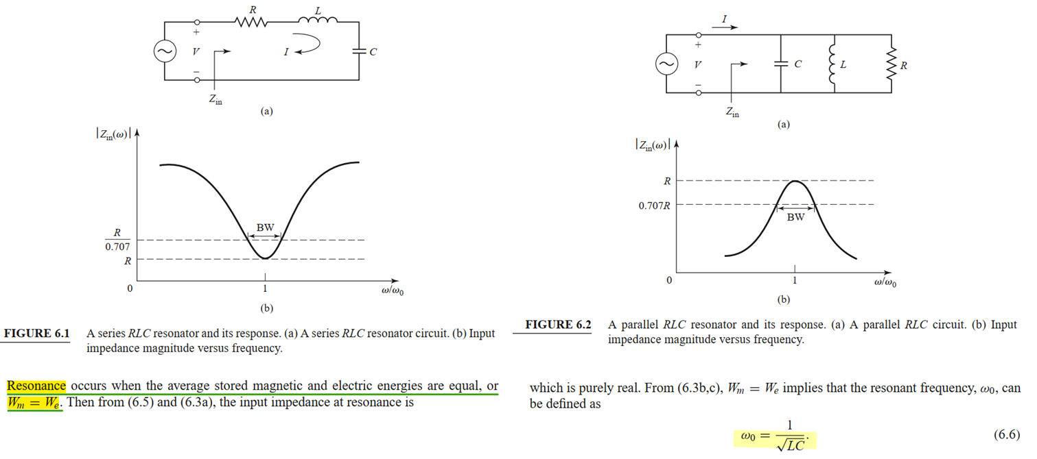
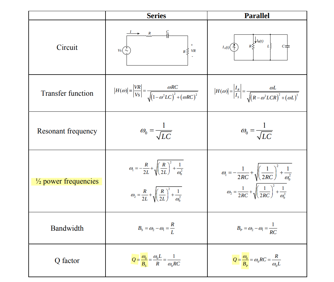
In a series resonant circuit, the impedance of the circuit reaches its minimum value at resonance, whereas in a parallel resonant circuit, the impedance reaches its maximum value
antiresonance

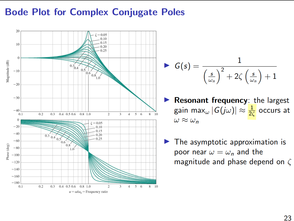
Resonant Frequency
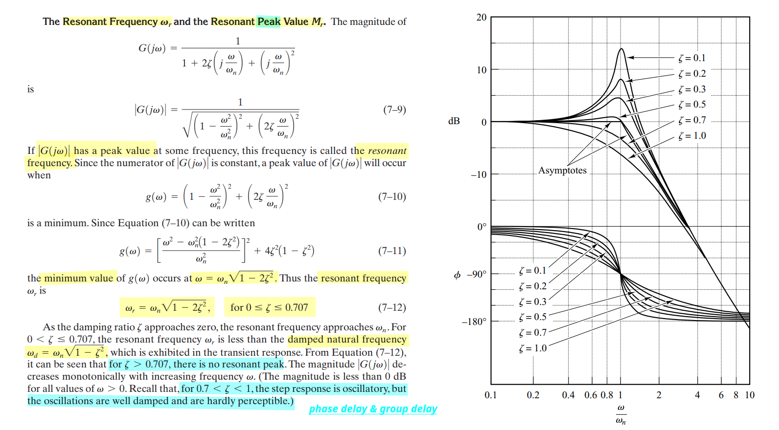
\(\zeta \lt 1\): Complex-Conjugate Poles, but not resonant peak
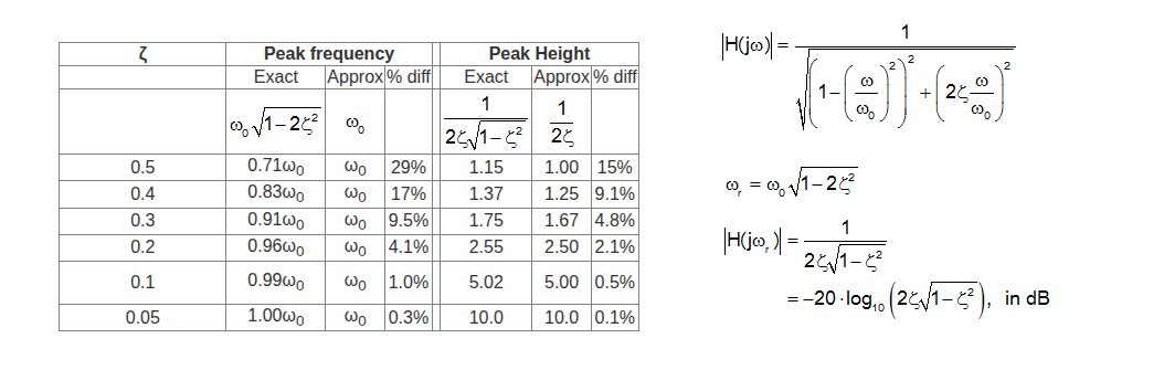
\(\zeta \lt \sqrt{2}/2\): resonant peak
[https://lpsa.swarthmore.edu/Bode/underdamped/underdampedApprox.html]
Prof. M. Green / U.C. Irvine EECS 270C / Winter 2016 Week5 [pdf]
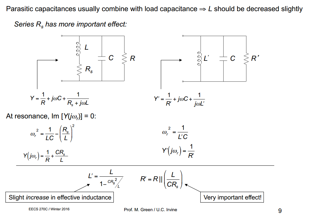
with \(L' = \frac{L}{1 - CR_s^2/L}\)
resonant frequency in right equivalent circuit \[ \omega_r^2 = \frac{1}{L'C} = \frac{1}{LC} - \left(\frac{R_s}{L}\right)^2 \] which shows that the equivalent circuit preserves the resonant frequency of the original network.
LC Resonator

Complex Conjugate Zeros
Complex Conjugate Poles
\(\zeta \to 0\) push \(|G(s)\approx \frac{1}{2\zeta} \to+\infty\)
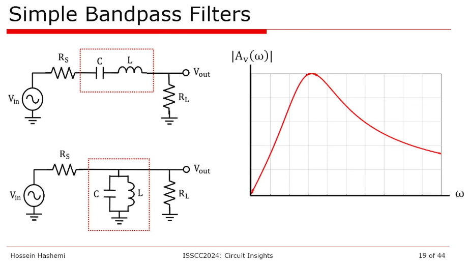
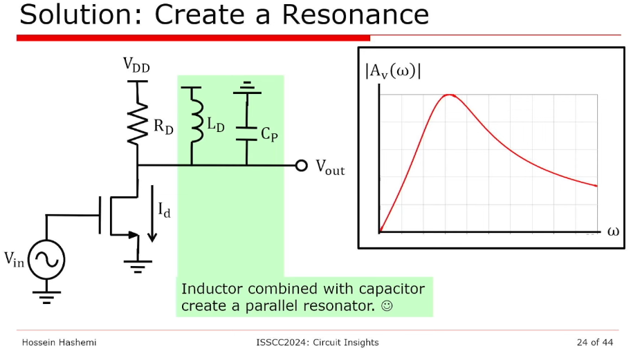
Frequency selectivity
EEE 211 ANALOG ELECTRONICS [https://www.ee.bilkent.edu.tr/~eee211/LectureNotes/Chapter%20-%2004.pdf]
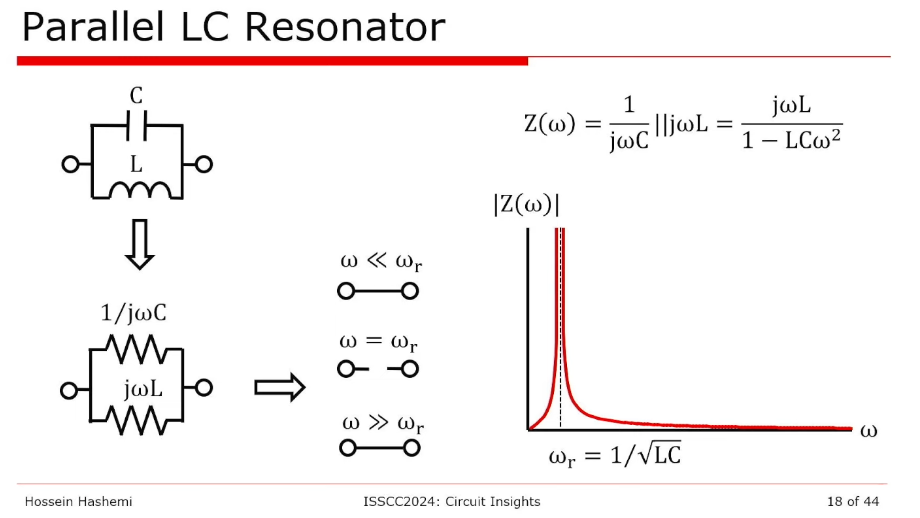
Parallel resonance
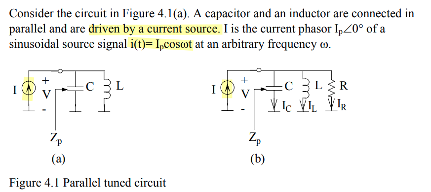
assuming \(i(t) = I_p\cos\omega_0 t\), where \(\omega_0 =1/\sqrt{LC}\) , suppose all current flow into \(R\) \[ V(t) = I_pR\cdot \cos\omega_0 t \] \(I_C\), the current flow through \(C\) \[ \color{red}I_C(t)=C\frac{\mathrm{d}V(t)}{\mathrm{d}t}=-C\omega_0\cdot I_pR\cdot \sin\omega_0 t \] Then, we have voltage between \(L\), given \(I_L = -I_C\) \[ V_L(t) = L\frac{\mathrm{d}I_L(t)}{\mathrm{d}t} = LC\omega_0^2\cdot I_pR\cdot \cos\omega_0 t = I_pR\cdot \cos\omega_0 t \]
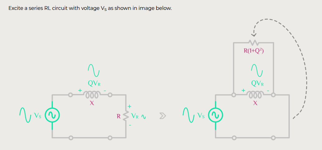
Series resonance
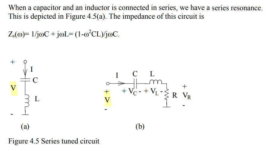
assuming \(V(t)=V_s\cos\omega_0t\),
where \(\omega_0 =1/\sqrt{LC}\) ,
suppose all current flow into \(V_C+V_L=0\) \[
V_R(t) = V(t) = V_s\cos\omega_0t
\] then \[
I_s(t) = \frac{V_s}{R}\cos\omega_0 t
\] \(V_L(t)\) is obtained \[
V_L(t) = L\frac{\mathrm{d}I_s(t)}{\mathrm{d}t} = -L\omega_0\cdot
\frac{V_s}{R}\sin\omega_0 t
\] Then \[
V_C(t) = V(t) - (V_L(t) + V_R(t)) = -V_L(t)
\] Therefore, \(I_C\) current
flow through \(C\) \[
I_C(t) = C\frac{\mathrm{d}V_C(t)}{\mathrm{d}t}= LC\omega_0^2\cdot
\frac{V_s}{R}\cos\omega_0 t= \frac{V_s}{R}\cos\omega_0 t
\] voltage potential between \(L\) and \(C\) \[
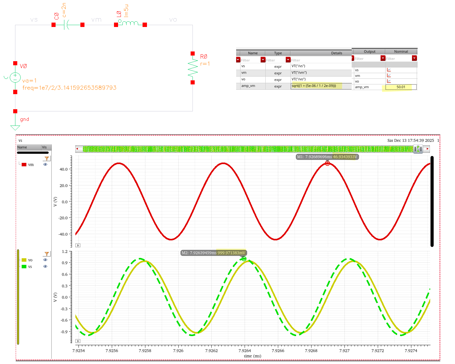
\color{red}V_m(t) = V_R(t) + V_L(t) = V_s\cos\omega_0t -L\omega_0\cdot
\frac{V_s}{R}\sin\omega_0 t = V_s\sqrt{1+L/R^2C}\cos(\omega_0t+\phi)
\] 
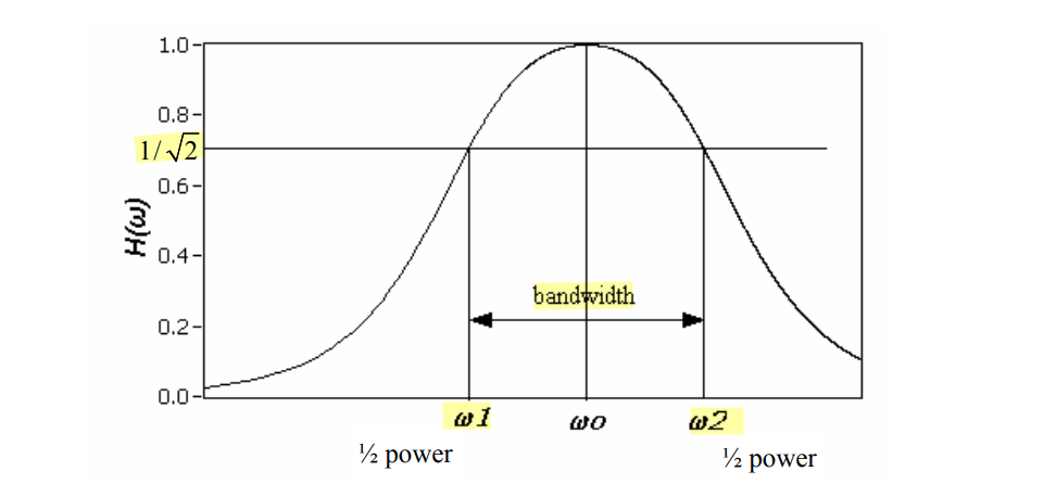
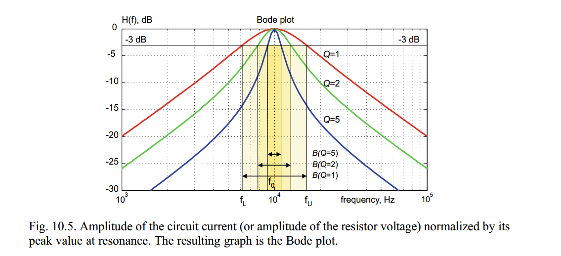
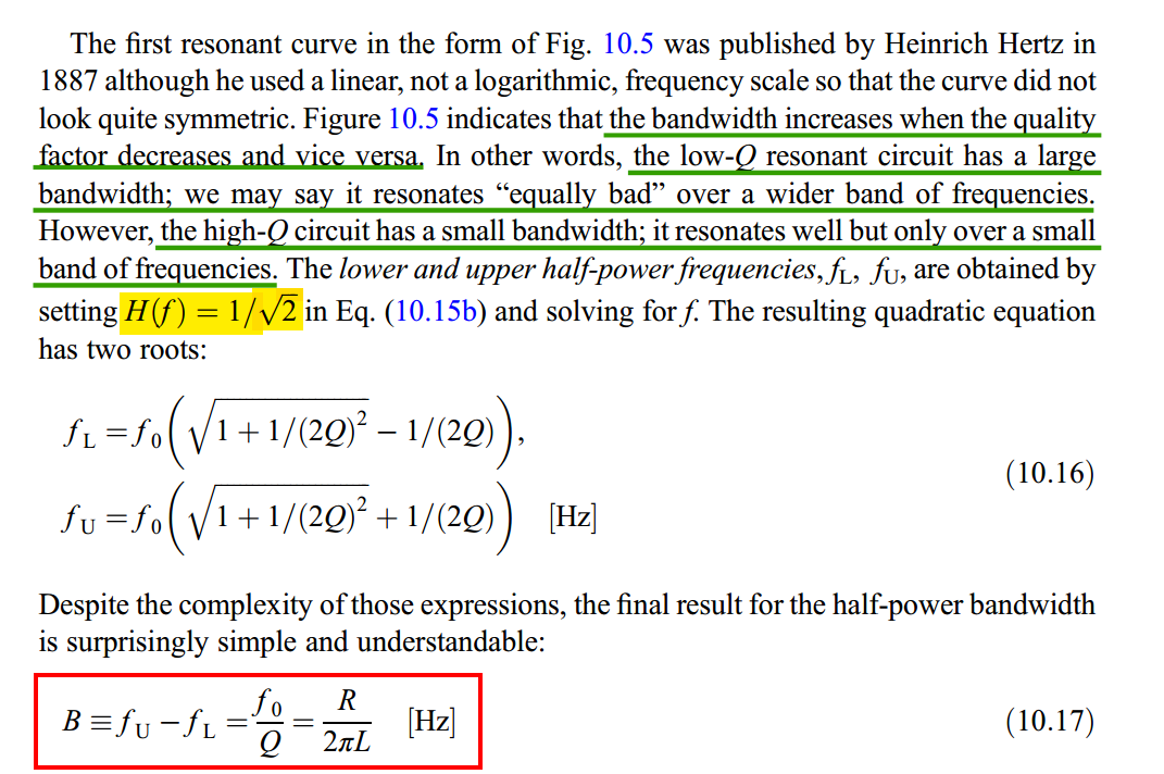
Bandwidth
Frequency response: Resonance, Bandwidth, Q factor [https://ocw.mit.edu/courses/6-071j-introduction-to-electronics-signals-and-measurement-spring-2006/5bcec4bfba5f2e99754b77509e9e7ab4_resonance_qfactr.pdf]
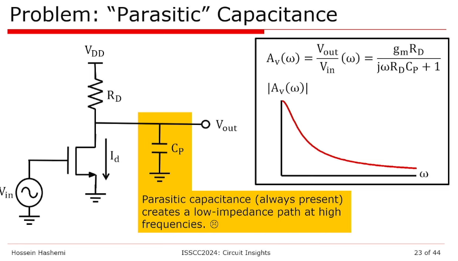
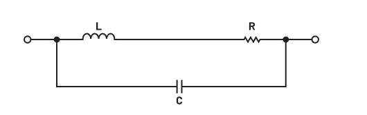
Non ideal capacitor & inductor
Tank Circuits/Impedances [https://stanford.edu/class/ee133/handouts/lecturenotes/lecture5_tank.pdf]
Resonant Circuits [https://web.ece.ucsb.edu/~long/ece145b/Resonators.pdf]
Series & Parallel Impedance Parameters and Equivalent Circuits [https://assets.testequity.com/te1/Documents/pdf/series-parallel-impedance-parameters-an.pdf]
ES Lecture 35: Non ideal capacitor, Capacitor Q and series RC to parallel RC conversion [https://youtu.be/CJ_2U5pEB4o]
Non ideal Capacitor
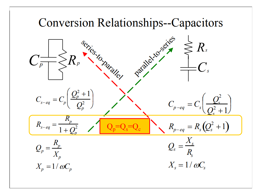

\[ Q_s = \frac{X_s}{R_s} = X_p\frac{Q_p^2}{Q_p^2+1}\cdot \frac{Q_p^2+1}{R_p} =\frac{Q_p^2}{R_p/X_p}=Q_p \]
So long as \(Q_s\gg 1\) \[ \boxed{R_p \approx Q_s^2R_s \qquad C_p \approx C_s} \]

Non ideal Inductor
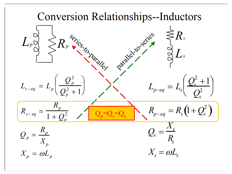
So long as \(Q_s\gg 1\) \[ \boxed{R_p \approx Q_s^2R_s \qquad L_p \approx L_s} \]
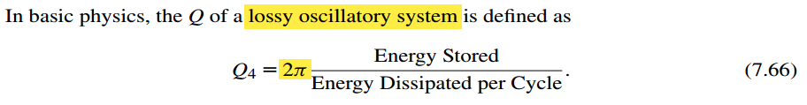
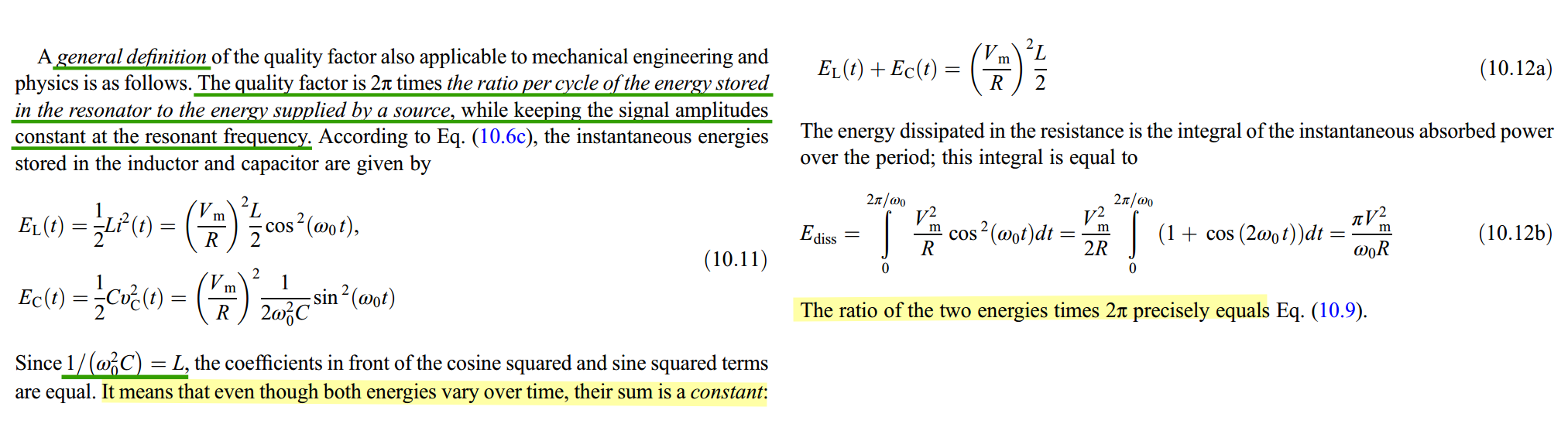
Q by general definition
RFInsights, Series to Parallel Conversion using Quality Factor [https://www.rfinsights.com/concepts/series-to-parallel/]
Parallel C, R: \[ Q=2\pi\cdot \frac{\frac{1}{2}CV_0^2}{\frac{V_0^2}{2R}\cdot \frac{2\pi}{\omega}}=R\cdot \omega C \]
Series C, R: \[ Q = 2\pi \cdot \left. \frac{\frac{1}{2}CV_0^2}{\frac{I_0^2}{2}R\cdot \frac{2\pi}{\omega}} \right|_{I_0=\omega CV_0} = \frac{1}{R\cdot\omega C} \]
Series L, R: \[ Q=2\pi\cdot \frac{\frac{1}{2}LI_0^2}{\frac{I_0^2}{2}R\cdot \frac{2\pi}{\omega}}=\frac{\omega L}{R} \]
Parallel L, R: \[ Q = 2\pi \cdot \left. \frac{\frac{1}{2}LI_0^2}{\frac{V_0^2}{2R}R\cdot \frac{2\pi}{\omega}} \right|_{V_0=\omega LI_0} = \frac{R}{\omega L} \]
Series/Parallel RLC tank
Makarov, Sergey & Ludwig, Reinhold & Bitar, Joyce. (2016). Practical Electrical Engineering. 10.1007/978-3-319-21173-2. [pdf]
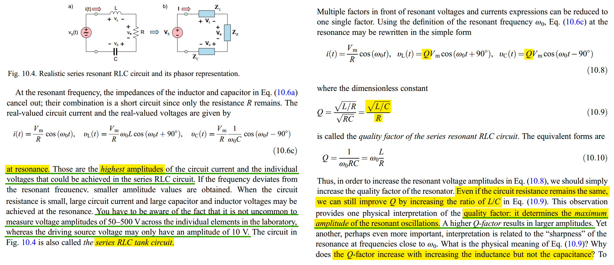
Series Resonant RLC
The series RLC resonator is a voltage divider, driven by an alternating voltage source \(v_s(t)=V_m\cos\omega t\)
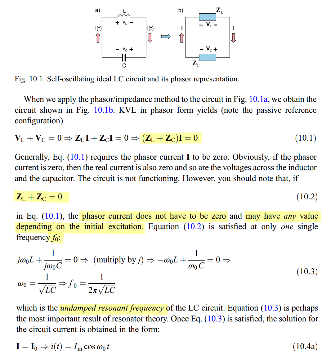
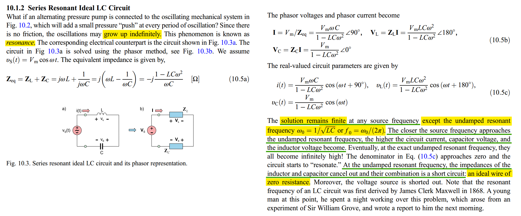
The ideal LC circuit never exists in practice
Resonance Condition & Quality Factor Q
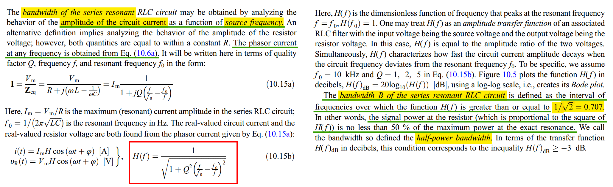
bandwidth \(B\) of the series resonant RLC circuit — half-power bandwidth.
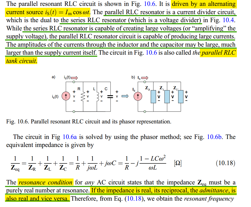
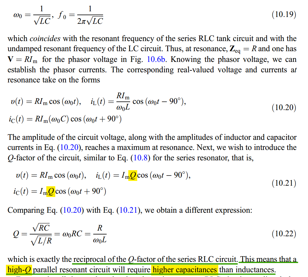
Parallel Resonant RLC
The parallel RLC resonator is a current divider circuit, driven by an alternating current source \(i_s(t)=I_m\cos\omega t\)
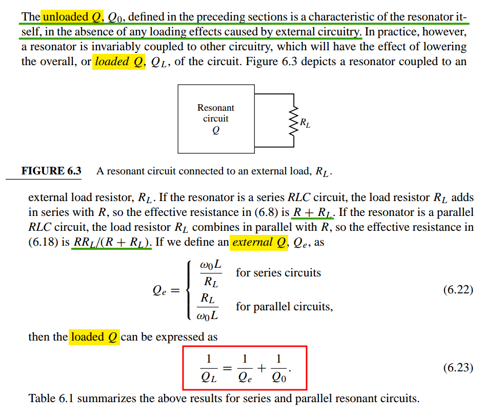
Loaded Q
unloaded Q, external Q, loaded Q
SRF (Self-Resonant Frequency)
[Understanding RF Inductor Specifications, https://www.ece.uprm.edu/~rafaelr/inel5325/SupportDocuments/doc671_Selecting_RF_Inductors.pdf]
[RFIC-GPT Wiki, https://wiki.icprophet.net/]
\[ f_\text{SRF} = \frac{1}{2\pi \sqrt{LC}} \] The SRF of an inductor is the frequency at which the parasitic capacitance of the inductor resonates with the ideal inductance of the inductor, resulting in an extremely high impedance. The inductance only acts like an inductor below its SRF

For choking applications, chose an inductor whose SRF is at or near the frequency to be attenuated
For other applications, the SRF should be at least 10 times higher than the operating frequency
it is more important to have a relatively flat inductance curve (constant inductance vs. frequency) near the required frequency
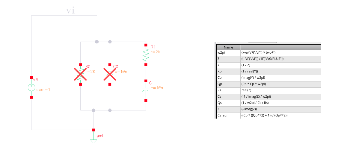
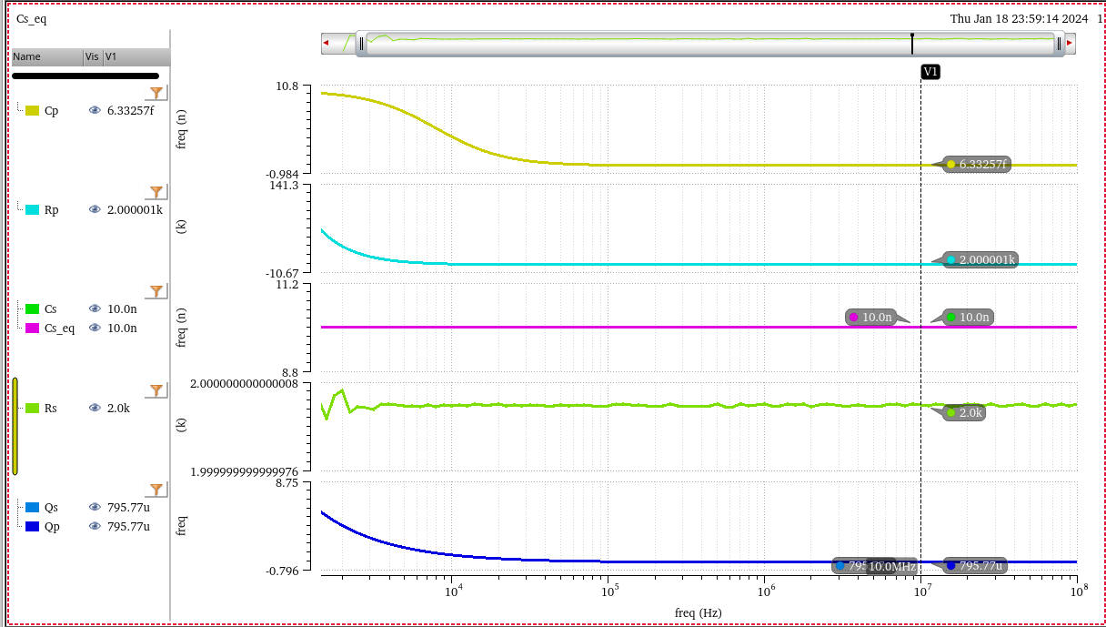
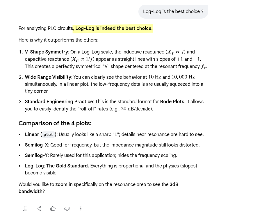
RLC inspection
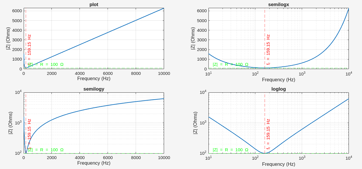
For analyzing RLC circuits, Log-Log is indeed the best choice.
1 | % Parameters |
reference
Pozar, David M. Microwave Engineering. 4th ed. Wiley, 2012. [pdf]
Hossein Hashemi, RF Circuits, [https://youtu.be/0f3yZMvD2Jg]
Resonant Circuits: Resonant Frequency and Q Factor [https://techweb.rohm.com/product/circuit-design/electric-circuit-design/18332/]
J. Nako, G. Tsirimokou, C. Psychalinos and A. S. Elwakil, "Approximation of First–Order Complex Resonators in the Frequency–Domain," in IEEE Access, vol. 13, pp. 54494-54503, 2025 [pdf]
How to generate complex poles without inductor? [https://a2d2ic.wordpress.com/2020/02/19/basics-on-active-rc-low-pass-filters/]
Visvesh Sathe. Resonant Clock Design for a Power-efficient, High-volume x86 -64 Microprocessor [https://ewh.ieee.org/r5/denver/sscs/Presentations/2012_05_Sathe.pdf]
RFInsights, A Journey from Resonance to Impedance Matching Chp. 1: Origin of Q-Factor The Deadly Beginnings, [https://www.rfinsights.com/concepts/quality-factor/]