Fixed-Point Signal Processing
why fixed-point arithmetic?
Because the dynamic range of the incoming physical signal is tightly controlled by an Analog Front End (AFE) using Automatic Gain Control (AGC), a massive floating-point dynamic range isn't necessary
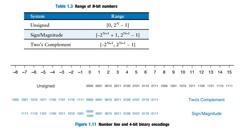
N-bit number
Harris, David Money, and Sarah L. Harris. Digital Design and Computer Architecture. 2nd ed. Morgan Kaufmann, 2013. [pdf]
integers
rational number
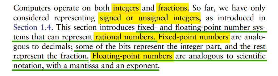
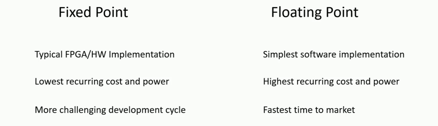
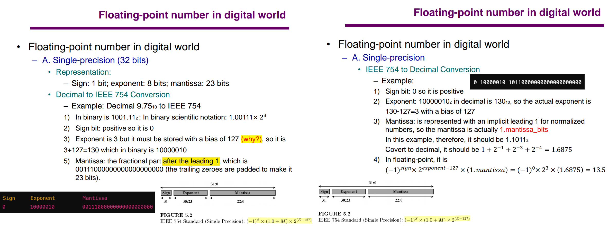
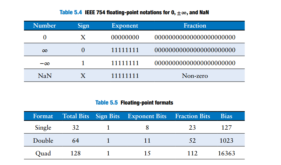
Floating-point Number in IEEE 754 Format
Floating-point data in IEEE 754 Format [https://github.com/IC-Design-Lab/IC-Design/blob/main/Training/Floating-point%20data%20in%20IEEE%20754%20Format.pdf]
Rajaraman, V.. “IEEE standard for floating point numbers.” Resonance 21 (2016): 11 - 30. [https://www.ias.ac.in/article/fulltext/reso/021/01/0011-0030]
IEEE Standard for Floating-Point Arithmetic [https://www-users.cse.umn.edu/~vinals/tspot_files/phys4041/2020/IEEE%20Standard%20754-2019.pdf]
Dennis Forbes. Understanding Floating-Point Numbers [https://dennisforbes.ca/blog/features/floating_point/understanding-floating-point-numbers/]
Bevan Baas, EEC 281 - VLSI Digital Signal Processing Winter 2025 [FLOATING POINT] [FLOATING POINT <---> FIXED POINT CONVERSION]

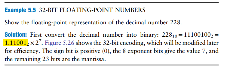
| 32-bit floating-point version 1 | store implicit leading one |  |
| 32-bit floating-point version 2 | discard implicit leading one |  |
| IEEE 754 floating point notation | biased exponent | 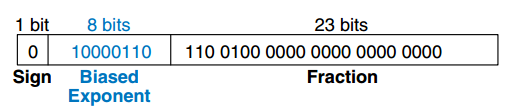 |
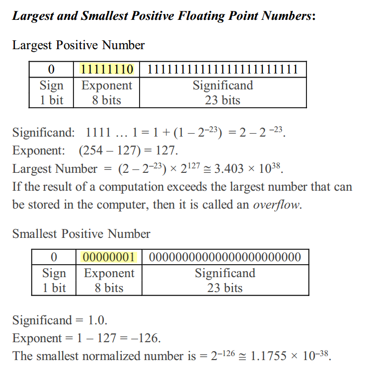 \[
\boxed{
\begin{aligned}
E=0 &: \quad \text{zero or subnormal},\\
1\le E\le254 &: \quad \text{normal finite number},\\
E=255 &: \quad \infty \text{ or NaN}.
\end{aligned}
}
\]
2's Complement
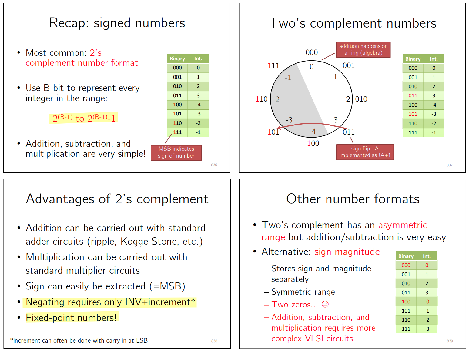
2's complement negative number
Flip all bits then Add 1
N-bit signed number \[ A = -M_{N-1}2^{N-1}+\sum_{k=0}^{N-2}M_k2^k \] Flip all bits \[\begin{align} A_{flip} &= -(1-M_{N-1})2^{N-1} +\sum_{k=0}^{N-2}(1-M_k)2^k \\ &= M_{N-1}2^{N-1}-\sum_{k=0}^{N-2}M_k2^k -2^{N-1}+\sum_{k=0}^{N-2}2^k \\ &= M_{N-1}2^{N-1}-\sum_{k=0}^{N-2}M_k2^k -1 \end{align}\]
Add 1 \[ A_- = A_{flip}+1 = M_{N-1}2^{N-1}-\sum_{k=0}^{N-2}M_k2^k = -A \]
negative number to 2's complement, interpreted as unsigned number \[ \text{S} = -2^{N-1} + \text{LSBs} \qquad \Longrightarrow \qquad \text{S} + 2^N = 2^{N-1} + \text{LSBs} \] For example -2 in 3-bit 2's complement is -2 + 8 = 6 = 3'110
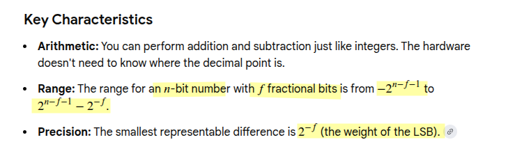
Fixed Point Number
Different notations can be used to represent different fractional formats
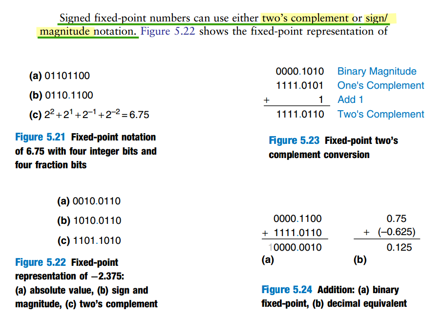
Q format; Wordlength, Fractionlength Format
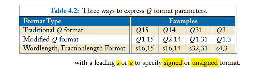
Different sources use slightly different \(Q\)-format conventions
\(Q1.3\) means that the
1 includes the sign bit. \[
Q1.3
=
\underbrace{1\text{ bit}}_{\text{sign / integer side}}
+
\underbrace{3\text{ fractional bits}}_{\text{fractional side}}
\] So it is a 4-bit two's-complement fixed-point
number:
1 | b3 . b2 b1 b0 |
Bit Shifts: Gain Scaling & Format Conversion
multiplication or format conversion
For a fixed-point number, distinguish the stored integer \(X\) from the represented value \(x\):
\[ \color{blue}\boxed{x=\frac{1}{2^F}X} \]
Here, \(F\) is the number of fractional bits. The binary point is an interpretation of the bits; it is not physically stored
1 | assign ted_s5_3 = (ted_s2_0 << 3); //s2.0 -> S5.3 |
The stored integer is multiplied by 8, while the fractional-bit count increases from zero to 3:
\[ Y=2^3 X,\qquad y=Y\,2^{-3}=X=x \]
For an input value of +1:
| Interpretation | Stored bits | Fractional bits | Represented value | |
|---|---|---|---|---|
Original S2.0 |
01 |
0 | 1 | |
Shifted result interpreted as S5.0 |
01000 |
0 | 8 | multiplication |
Shifted result interpreted as S5.3 |
01000 |
3 | 1 | format conversion |
Thus, the same shift can implement multiplication or a format conversion, depending on the output scale.
- SystemVerilog performs the bit operation
- your format convention determines its numerical meaning
1 | module Ar_B ( |
Let the unsigned stored codes be \(A\), \(B\), and \(r\). The intended values are:
\[ a=\frac{A}{2^4},\qquad b=\frac{B}{2^4} \]
so the desired output is:
\[ g=a\frac{r}{2^{12}}-b =\boxed{\frac{Ar-B\,2^{12}}{2^{16}}} \]
Consequently, the intermediate signals can be interpreted as follows:
| Signal | Stored integer | Fractional bits | Represented value |
|---|---|---|---|
A_tmp |
\(Ar\) | 16 | \(a(r/2^{12})\) |
B_tmp |
\(B\,2^{12}\) | 16 | \(b\) |
So_tmp |
\(\lvert Ar-B\,2^{12}\rvert\) | 16 | \(\lvert g\rvert\) |
So_int |
\(\left\lfloor\texttt{So}_\texttt{tmp}/2^{12}\right\rfloor\) | 4 | \(\lvert g\rvert\) quantized downward to steps of \(1/16\) |
Here, B << 12 converts the offset from 4
fractional bits to 16, preserving its represented value.
Likewise, So_tmp >> 12 converts the magnitude from
16 fractional bits to 4, discarding precision.
Let \(A\) denote the stored integer code. Since \(A\) has four fractional bits:
\[ a=\frac{A}{2^4} \]
The multiplication produces the stored integer:
\[ P=Ar \]
Its interpretation depends on the quantity we want it to represent:
| Intended quantity | Relationship to stored product \(P\) | Fractional bits |
|---|---|---|
| \(a\,r\) | \(a\,r=P/2^4\) | 4 |
| \(a(r/2^{12})\) | \(a(r/2^{12})=P/2^{16}\) | 16 |
The extra 12 fractional bits come from including the normalization by \(2^{12}\) in the interpretation. The multiplication itself does not add them automatically
Both interpretations are valid. For your complete calculation, the second makes the alignment particularly clear:
\[ g=\frac{\underbrace{Ar}_{\text{16 fractional bits}} -\underbrace{B\,2^{12}}_{\text{16 fractional bits}}}{2^{16}} \]
Here, both numerator terms are stored codes using the same scale, \(2^{-16}\)
right shift effect
1 | assign So_int = (So_tmp >> 12); |

| Signal | Stored integer | Fractional bits | Represented value |
|---|---|---|---|
So_int |
\(\left\lfloor\texttt{So}_\texttt{tmp}/2^{12}\right\rfloor\) | 4 | \(\lvert g\rvert\) quantized downward to steps of \(1/16\) |
left shift effect
1 | logic signed [5:0] obj_s6_3; // S6.3 |
The gain from obj_s6_3 to prop_s16_16 \[ \left\{ \begin{array}{cl} x&=\frac{X}{2^3} \\ y&=X 2^{10}\cdot \frac{1}{2^{16}}=\frac{X}{2^6}\end{array} \right. \qquad \Longrightarrow \qquad y=\frac{1}{2^3}\cdot x \] Generally, a left shift by \(k\) with input/output fractional-bit counts \(F_{\text{in}}\) and \(F_{\text{out}}\) gives:
\[ \boxed{y=2^{k+F_{\text{in}}-F_{\text{out}}}x} \]
provided no bits are lost
Programmable gain scaling
1 | module fixed_point_gain ( |
Let \(X\) be the signed input code and \(k\) the first-stage shift:
\[ x=X2^{-2}, \qquad y=(X2^k2^8)2^{-19} =\boxed{x\,2^{k-9}} \]
gain_sel |
Shift (k) | Numerical gain |
|---|---|---|
0 |
10 | 2 |
1 |
9 | 1 |
2 |
8 | 1/2 |
3 |
7 | 1/4 |
The widths are sufficient
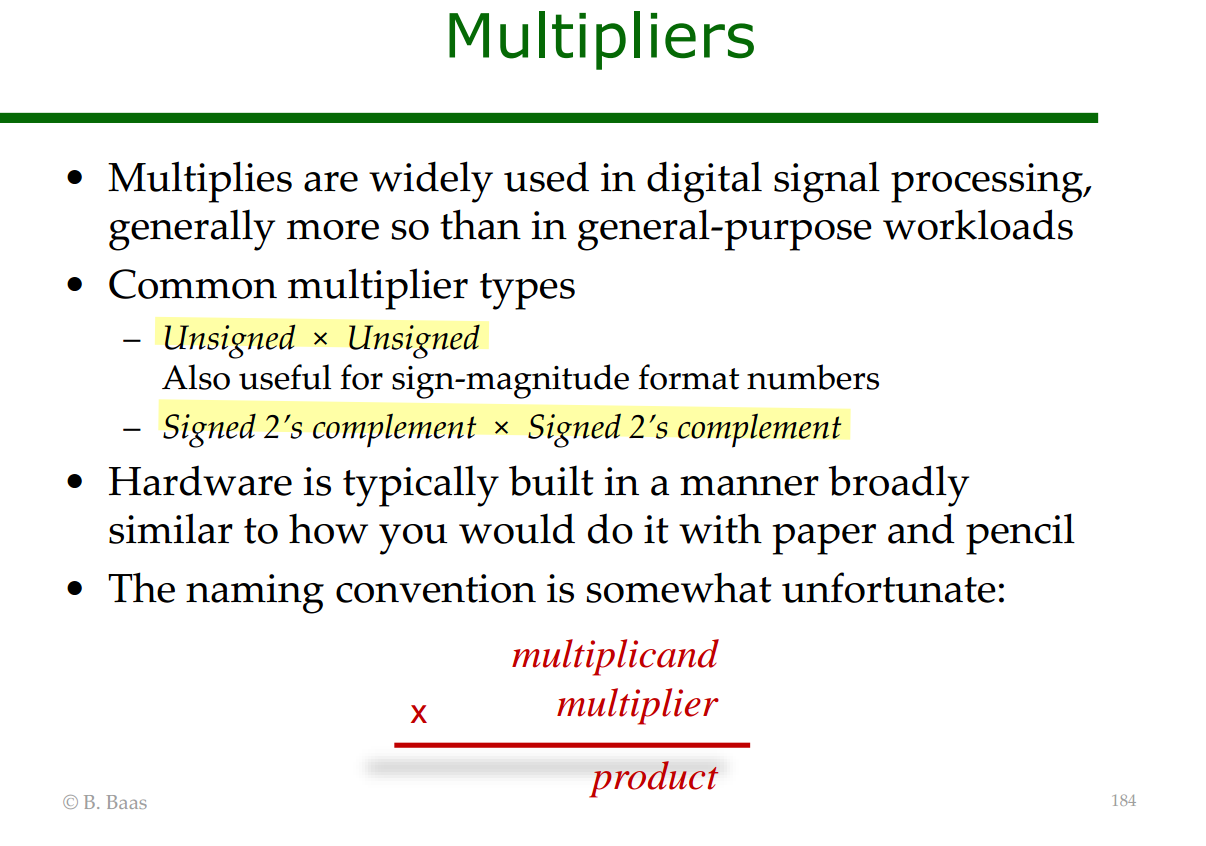
Multiplication
B. Baas, [HARDWARE MULTIPLIERS] [FIXED-INPUT MULTS] [MULTIPLICATION SCALING]
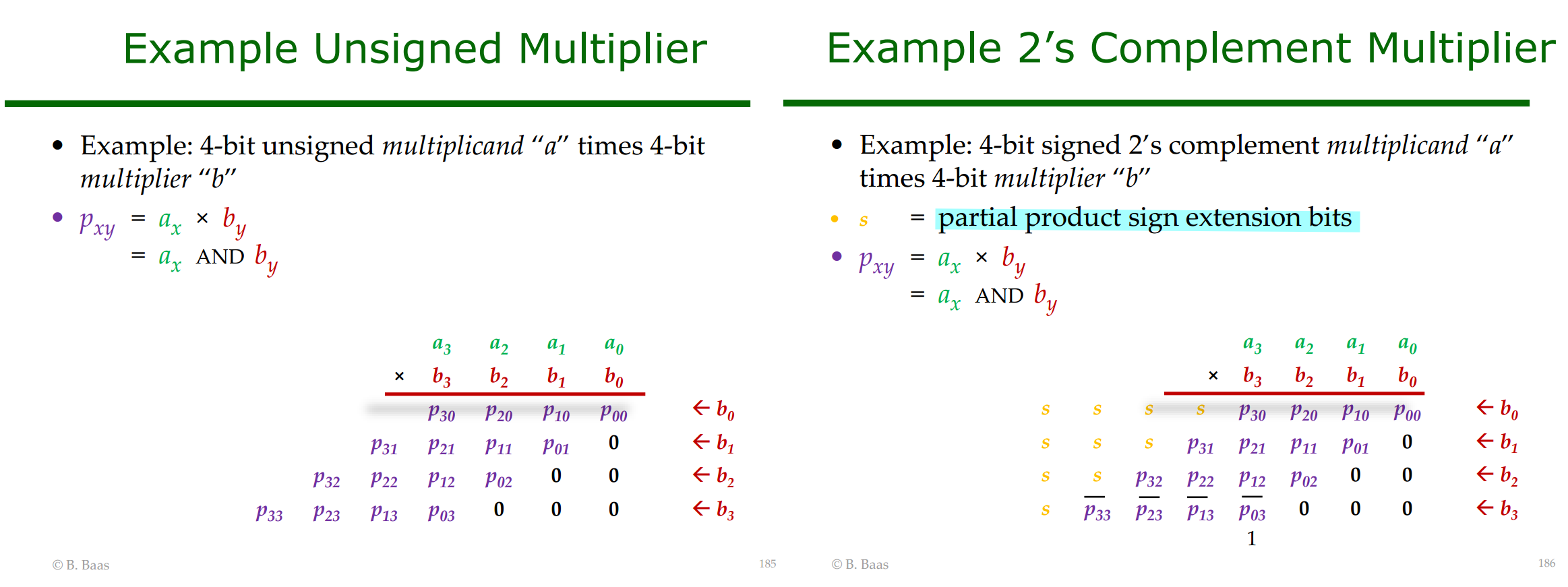
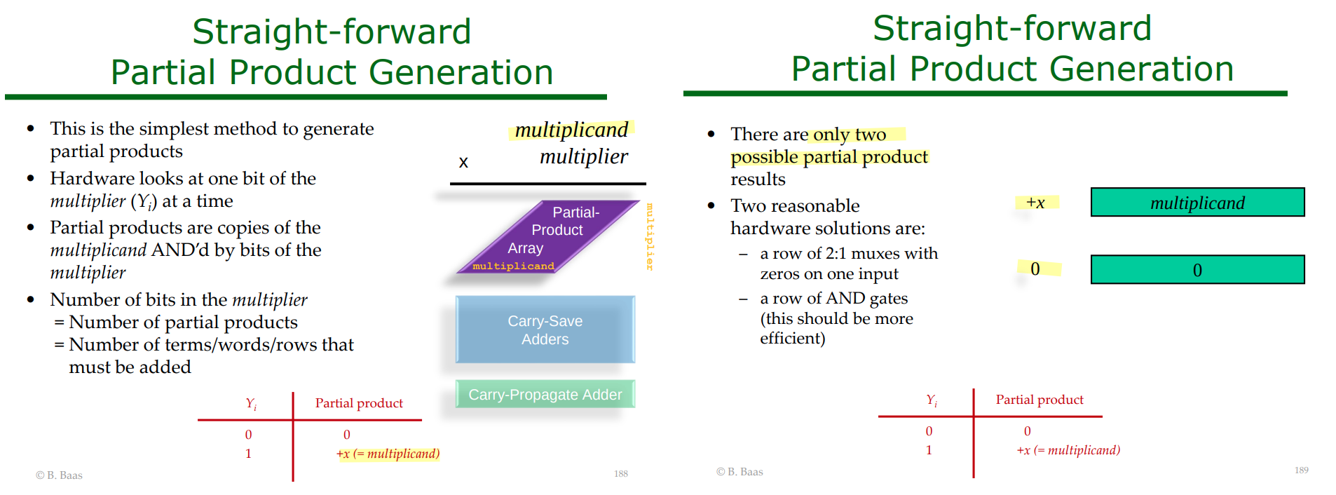
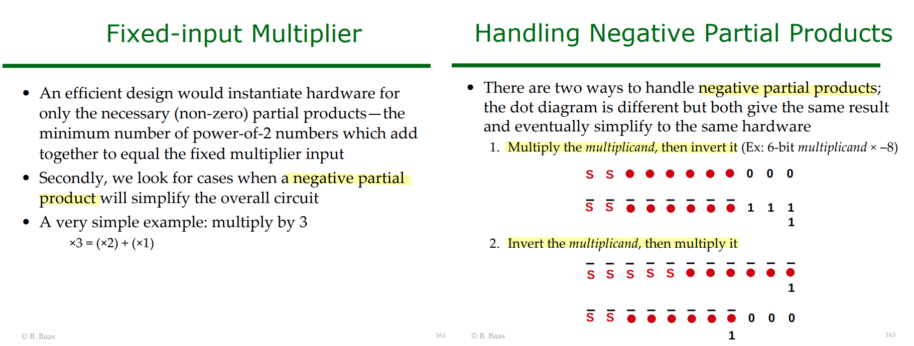
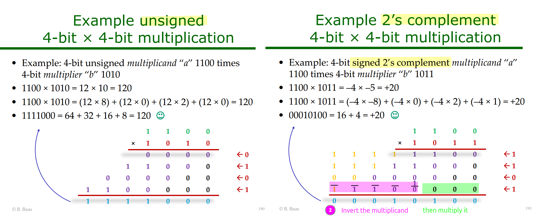
negate last partial product when multiplier[MSB]=1, i.e. multiplier is negative
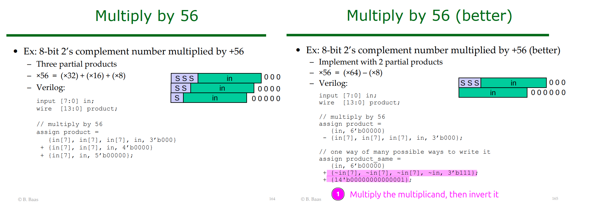
- Multiply the multiplicand, then invert it
- Invert the multiplicand, then multiply it
Multiplication Scaling
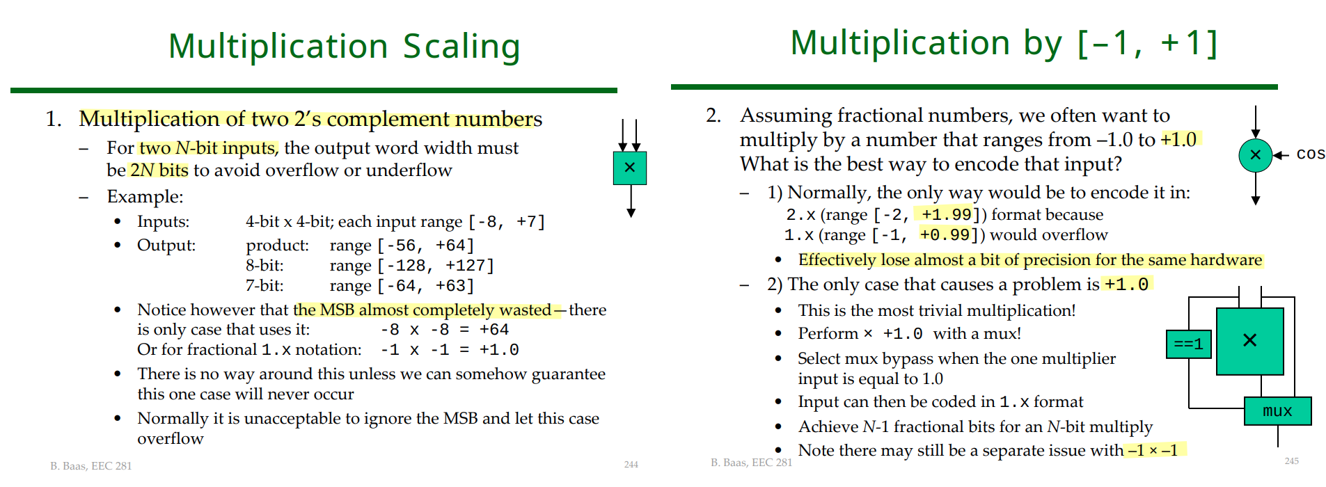
product wordlength
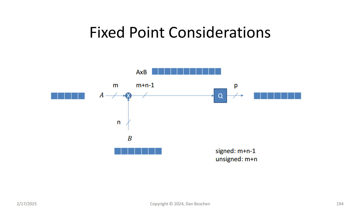
| Operands | Nominal full product width | |
|---|---|---|
| Unsigned | \(m+n\) | no overflow for any case |
| Signed fractional | \(m+n-1\) | with the exception of (-1)*(-1) case |
For signed fractional multiplication,
\[ Q1.(m-1)\times Q1.(n-1) \rightarrow Q1.(m+n-2) \]
Therefore, the total number of bits is
\[ 1+(m+n-2)=m+n-1. \]
There is one special corner case:
\[ (-1)\times(-1)=+1 \]
but a signed fractional format such as \(Q1.(m+n-2)\) has the range
\[ -1 \le x \le 1-2^{-(m+n-2)}, \]
so it cannot represent exactly \(+1\).
Therefore:
- Normally, signed fractional multiplication requires
\[ \boxed{m+n-1\text{ bits}} \]
- To guarantee no overflow even for
\[ (-1)(-1)=+1, \]
you need
\[ \boxed{m+n\text{ bits}} \]
Equivalently, if the operands have widths
\[ B_0+1 \quad\text{and}\quad B_1+1, \]
then the normal signed fractional product width is
\[ (B_0+1)+(B_1+1)-1 = \boxed{B_0+B_1+1}. \]
The only exception is again
\[ (-1)(-1)=+1 \]
Alan V Oppenheim, Ronald W. Schafer. Discrete-Time Signal Processing, 3rd edition
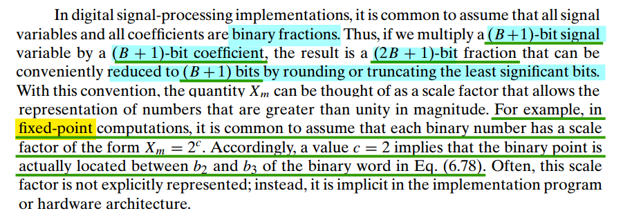
The useful fixed-point multiplication rule is \[ Q_{F_1} \times Q_{F_2} \qquad \Longrightarrow\qquad F_{\text{product}} = F_1 + F_2 \] where \(F_1\) and \(F_2\) are the numbers of fractional bits of the two operands
4-bit words are
1 | a = 0.100 -> 0100 |
Now temporarily ignore the binary point and multiply the integer bit patterns:
1 | 0100 (= 4) |
Multiplying an \(M\)-bit signed number by an \(N\)-bit signed number requires at most \(M+N\) signed bits to avoid overflow, assuming two’s-complement representation and that \(M,N\) include the sign bits.
The corner case is the most negative value multiplied by the most negative value:
\[ (-2^{M-1})(-2^{N-1})=+2^{M+N-2} \]
An \((M+N-1)\)-bit signed result can only represent positive values up to
\[ 2^{M+N-2}-1 \]
so it is one count short. Hence \(M+N\) bits are necessary for the full input range.
For example, two signed 3-bit numbers can each equal \(-4\):
\[ (-4)(-4)=16 \]
- Signed 5-bit range: \([-16,15]\) → overflow.
- Signed 6-bit range: \([-32,31]\) → fits.
For fixed-point multiplication, the fractional lengths also add:
\[ \boxed{W_{\text{out}}=M+N,\qquad F_{\text{out}}=F_a+F_b} \]
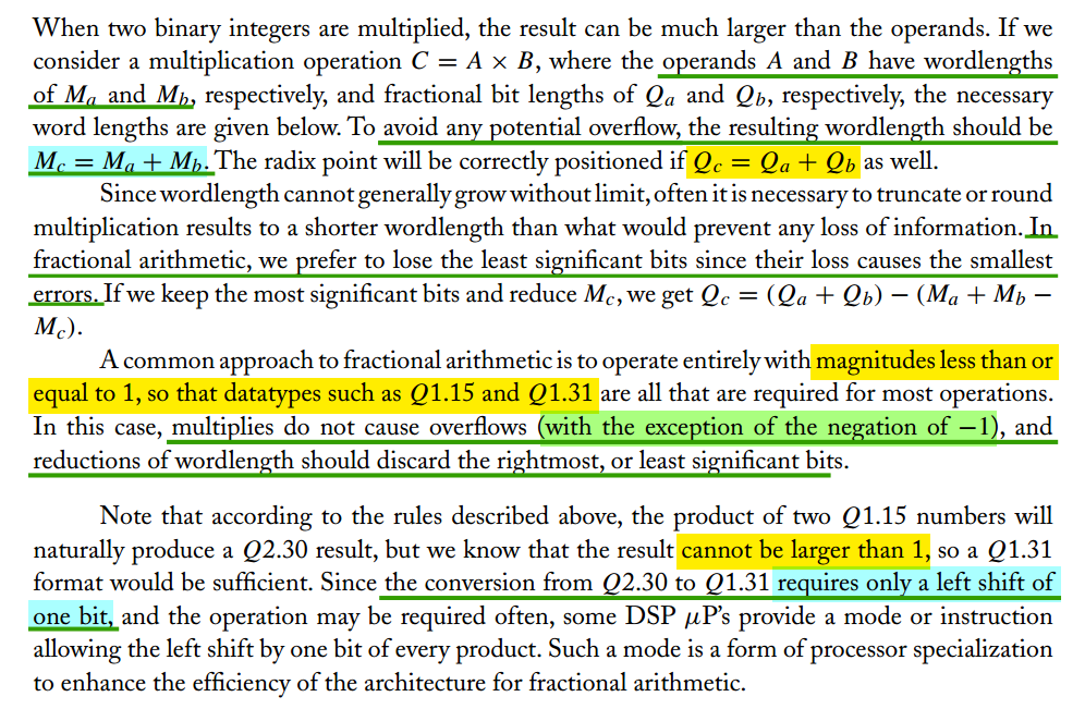
For the conversion \(Q2.30\rightarrow Q1.31\), both formats have 32 total bits:
| Format | Stored integer | Represented value |
|---|---|---|
| \(Q2.30\) | \(P\) | \(P\,2^{-30}\) |
| \(Q1.31\) after shifting left | \(2P\) | \((2P)\,2^{-31}\) |
Therefore, provided no overflow occurs,
\[ \boxed{x_{\text{after}}=(2P)\,2^{-31}=P\,2^{-30}=x_{\text{before}}} \]
For a 32-bit left shift converting \(Q2.30\rightarrow Q1.31\), overflow is avoided only when the original two MSBs are identical:
| Original two MSBs | Original \(Q2.30\) value \(x\) | Conversion |
|---|---|---|
00 |
\(0\le x<1\) | Safe |
11 |
\(-1\le x<0\) | Safe |
01 |
\(1\le x<2\) | Positive overflow |
10 |
\(-2\le x<-1\) | Negative overflow |
The shift discards the original MSB, and the second MSB becomes the new sign bit. When they match, the discarded bit is a redundant sign-extension bit, so the value is preserved after adjusting the fractional length
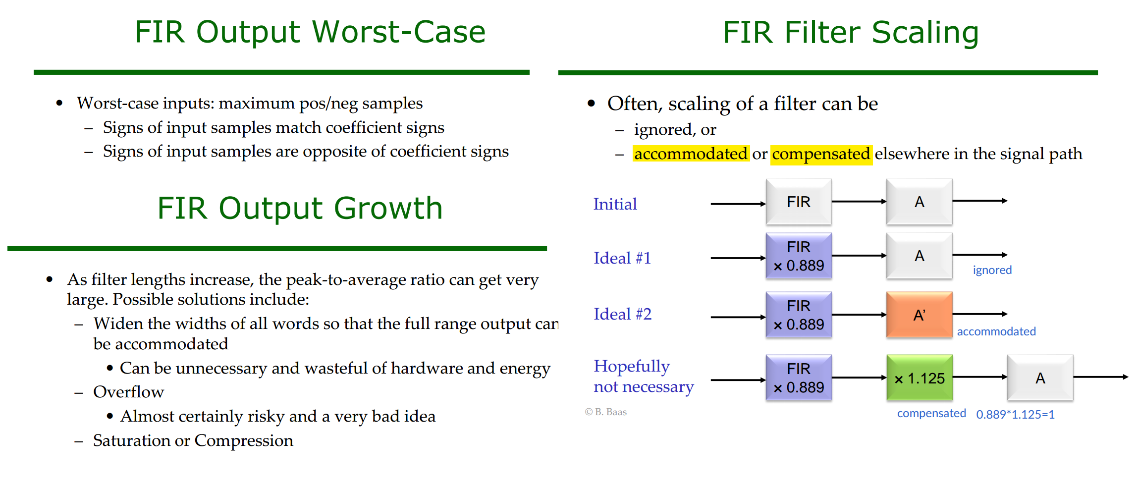
FIR Filter Scaling
Bevan Baas, EEC 281 - VLSI Digital Signal Processing Winter 2025 [FIR FILTER HARDWARE]
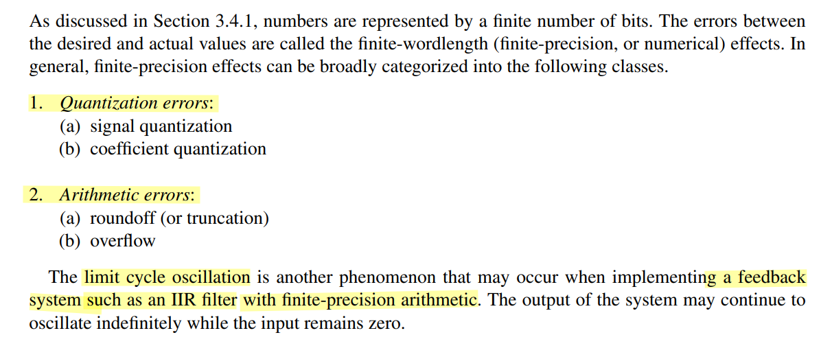
Finite-wordlength Effects
Tianshuang Qiu; Ying Guo, "7. Finite-Precision Numerical Effects in Digital Signal Processing," in Signal Processing and Data Analysis , De Gruyter, 2018, pp.236-248
Antoniou, Andreas. “Digital Signal Processing: Signals, Systems, and Filters.” (2005). [pdf]
Alan V Oppenheim, Ronald W. Schafer. Discrete-Time Signal Processing, 3rd edition
Bevan Baas, EEC 281 - VLSI Digital Signal Processing Winter 2025 [QUANTIZATION NOISE AS A FUNCTION OF WORD SIZE] [SATURATION&COMPRESSION] [ROUNDING]
Keshab K. Parhi, Chapter 11: Scaling and Round-off Noise [http://www.ece.umn.edu/users/parhi/SLIDES/chap11.pdf]
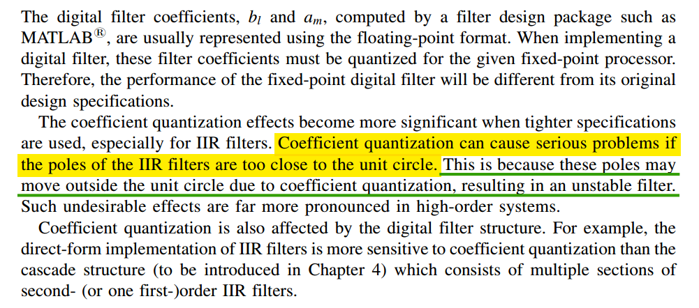
Coefficient Quantization
Roundoff Noise
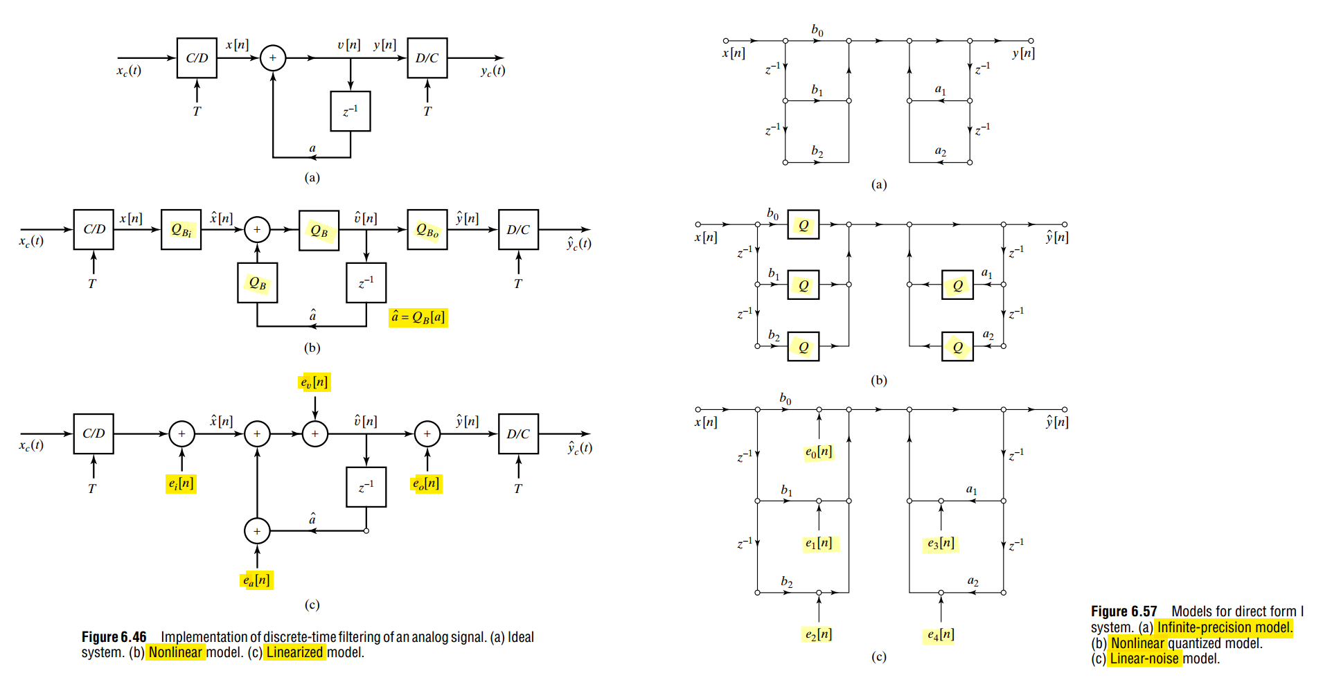
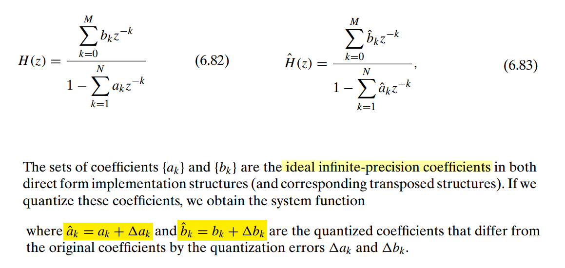
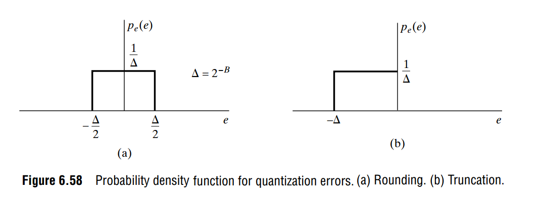
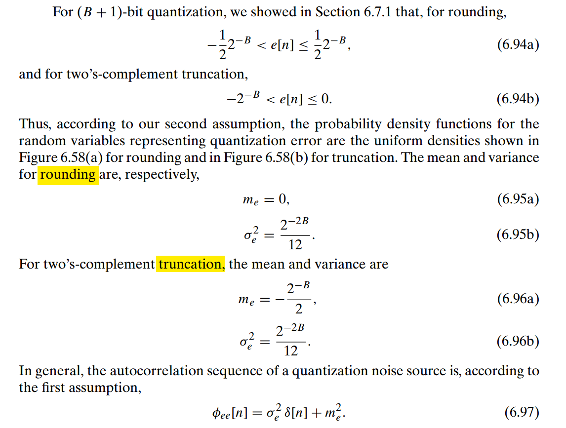
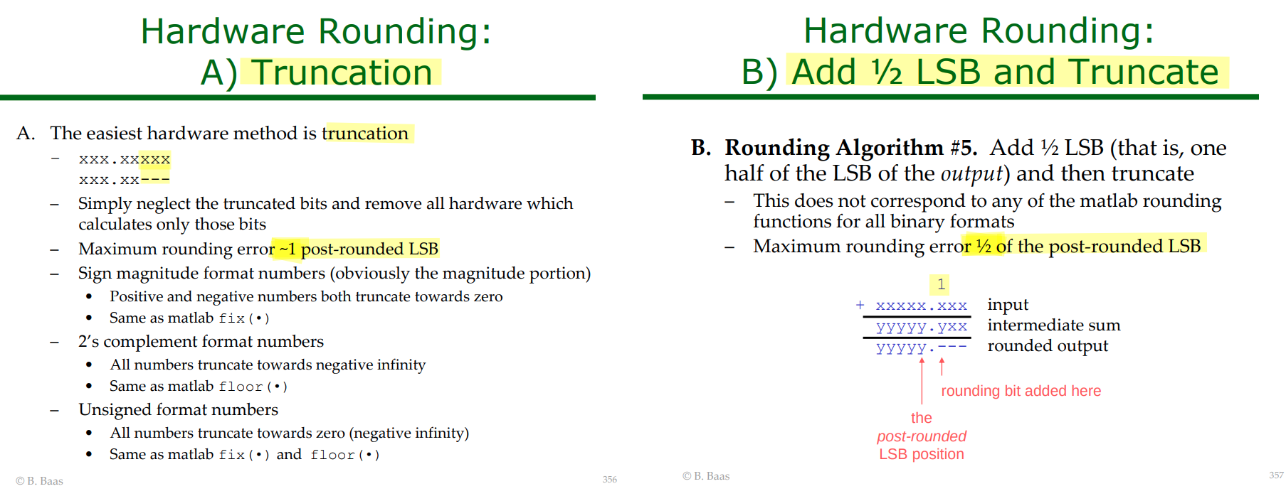
Direct-Form I (DF-I) implementation of a digital filter IIR
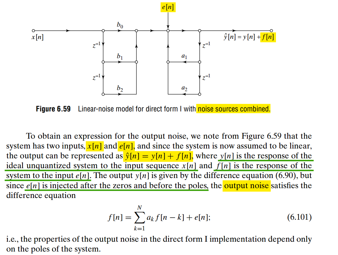
Equation (6.101) follows directly by writing the difference equation for the quantized system and subtracting the difference equation for the ideal system.
For the direct-form-I filter in Fig. 6.59, the ideal output satisfies
\[ y[n] = \sum_{k=0}^{M} b_k x[n-k] + \sum_{k=1}^{N} a_k y[n-k]. \tag{1} \]
The combined quantization noise \(e[n]\) is injected after the \(b_k\) section (zeros) and before the \(a_k\) feedback section (poles). Therefore the actual output \(\hat y[n]\) satisfies
\[ \hat y[n] = \sum_{k=0}^{M} b_k x[n-k] + \sum_{k=1}^{N} a_k \hat y[n-k] + e[n]. \tag{2} \]
The book defines
\[ \boxed{\hat y[n]=y[n]+f[n]} \]
where \(f[n]\) is the output component caused by the quantization noise
Substitute
\[ \hat y[n]=y[n]+f[n] \]
into (2):
\[ y[n]+f[n] = \sum_{k=0}^{M}b_kx[n-k] + \sum_{k=1}^{N}a_k\left(y[n-k]+f[n-k]\right) + e[n]. \]
Expand:
\[ y[n]+f[n] = \underbrace{ \sum_{k=0}^{M}b_kx[n-k] + \sum_{k=1}^{N}a_ky[n-k] }_{=\,y[n]} + \sum_{k=1}^{N}a_kf[n-k] + e[n]. \]
Using the ideal-system equation (1),
\[ y[n]+f[n] = y[n] + \sum_{k=1}^{N}a_kf[n-k] + e[n]. \]
Cancel \(y[n]\) from both sides:
\[ \boxed{ f[n] = \sum_{k=1}^{N}a_k f[n-k]+e[n] } \tag{6.101} \]
That is exactly Eq. (6.101).
Why do the \(b_k\) coefficients disappear?
This is the important point.
The signal path is
\[ x[n] \rightarrow \underbrace{B(z)}_{\text{zeros}} \rightarrow \boxed{+\,e[n]} \rightarrow \underbrace{\frac{1}{A(z)}}_{\text{poles}} \rightarrow \hat y[n]. \]
The noise is inserted after \(B(z)\), so it never passes through the zeros. It only passes through the all-pole feedback section.
In the \(z\)-domain, Eq. (6.101) gives
\[ F(z) = \sum_{k=1}^{N}a_kz^{-k}F(z)+E(z). \]
Thus,
\[ F(z) \left( 1-\sum_{k=1}^{N}a_kz^{-k} \right) = E(z), \]
and therefore
\[ \boxed{ \frac{F(z)}{E(z)} = \frac{1} {1-\displaystyle\sum_{k=1}^{N}a_kz^{-k}} } \]
So the output quantization-noise transfer function contains only the poles, which is what the sentence immediately after (6.101) means.
For the second-order example in the figure,
\[ \boxed{ f[n]=a_1f[n-1]+a_2f[n-2]+e[n]. } \]
The coefficients \(b_0,b_1,b_2\) have no effect on \(f[n]\) because \(e[n]\) is injected after that part of the filter.
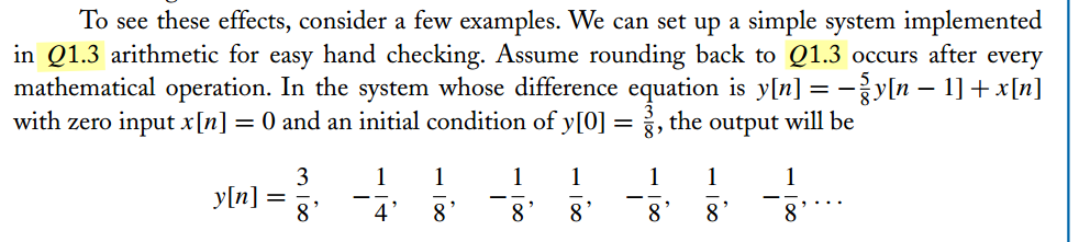
Limit Cycles in feedback system
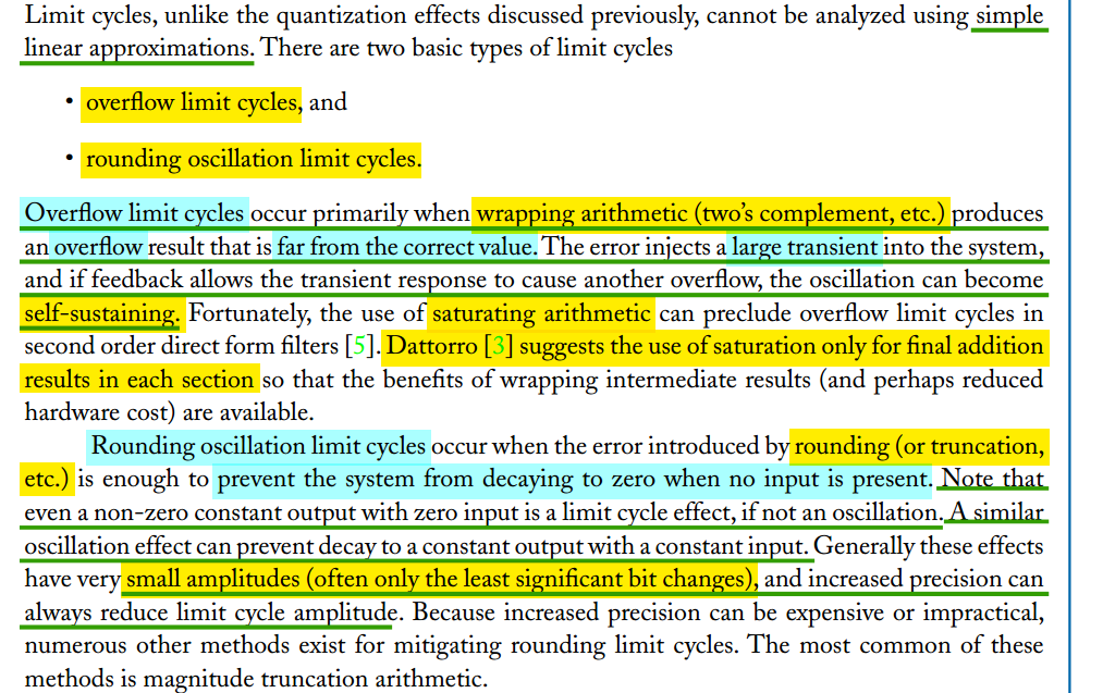
Limit Cycles Owing to Round-off & Truncation
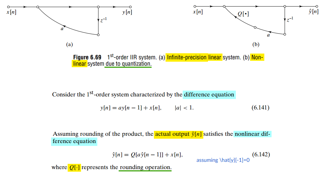
For infinite-precision linear system \(y[n] = a y[n-1] + x[n],\)
with zero initial condition \(y[-1]=0\), the impulse response is \[ y[n] = \frac{7}{8} a^n u[n] \] because after the impulse at \(n=0\), we have \(x[n]=0\) for all \(n\ge 1\).
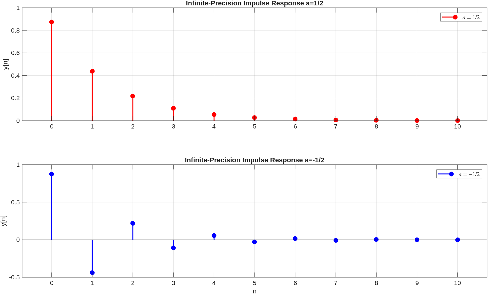
For nonlinear system \(\hat{y}[n] = Q[a \hat{y}[n-1]] + x[n],\)
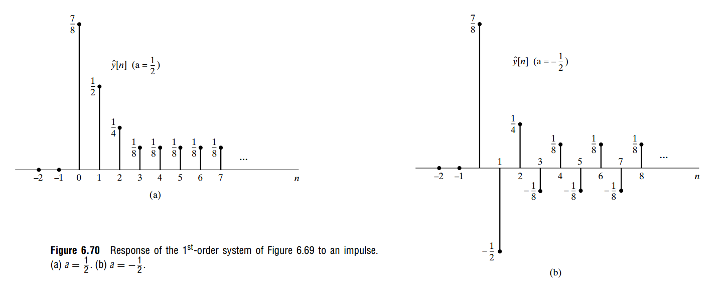
The nonzero steady oscillation or constant value is created entirely by the rounding operation (nonlinear) \(Q[\cdot]\)
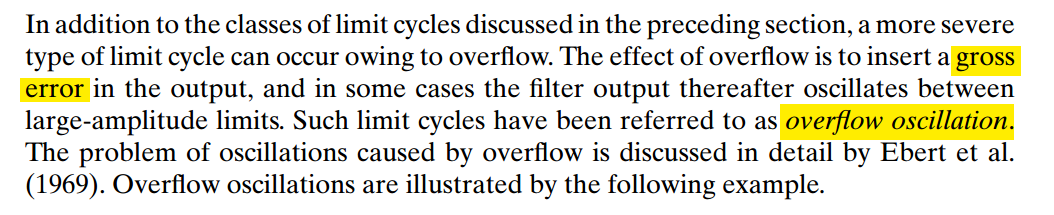
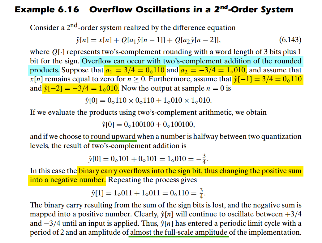
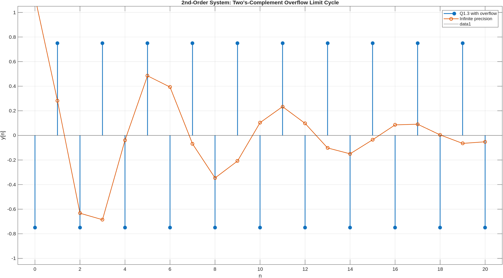
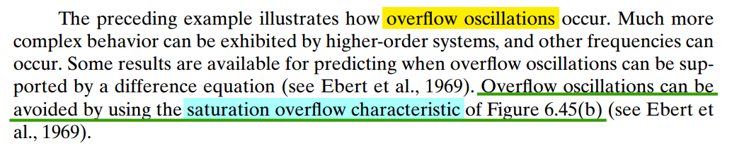
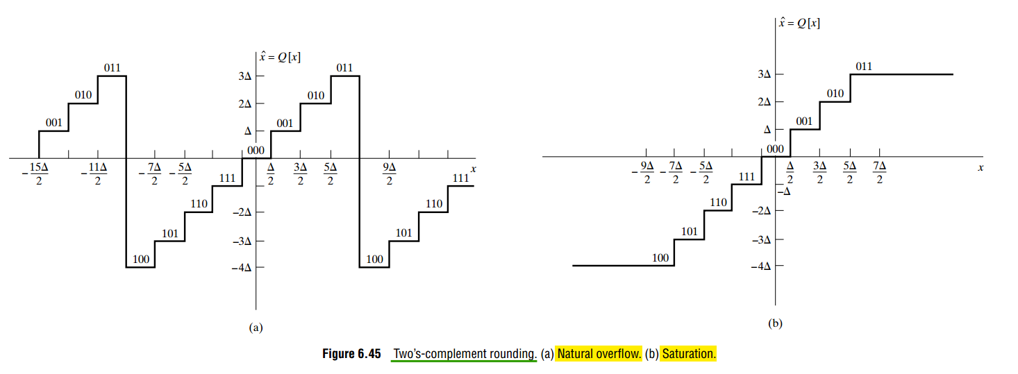
Limit Cycles Owing to Overflow
1 | %% Parameters |
1 | //------------------------------------------------------------------------- |
Avoiding Limit Cycles
The suppression of limit cycles is a broad topic with all the complexity to be expected in a nonlinear system behavior.
The most basic tools of saturation arithmetic and magnitude truncation — rounding rounds toward zero

Saturation Arithmetic & Scaling of Signals
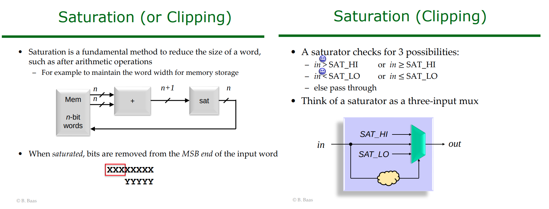
Saturation arithmetic prevents overflow by clipping the results to a maximum value
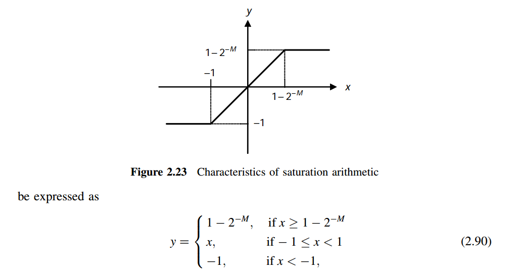
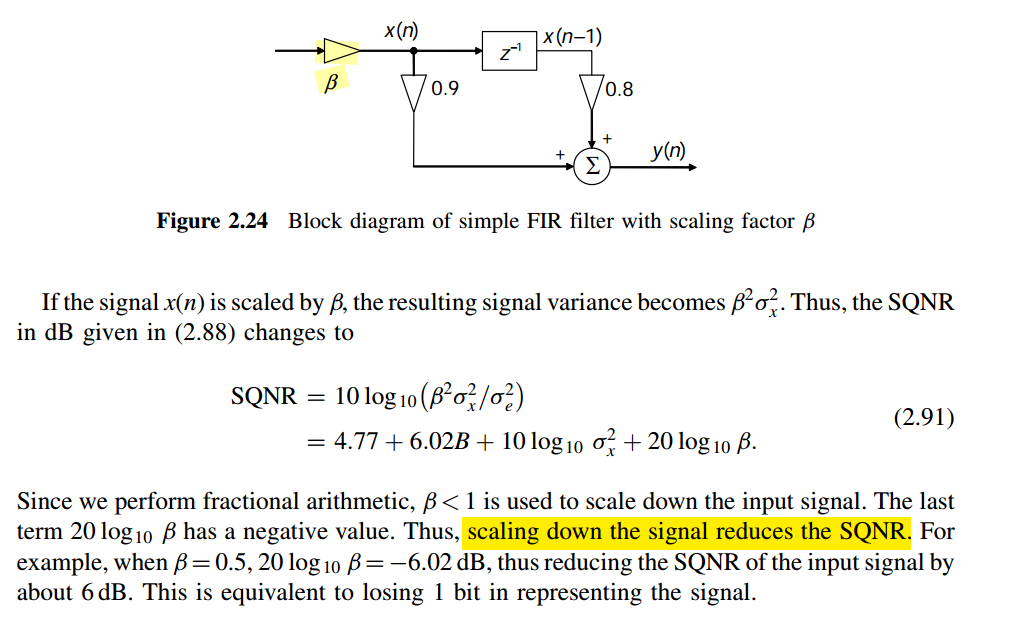
The most effective technique in preventing overflow is by scaling down the signal
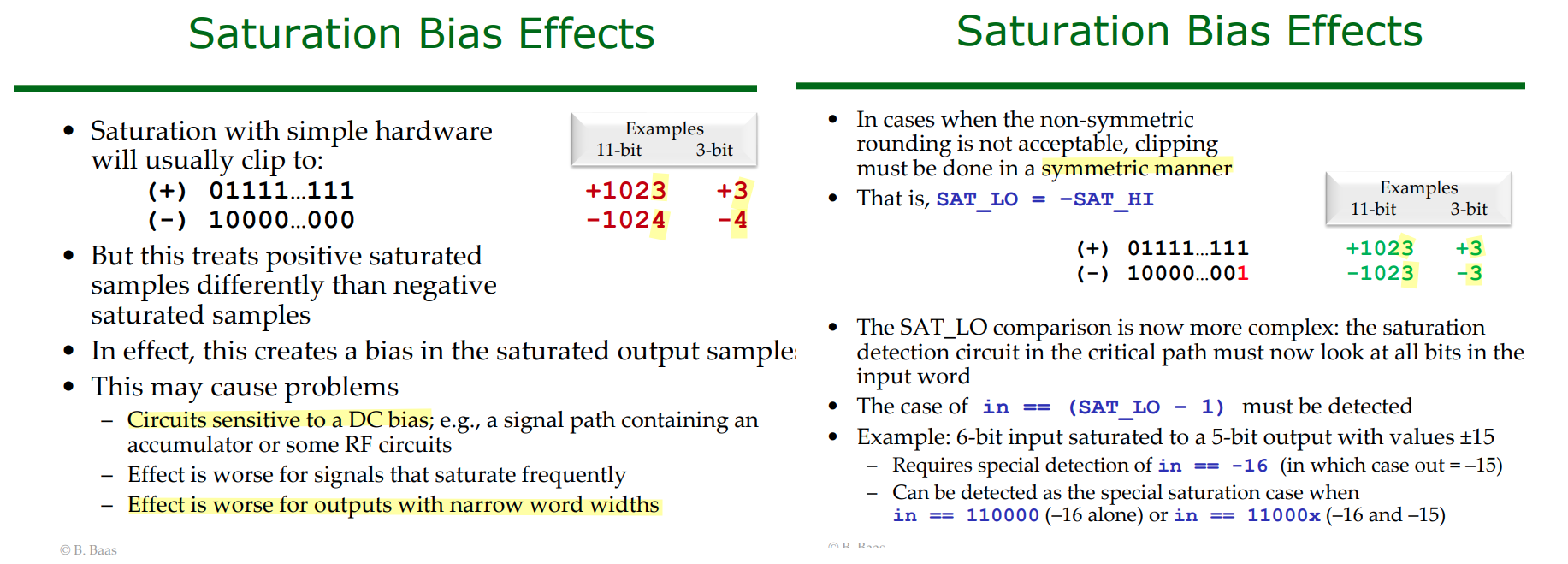
Saturation Bias Effects
One-Hot and Thermometer (Unary) codes
An N-bit binary input represents \(2^{N}\) unique values (from 0 to \(2^N - 1\))
Converting this input requires a \(2^{N}\)-bit width for One-Hot encoding, but only a \((2^N - 1)\)-bit width for Thermometer Code, as the value zero is represented by all zeros
| Decimal | Binary (\(N=3\)) | One-Hot (\(2^3 = 8\)) bits) | Thermometer (\(2^3 - 1 = 7\)) bits) |
|---|---|---|---|
| 0 | 000 |
00000001 |
0000000 |
| 1 | 001 |
00000010 |
0000001 |
| 2 | 010 |
00000100 |
0000011 |
| 3 | 011 |
00001000 |
0000111 |
| 4 | 100 |
00010000 |
0001111 |
| 5 | 101 |
00100000 |
0011111 |
| 6 | 110 |
01000000 |
0111111 |
| 7 | 111 |
10000000 |
1111111 |
reference
Padgett, Wayne T. and David V. Anderson. "Fixed-Point Signal Processing." Synthesis Lectures on Signal Processing (2009).
Alan V Oppenheim, Ronald W. Schafer. Discrete-Time Signal Processing, 3rd edition
Jabbour, Chadi, etc.. "Digitally enhanced mixed signal systems." IEEE International Symposium on Circuits and Systems (ISCAS). 2019.
Sen M. Kuo. Real-Time Digital Signal Processing: Fundamentals, Implementations and Applications, 3rd Edition. John Wiley & Sons 2013 [pdf]
Taylor, Fred. Digital filters: principles and applications with MATLAB. John Wiley & Sons, 2011
D. Markovic and R. W. Brodersen, DSP Architecture Design Essentials, Springer, 2012.
X. Yang, Integrated Circuit Design: IC Design Flow and Project-Based Learning, 1st edition. Boca Raton: CRC Press, 2024 [repo]
K.K. Parhi, VLSI Digital Signal Processing Systems: Design and Implementation, Wiley, NY 1999
Shoab Ahmed Khan, Digital Design of Signal Processing Systems: A Practical Approach (Wiley, 2011)
Bevan Baas, EEC281 VLSI Digital Signal Processing, [https://www.ece.ucdavis.edu/~bbaas/281/]
Mark Horowitz. EE371: Advanced VLSI Circuit Design Spring 2006-2007 [https://web.stanford.edu/class/archive/ee/ee371/ee371.1066/]
Tinoosh Mohsenin. CMPE 691: Digital Signal Processing Hardware Implementation [https://userpages.cs.umbc.edu/tinoosh/cmpe691/]
Keshab K. Parhi [http://www.ece.umn.edu/users/parhi/]
謝秉璇. 2019 積體電路設計導論 [link]
Jason Sachs. Understanding and Preventing Overflow (I Had Too Much to Add Last Night) [https://www.embeddedrelated.com/showarticle/532.php]
—. Round Round Get Around: Why Fixed-Point Right-Shifts Are Just Fine [https://www.embeddedrelated.com/showarticle/1015.php]
—. How to Build a Fixed-Point PI Controller That Just Works: Part I [https://www.embeddedrelated.com/showarticle/121.php]
—. How to Build a Fixed-Point PI Controller That Just Works: Part II [https://www.embeddedrelated.com/showarticle/123.php]
AHMED SHAHEIN, Fixed-Point Simulation in GNU Octave—Without MATLAB [https://www.dsprelated.com/showarticle/1786.php]
A. Antoniou, "On the roots of digital signal processing. Part I," in IEEE Circuits and Systems Magazine, vol. 7, no. 1, pp. 8-18, First Quarter 2007
—, "Feature - On the roots of digital signal processing - Part II," in IEEE Circuits and Systems Magazine, vol. 7, no. 4, pp. 8-19, Fourth Quarter 2007
Hideo Okawara's Mixed Signal Lecture Series [https://tomverbeure.github.io/2024/01/06/Hideo-Okawara-Mixed-Signal-Lecture-Series.html]
Jeffrey Walling, DSP to ASIC Block [https://youtube.com/playlist?list=PLP4ZmM6GPueNEdnLhgkdr8_X8dSizUwMs]
Abdur Rafae Haqqani, Embedded Systems / FPGA Blogs On Request Rounding, dither and saturation when you cut word width in FPGA DSP. [https://rafae1130.github.io/posts/on-request/fractions-in-fpga.html]