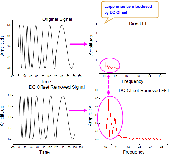
Performing FFT to a signal with a large DC offset would
often result in a big impulse around frequency 0 Hz, thus masking out
the signals of interests with relatively small amplitude.
One method to remove DC offset from the original signal before
performing FFT
Subtracting the Mean of Original Signal
You can also not filter the input, but set zero to the zero frequency
point for FFT result.
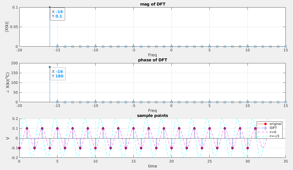
Nyquist component
If we go back to the definition of the DFT \[
X(N/2)=\sum_{n=0}^{N-1}x[n]e^{-j2\pi
(N/2)n/2}=\sum_{n=0}^{N-1}x[n]e^{-j\pi n}=\sum_{n=0}^{N-1}x[n](-1)^n
\] which is a real number.
The discrete function \[
x[n]=\cos(\pi n)
\] is always \((-1)^n\) for
integer \(n\)
One general sinusoid at Nyquist and has phase shift \(\theta\), this is \(T=2\) and \(T_s=1\)
Moreover \(B \cdot (-1)^n = B\cdot \cos(\pi
n)\), then \[
B\cdot \cos(\pi n) = A \cdot \cos(\pi n + \theta)
\] We can NOT distinguish one from another.
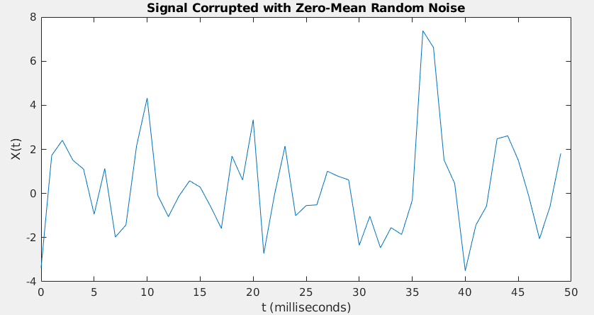
Fs = 1000;            % Sampling frequency
T = 1/Fs;             % Sampling period
L = 1500;             % Length of signal
t = (0:L-1)*T;        % Time vector
S = 0.7*sin(2*pi*50*t) + sin(2*pi*120*t);
X = S + 2*randn(size(t));
figure(1)
plot(1000*t(1:50),X(1:50))
title('Signal Corrupted with Zero-Mean Random Noise')
xlabel('t (milliseconds)')
ylabel('X(t)')

figure(2)
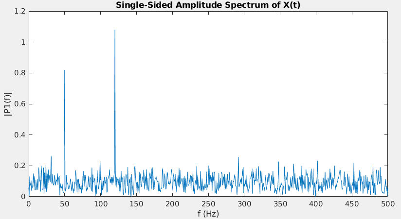
Y = fft(X);
P2 = abs(Y/L);      %!!! two-sided spectrum P2.
P1 = P2(1:L/2+1);   %!!! single-sided spectrum P1
P1(2:end-1) = 2*P1(2:end-1);	% exclude DC and Nyquist freqency
f = Fs*(0:(L/2))/L;
figure(2)
plot(f,P1)
title('Single-Sided Amplitude Spectrum of X(t)')
xlabel('f (Hz)')
ylabel('|P1(f)|')
DC and Nyquist bins are special because they have no mirror
twin:
Frequency Bin
Location in FFT
Mirror Twin?
Action for Single-Sided Plot
DC (0 Hz)
First element
None
Leave alone (Multiply by 1)
Positive Freqs
First half
Has a twin in the second half
Double it (Multiply by 2)
Nyquist ((F_s/2))
Exact middle
None (Shared)
Leave alone (Multiply by 1)
Negative Freqs
Second half
Discarded entirely
Dropped
Doubling them would double-count their energy and give you an
artificially inflated amplitude.
Alternative View
The direct current (DC) bin (\(k=0\)) and the bin at \(k=N/2\), i.e., the bin that corresponds to
the Nyquist frequency are purely real and unique.
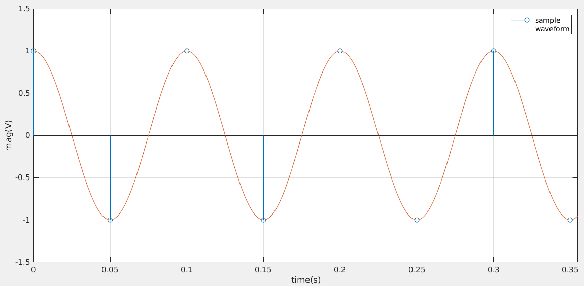
sinusoidal waveform with \(10Hz\),
amplitude 1 is \(cos(2\pi f_c t)\). The
plot is shown as below with sampling frequency is \(20Hz\)
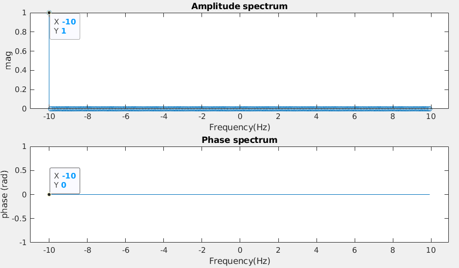
Amplitude and Phase spectrum, sampled with \(f_s=20\) Hz
The FFT magnitude of \(10Hz\) is
1 and its phase is 0 as shown as
above, which proves the DFT and IDFT.
Caution: the power of FFT is related to samples (DFT
Parseval's theorem), which may not be the power of continuous signal.
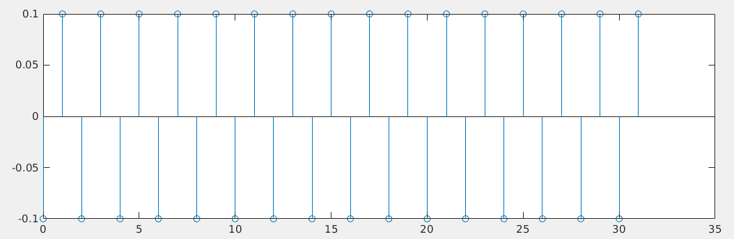
The average power of samples is ([1 -1 1 -1 -1 1 ...]) is
1, that of corresponding continuous signal is \(\frac{1}{2}\).
Power spectrum derived from FFT provide information of samples, i.e.
1
Moreover, average power of sample [1 -1 1 -1 1 ...] is same with DC
[1 1 1 1 ...].
After successful compilation, you can run the simulation using the
vvp runtime engine:
1
vvp sim.vvp +VCDFILE=output.vcd
+VCDFILE=output.vcd: This is the custom plusarg.
"$value$plusargs("VCDFILE=%s", filename)": The simulator
searches for +VCDFILE=. It extracts the string after the
= sign and saves it into the filename
variable.
$dumpfile(filename): This opens a VCD file named
output.vcd.
$dumpvars(0, DUT): This dumps all signals inside the
module instance named DUT and everything below it
1
2
3
4
5
6
7
8
string filename;
initialbegin if ($value$plusargs("VCDFILE=%s",filename)) begin $dumpfile(filename); $dumpvars(0, DUT); end end
For use with --batch, perform automatic expansions as a
stand-alone tool. This sets up the appropriate Verilog mode environment,
updates automatics with M-x verilog-auto on all command-line files, and
saves the buffers. For proper results, multiple filenames need to be
passed on the command line in bottom-up order.
-f verilog-auto-save-compile
Update automatics with M-x verilog-auto, save the buffer, and
compile
Emacs
--no-site-file
Another file for site-customization is site-start.el.
Emacs loads this before the user's init file
(.emacs, .emacs.el or
.emacs.d/.emacs.d). You can inhibit the loading of this
file with the option --no-site-file
--batch
The command-line option --batch causes Emacs to run
noninteractively. The idea is that you specify Lisp programs to run;
when they are finished, Emacs should exit.
--load, -l FILE, load Emacs Lisp FILE using the load
function;
--funcall, -f FUNC, call Emacs Lisp function FUNC with
no arguments
-f FUNC
--funcall, -f FUNC, call Emacs Lisp function FUNC with
no arguments
--load, -l FILE
--load, -l FILE, load Emacs Lisp FILE using the load
function
Verilog-mode is a standard part of GNU Emacs as of 22.2.
multiple directories
AUTOINST only search in the file's directory
default.
You can append below verilog-library-directories for
multiple directories search
1 2 3
// Local Variables: // verilog-library-directories:("." "subdir" "subdir2") // End:
plusargs are command-line switches supported by the
simulator. As per SystemVerilog LRM arguments beginning with the
+ character will be available using the
$test$plusargs and $value$plusargsPLI
APIs.
1 2 3
$test$plusargs (user_string)
$value$plusargs (user_string, variable)
1 2 3 4 5 6 7 8 9 10 11 12 13 14 15 16
// tb.v module tb; int a; initialbegin if($test$plusargs("RUNSIM")) begin $display("There is RUNSIM plusargs"); endelsebegin $display("There is NO $test$plusargs"); end if($value$plusargs("SEED=%d",a)) begin $display("SEED=%d",a); endelsebegin $display("There is NO $value$plusargs"); end end endmodule
compile
1 2
$ vlib work $ vlog -sv tb.v
simulate (QuestaSim)
without plusargs
1
$ vsim work.tb -c -do "run; exit"
1 2 3 4 5 6 7 8 9
# // # Loading sv_std.std # Loading work.tb(fast) # run # There is NO $test$plusargs # There is NO $value$plusargs # exit # End time: 13:04:23 on Jun 04,2022, Elapsed time: 0:00:01 # Errors: 0, Warnings: 0
Article (20488135) Title: Selecting Different Delay Modes in GLS
(RAK)
Article (20447759) Title: Gate Level Simulation (GLS): A Quick Guide
for Beginners
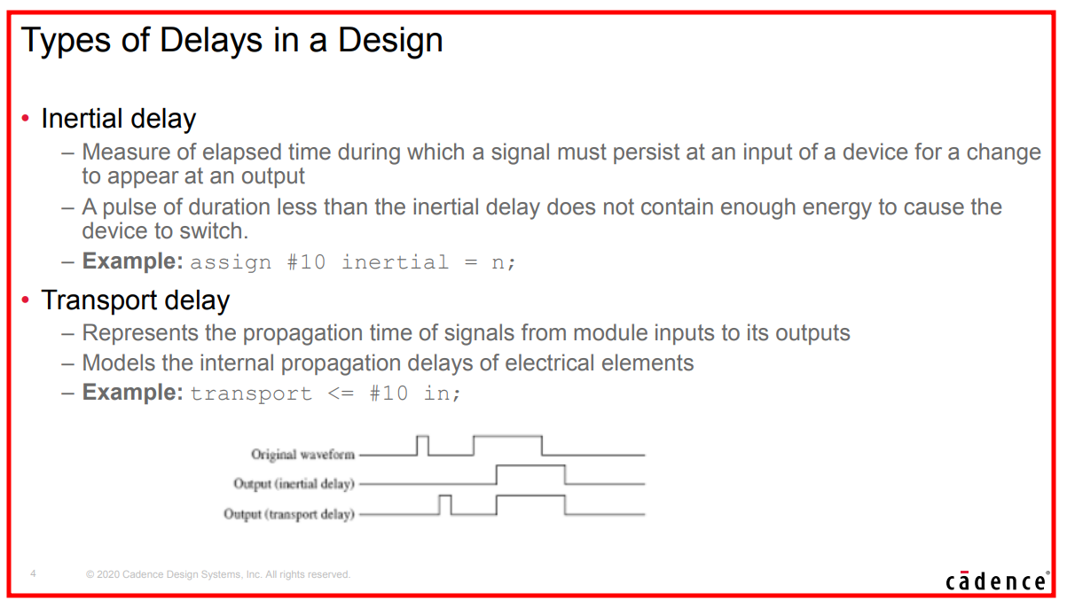
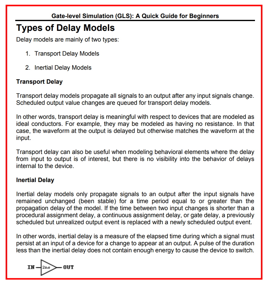
Inertial delay
Inertial delay models are simulation delay models that filter pulses
that are shorted than the propagation delay of Verilog gate
primitives or continuous assignments
(assign #5 y = ~a;)
COMBINATIONAL LOGIC ONLY !!!
Inertial delays swallow glitches
sequential logic implemented with procedure
assignments DON'T follow the rule
reg in; ///////////////////////////////////////////////////// wire out; assign #2.5 out = in; ///////////////////////////////////////////////////// initialbegin in = 0; #16; in = 1; #2; in = 0; #10; in = 1; #4; in = 0; end
//////////// combination logic //////////////////////// always @(*) #2.5 out = in; /////////////////////////////////////////////////////// /* the above code is same with following code always @(*) begin #2.5; out = in; end */ initialbegin in = 0; #16; in = 1; #2; in = 0; #10; in = 1; #4; in = 0; end
alwaysbegin clk = 0; #5; foreverbegin clk = ~clk; #5; end end //////////// sequential logic ////////////////// always @(posedge clk) #2.5 out <= in; /////////////////////////////////////////////// initialbegin in = 0; #16; in = 1; #2; in = 0; #10; in = 1; end
initialbegin #50; $finish(); end
endmodule
As shown above, sequential logic DON'T follow inertial delay
Transport delay
Transport delay models are simulation delay models that pass all
pulses, including pulses that are shorter than the propagation delay of
corresponding Verilog procedural assignments
Transport delays pass glitches, delayed in time
Verilog can model RTL transport delays by adding explicit
delays to the right-hand-side (RHS) of a nonblocking
assignment
reg in; reg out; /////////////// nonblocking assignment /// always @(*) begin out <= #2.5 in; end ///////////////////////////////////////// initialbegin in = 0; #16; in = 1; #2; in = 0; #10; in = 1; #4; in = 0; end
reg in; reg out; /////////////// blocking assignment /// always @(*) begin out = #2.5 in; end ///////////////////////////////////////// initialbegin in = 0; #16; in = 1; #2; in = 0; #10; in = 1; #4; in = 0; end
initialbegin #50; $finish(); end
endmodule
It seems that new event is discarded before previous
event is realized.
clocking block in
SystemVerilog
Assignment at <interface>.<clocking block>.<output
signal> (i.e. synchronous) do NOT change
<interface>.<output signal> until active clock edge.
What is the "+:" operator called in Verilog? [link]
A range of contiguous bits can be selected and is known as
part-select. There are two types of part-selects, one
with a constant part-select and another with an
indexed part-select
1
2
reg [31:0] addr; addr [23:16] = 8'h23; //bits 23 to 16 will be replaced by the new value 'h23 -> constant part-select
Having a variable part-select allows it to be used effectively in
loops to select parts of the vector. Although the starting bit can be
varied, the width has to be
constant.
[<start_bit +: ] // part-select increments from
start-bit
[<start_bit -: ] // part-select decrements from
start-bit
$display("unsigned out(%%d): %0d", outSumUs); $display("unsigned out(%%b): %b", outSumUs); end endmodule
xcelium
1 2 3 4 5 6 7
xcelium> run signed out(%d): -12 signed out(%b): 10100 unsigned out(%d): 20 unsigned out(%b): 10100 xmsim: *W,RNQUIE: Simulation is complete. xcelium> exit
vcs
1 2 3 4 5 6
Compiler version S-2021.09-SP2-1_Full64; Runtime version S-2021.09-SP2-1_Full64; May 7 17:24 2022 signed out(%d): -12 signed out(%b): 10100 unsigned out(%d): 20 unsigned out(%b): 10100 V C S S i m u l a t i o n R e p o r t
observation
When signed and unsigned is mixed,
the result is by default unsigned.
Prepend to operands with 0s instead of extending
sign, even though the operands is signed
LHS DONT affect how the simulator operate on the
operands but what the results represent, signed or unsigned
Therefore, although outSumUs is declared as signed, its
result is unsigned
subtraction example
In logic arithmetic, addition and subtraction are commonly used for
digital design. Subtraction is similar to addition except that the
subtracted number is 2's complement. By using 2's complement for the
subtracted number, both addition and subtraction can be unified to using
addition only.
$display("unsigned out(%%d): %0d", outSubUs); $display("unsigned out(%%b): %b", outSubUs); end endmodule
1 2 3 4 5 6
Compiler version S-2021.09-SP2-1_Full64; Runtime version S-2021.09-SP2-1_Full64; May 7 17:46 2022 signed out(%d): -3 signed out(%b): 11101 unsigned out(%d): 29 unsigned out(%b): 11101 V C S S i m u l a t i o n R e p o r t
1 2 3 4 5 6
xcelium> run signed out(%d): -3 signed out(%b): 11101 unsigned out(%d): 29 unsigned out(%b): 11101 xmsim: *W,RNQUIE: Simulation is complete.
$display("unsigned out(%%d): %0d", outSubUs); $display("unsigned out(%%b): %b", outSubUs); end endmodule
1 2 3 4 5 6
Compiler version S-2021.09-SP2-1_Full64; Runtime version S-2021.09-SP2-1_Full64; May 7 17:50 2022 signed out(%d): 13 signed out(%b): 01101 unsigned out(%d): 13 unsigned out(%b): 01101 V C S S i m u l a t i o n R e p o r t
1 2 3 4 5 6 7
xcelium> run signed out(%d): 13 signed out(%b): 01101 unsigned out(%d): 13 unsigned out(%b): 01101 xmsim: *W,RNQUIE: Simulation is complete. xcelium> exit
Verilog has a nasty habit of treating everything as unsigned unless
all variables in an expression are signed. To add insult to injury, most
tools won’t warn you if signed values are being ignored.
If you take one thing away from this post:
Never mix signed and unsigned variables in one
expression!
Chronologic VCS simulator copyright 1991-2021 Contains Synopsys proprietary information. Compiler version S-2021.09-SP2-2_Full64; Runtime version S-2021.09-SP2-2_Full64; Nov 19 11:02 2022 Coordinates (7,7): x : 00000111 7 y : 00000111 7 Move +4: x1: 00001011 11 *LOOKS OK* y1: 00001011 11 Move -4: x1: 00010011 19 *SURPRISE* y1: 00000011 3 V C S S i m u l a t i o n R e p o r t Time: 60 CPU Time: 0.260 seconds; Data structure size: 0.0Mb
// %t format will scale the rounded value to represent timeprecision // 1.1002*10e-9/1e-12 = 11002 $display("$realtime %%t = %t", $realtime); $display("$time %%t = %t", $time); end endmodule
The time unit and time precision can be specified in the following
two ways:
Using the compiler directive `timescale
Using the keywords timeunit and
timeprecision
1 2 3 4 5 6 7 8 9 10
module D (...); timeunit100ps; timeprecision10fs; ... endmodule
module E (...); timeunit100ps / 10fs; // timeunit with optional second argument ... endmodule
The minimum of timeprecision determine %t
output, the nearest timeunit and timeprecision
determine the round of $realtime and $time. Of
course, the simulator follow the time tick shown by
$realtime.
It specifies the FSDB file name created by the Novas object files for
FSDB dumping. If it is not specified, then the default FSDB file name is
"novas.fsdb".
This command is valid only before executing
$fsdbDumpvars and is ignored if specified after
$fsdbDumpvars
$fsdbSuppress
The fsdbSuppressutility is used to skip dumping of few
instances, scopes, modules and signals. The
fsdbSuppressutility is a system task like other fsdb
tasks.
For $fsdbSuppress() to be effective, it needs to be
specified/called before$fsdbDumpvars
$fsdbAutoSwitchDumpfile
Automatically switch to a new dump file when the working FSDB file
reaches the specified size or the specified wall time period.
After the dumping is finished, a virtual FSDB file
(*.vf) is automatically created and list all of the generated
FSDB files with the correct sequence. Only the virtual FSDB
file, rather than all of the FSDB files, needs to be loaded to
view the simulation results
When specified in the design to switch based on file
size:
For VCS users, to include memory, MDA, packed array and structure
information in the generated FSDB file, the -debug_access
option must be included when VCS is invoked to compile the
design
depth
Specify how many sub-scope levels under the given scope you want to
dump.
Specify this argument as 1 to dump the signals
under the given scope
Specify this argument as 0 to dump all signals
under the given scope and its descendant scopes.
0: all signals in all scopes.
1: all signals in current scope.
2: all signals in the current scope and all scopes one level
below.
n: all signals in the current scope and all scopes n-1 levels
below.
initialbegin clk = 1'b0; forever #5 clk = ~clk; end
initialbegin #100; $finish(); end
initialbegin #10; $fsdbDumpfile("tb.fsdb"); //$fsdbDumpvars(0); // same with $fsdbDumpvars(0, tb) //$fsdbDumpvars(1); // same with $fsdbDumpvars(1, tb) //$fsdbDumpvars(2); // same with $fsdbDumpvars(2, tb) //$fsdbDumpvars(1, tb.u_div2); $fsdbDumpvars(0, tb.u_div2); #80$finish(); end
endmodule
module divider2 ( input clk ); reg div2;
divider2neg u_div2neg(div2); always@(posedge clk) begin div2 = ~div2; end initialbegin div2 = 1'b0; end
endmodule
module divider2neg ( input clk ); reg div2neg;
always@(negedge clk) begin div2neg = ~div2neg; end initialbegin div2neg= 1'b0; end
endmodule
compile
1
vcs -full64 -kdb -debug_access+all tb.v
simulate
1
./simv
load fsdb
1
verdi -ssf tb.fsdb
$fsdbDumpon, $fsdbDumpoff
1 2 3
$fsdbDumpon(["+fsdbfile+filename"])
$fsdbDumpoff(["+fsdbfile+filename"])
These FSDB dumping commands turn dumping on and off.
fsdbDumpon/fsdbDumpoff has the highest priority and
overrides all other FSDB dumping commands.
fsdbDumpon/fsdbDumpoff is not restricted to only
fsdbDumpvars. If there is more than one FSDB file open for
dumping at one simulation run, fsdbDumpon/fsdbDumpoff may
only affect a specific FSDB file by specifying the specific file
name.
+fsdbfile+filename: Specify the FSDB file name. If not
specified, the default FSDB file name is "novas.fsdb"
$fsdbDumpFinish
This command closes all FSDB files in the current simulation and
stops dumping of signals. Although all FSDB files are closed
automatically at the end of simulation, this dumping command can be
invoked to explicitly close the FSDB files during the
simulation
VCD
$dumpfile
The declaration onf $dumpfile must come before the
$dumpvars or any other system tasks that specifies
dump.
1
$dumpfile("test.vcd");
argument is necessary, there is no default value
$dumpvars
The $dumpvars is used to specify which variables are to
be dumped ( in the file mentioned by $dumpfile). The
simplest way to use it is without any argument.
1
$dumpvars(<levels> <, <module_or_variable>>* );
$dumplimit
It is possible that you inadvertantly generate huge file in Gigabytes
( for examples while dumping a Gigahertz clock for one second). To
reduce such occurrences, we may use $dumplimit. It usage
is
1
$dumplimit(<filesize>);
$dumpoff and $dumpon
During the simulation if you are bothered about about only during a
certain interval then you can use $dumpoff and
$dumpon. The following example shows its usage. It will
dump the changes for first 100 units of time and then between 10200 and
10400 units of time.
The system task has no versions to accept octal data or decimal
data.
The 1st argument is the data file name.
The 2nd argument is the array to receive the data.
The 3rd argument is an optional start address, and if you provide
it, you can also provide
The 4th argument optional end address.
Note, the 3rd and 4th argument address is for array not data
file.
If the memory addresses are not specified anywhere, then the system
tasks load file data sequentially from the lowest address toward the
highest address.
The standard before 2005 specify that the system tasks load file data
sequentially from the left memory address bound to the right memory
address bound.
With implict sign extension, the implementation of
signed arithmetic is DIFFERENT from
that of unsigned. Otherwise, their implementations are
same.
The implementations manifest the RTL's behaviour correctly
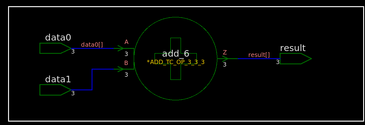
add without implicit sign
extension
unsigned
rtl
1 2 3 4 5 6 7
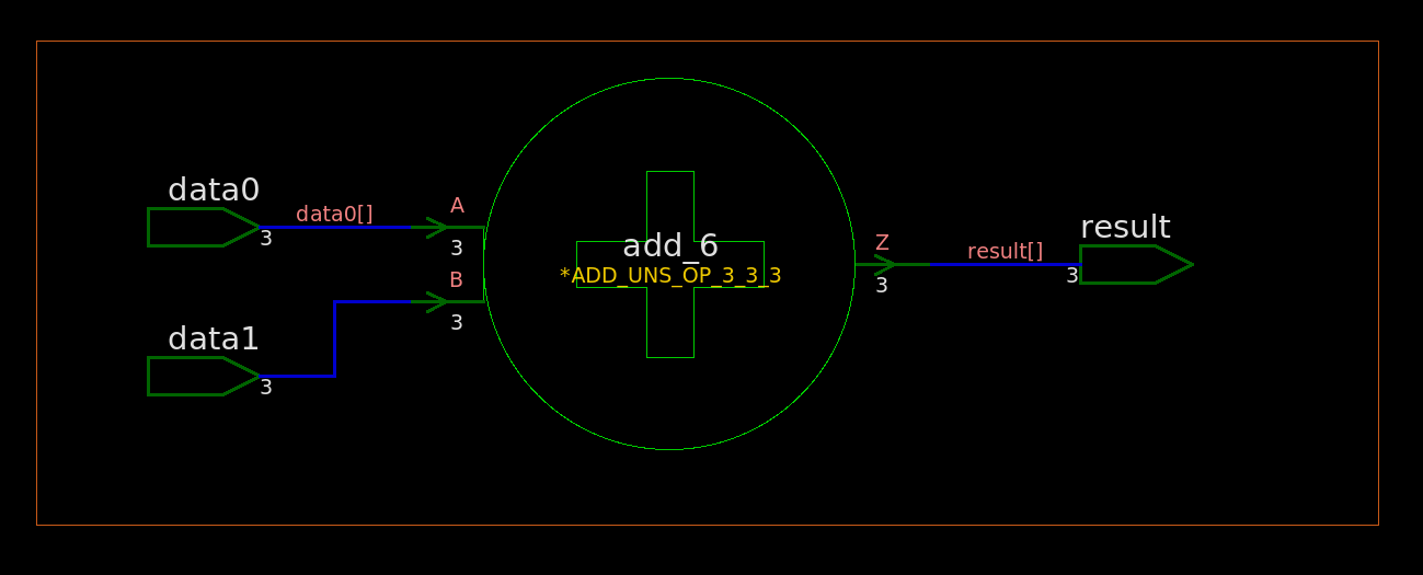
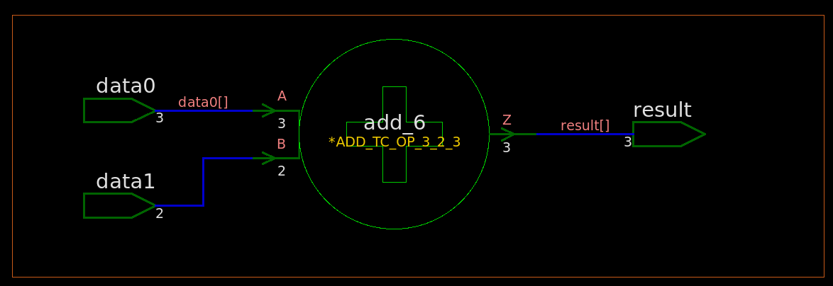
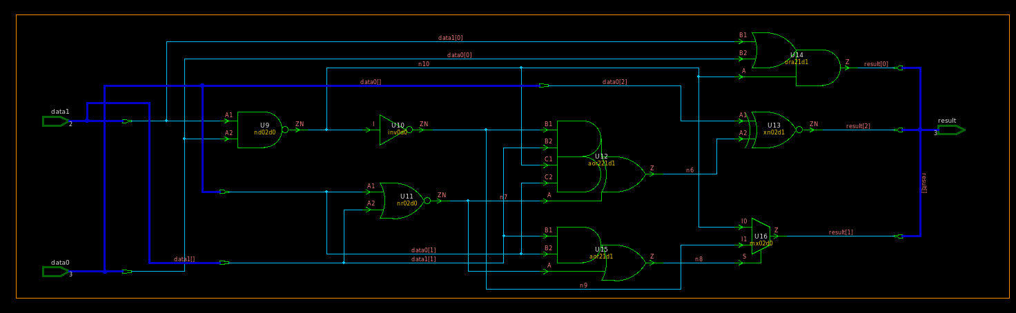
module TOP ( inputwire [2:0] data0 ,inputwire [2:0] data1 ,outputwire [2:0] result ); assign result = data0 + data1; endmodule
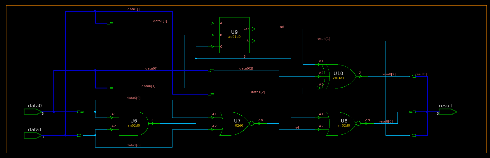
synthesized netlist
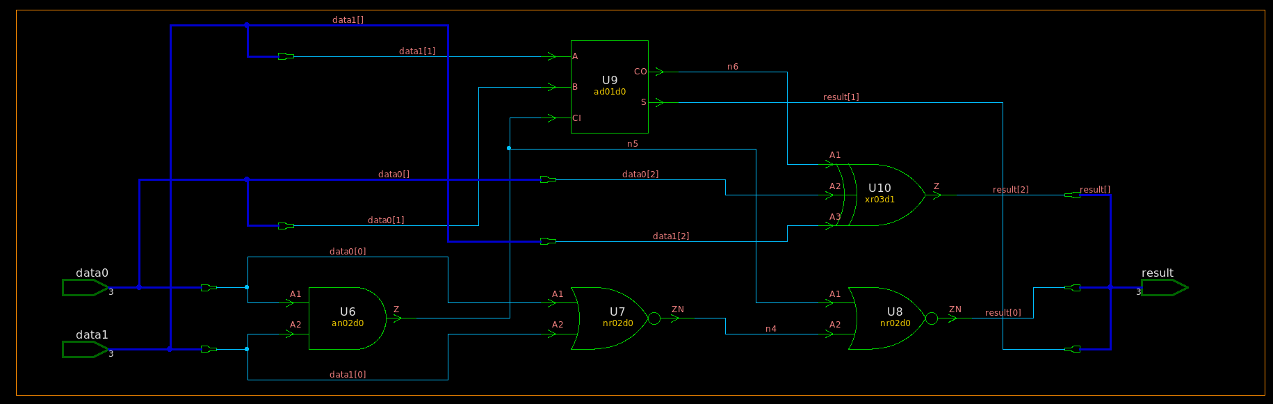
1 2 3 4 5 6 7 8 9 10 11 12 13 14 15 16 17 18 19
///////////////////////////////////////////////////////////// // Created by: Synopsys DC Ultra(TM) in wire load mode // Version : S-2021.06-SP5 // Date : Sat May 7 11:43:27 2022 /////////////////////////////////////////////////////////////
module TOP ( data0, data1, result ); input [2:0] data0; input [2:0] data1; output [2:0] result; wire n4, n5, n6;
module TOP ( inputwiresigned [2:0] data0 ,inputwiresigned [2:0] data1 ,outputwiresigned [2:0] result ); assign result = data0 + data1; endmodule
synthesized netlist
1 2 3 4 5 6 7 8 9 10 11 12 13 14 15 16 17 18 19
///////////////////////////////////////////////////////////// // Created by: Synopsys DC Ultra(TM) in wire load mode // Version : S-2021.06-SP5 // Date : Sat May 7 11:48:54 2022 /////////////////////////////////////////////////////////////
module TOP ( data0, data1, result ); input [2:0] data0; input [2:0] data1; output [2:0] result; wire n4, n5, n6;
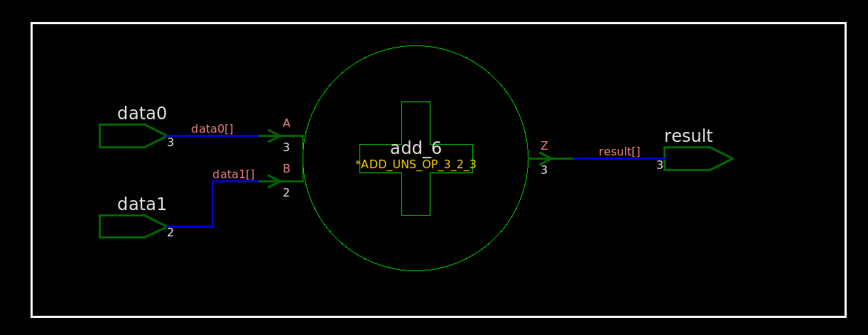
module TOP ( inputwire [2:0] data0 // 3 bit unsigned ,inputwire [1:0] data1 // 2 bit unsigned ,outputwire [2:0] result // 3 bit unsigned ); assign result = data0 + data1; endmodule
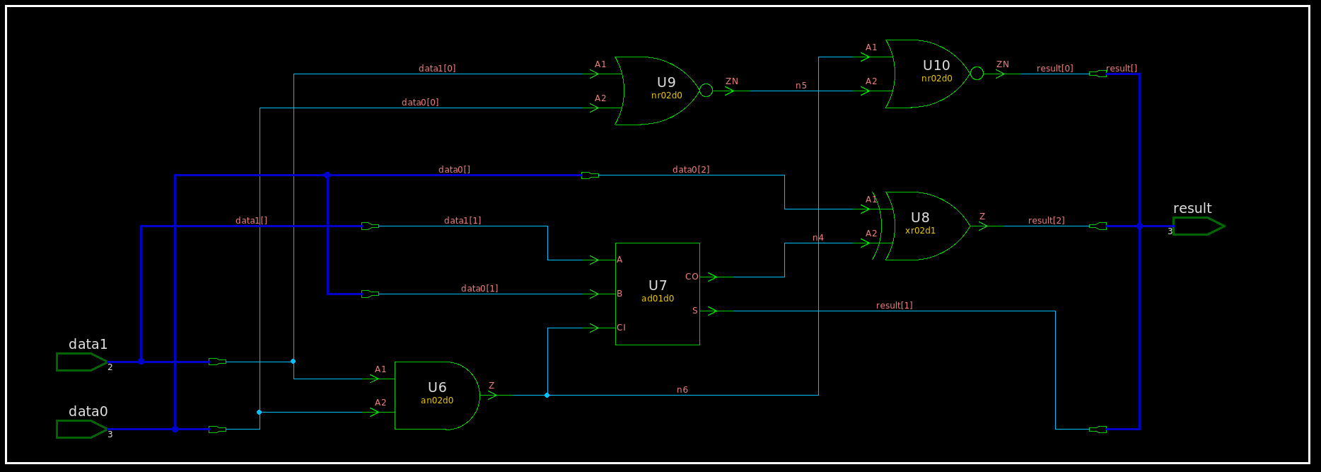
synthesized netlist
1 2 3 4 5 6 7 8 9 10 11 12 13 14 15 16 17 18 19
///////////////////////////////////////////////////////////// // Created by: Synopsys DC Ultra(TM) in wire load mode // Version : S-2021.06-SP5 // Date : Sat May 7 12:15:58 2022 /////////////////////////////////////////////////////////////
module TOP ( data0, data1, result ); input [2:0] data0; input [1:0] data1; output [2:0] result; wire n4, n5, n6;
///////////////////////////////////////////////////////////// // Created by: Synopsys DC Ultra(TM) in wire load mode // Version : S-2021.06-SP5 // Date : Sat May 7 12:21:51 2022 /////////////////////////////////////////////////////////////
UC Berkeley CS150 Lec #20: Finite State Machines [slides]
always@( * )
always@( * ) blocks are used to describe Combinational
Logic, or Logic Gates. Only = (blocking) assignments should
be used in an always@( * ) block.
Latch Inference
If you DON'T assign every element that can be
assigned inside an always@( * ) block every time that
always@( * ) block is executed, a latch will be inferred
for that element
The approaches to avoid latch generation:
set default values
proper use of the else statement, and other flow
constructs
without default values
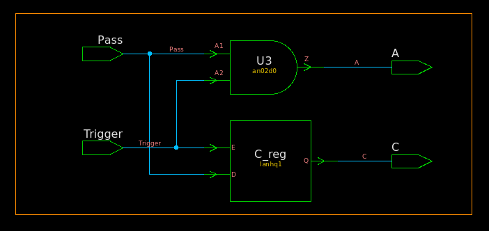
latch is generated
RTL
1 2 3 4 5 6 7 8 9 10 11 12 13 14
module TOP ( inputwire Trigger, inputwire Pass, outputreg A, outputreg C ); always @(*) begin A = 1'b0; if (Trigger) begin A = Pass; C = Pass; end end endmodule
synthesized netlist
1 2 3 4 5 6 7 8 9 10 11 12 13 14 15
///////////////////////////////////////////////////////////// // Created by: Synopsys DC Ultra(TM) in wire load mode // Version : S-2021.06-SP5 // Date : Mon May 9 17:09:18 2022 /////////////////////////////////////////////////////////////
module TOP ( Trigger, Pass, A, C ); input Trigger, Pass; output A, C;
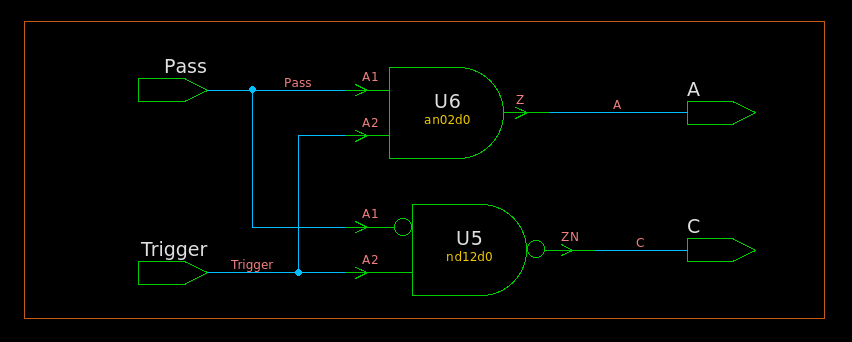
Default values are an easy way to avoid latch generation
RTL
1 2 3 4 5 6 7 8 9 10 11 12 13 14
module TOP ( inputwire Trigger, inputwire Pass, outputreg A, outputreg C ); always @(*) begin A = 1'b0; C = 1'b1; if (Trigger) begin A = Pass; C = Pass; end end
synthesized netlist
1 2 3 4 5 6 7 8 9 10 11 12 13 14 15 16
///////////////////////////////////////////////////////////// // Created by: Synopsys DC Ultra(TM) in wire load mode // Version : S-2021.06-SP5 // Date : Mon May 9 17:12:47 2022 /////////////////////////////////////////////////////////////
module TOP ( Trigger, Pass, A, C ); input Trigger, Pass; output A, C;
regsigned [8:0] t; // extend 1b begin if(plus) begin t = {a[7], a} + {1'b0, b}; satop_sus8b = (t[8:7]==2'b01) ? {1'b0, {7{1'b1}}} // up saturate for signed : t[7:0]; endelsebegin t = {a[7], a} - {1'b0, b}; satop_sus8b = (t[8:7]==2'b10) ? {1'b1, {7{1'b0}}} // dn saturate for signed : t[7:0]; end end endfunction
A power spectrum is equal to the square of the absolute value of
DFT.
The sum of all power spectral lines in a power spectrum is equal to
the power of the input signal.
The integral of a PSD is equal to the power of the input
signal.
power spectrum has units of \(V^2\)
and power spectral density has units of \(V^2/Hz\)
Parseval's theorem is a property of the Discrete
Fourier Transform (DFT) that states: \[
\sum_{n=0}^{N-1}|x(n)|^2 = \frac{1}{N}\sum_{k=0}^{N-1}|X(k)|^2
\] Multiply both sides of the above by \(1/N\): \[
\frac{1}{N}\sum_{n=0}^{N-1}|x(n)|^2 =
\frac{1}{N^2}\sum_{k=0}^{N-1}|X(k)|^2
\]\(|x(n)|^2\) is instantaneous
power of a sample of the time signal. So the left side of the equation
is just the average power of the signal over the N
samples. \[
P_{\text{av}} = \frac{1}{N^2}\sum_{k=0}^{N-1}|X(k)|^2\text{, }V^2
\] For the each DFT bin, we can say: \[
P_{\text{bin}}(k) = \frac{1}{N^2}|X(k)|^2\text{,
k=0:N-1, }V^2/\text{bin}
\] This is the power spectrum of the signal.
Note that \(X(k)\) is the
two-sided spectrum. If \(x(n)\) is real, then \(X(k)\) is symmetric about \(fs/2\), with each side containing half of
the power. In that case, we can choose to keep just the
one-sided spectrum, and multiply Pbin by 2
(except DC & Nyquist):
rng default Fs = 1000; t = 0:1/Fs:1-1/Fs; x = cos(2*pi*100*t) + randn(size(t)); N = length(x); xdft = fft(x); xsq_sum_avg = sum(x.^2)/N; specsq_sum_avg = sum(abs(xdft).^2)/N^2;
where xsq_sum_avg is same with
specsq_sum_avg
For a discrete-time sequence x(n), the DFT is defined as: \[
X(k) = \sum_{n=0}^{N-1}x(n)e^{-j2\pi kn/N}
\] By it definition, the DFT does NOT apply to
infinite duration signals.
Different scaling is needed to apply for amplitude spectrum, power
spectrum and power spectrum density, which shown as below
\(f_s\) in Eq.(13) is sample
rate rather than frequency resolution.
And Eq.(13) can be expressed as \[
\text{PSD}(k) =\frac{1}{f_{\text{res}}\cdot
N\sum_{n}w^2(n)}\left|X_{\omega}(k)\right|^2
\] where \(f_{\text{res}}\) is
frequency resolution
We define the following two sums for normalization purposes:
where Normalized Equivalent Noise BandWidth is
defined as \[
\text{NENBW} =\frac{N S_2}{S_1^2}
\] and Effective Noise BandWidth is \[
\text{ENBW} =f_{\text{res}} \cdot \frac{N S_2}{S_1^2}
\]
For Rectangular window, \(\text{ENBW}
=f_{\text{res}}\)
This equivalent noise bandwidth is required when the
resulting spectrum is to be expressed as spectral density (such as
for noise measurements).
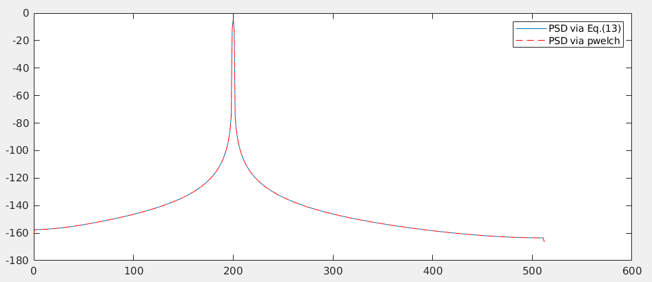
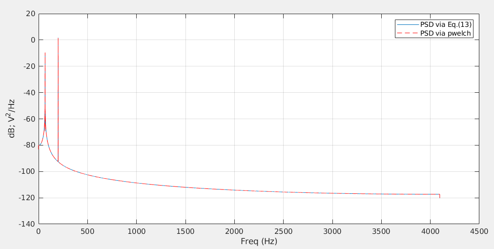
plot(Fx1,10*log10(Pxx1),Fx2,10*log10(Pxx2),'r--'); legend('PSD via Eq.(13)','PSD via pwelch')
window effects
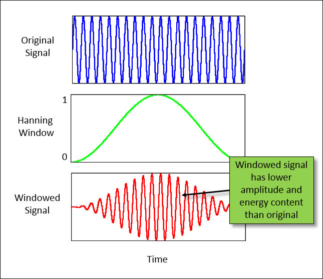
It is possible to correct both the amplitude and energy content of
the windowed signal to equal the original signal. However, both
corrections cannot be applied simultaneously
power spectral density (PSD)\[
\text{PSD} =\frac{\left|X_{\omega}(k)\right|^2}{f_s\cdot S_2}
\]
We have \(\text{PSD} =
\frac{\text{PS}}{\text{ENBW}}\), where \(\text{ENBW}=\frac{N \cdot
S_2}{S_1^2}f_{\text{res}}\)
linear power spectrum\[
\text{PS}_L=\frac{|X_{\omega}(k)|^2}{N\cdot S_2}
\]
usage: RMS value, total power \[
\text{PS}_L(k)=\text{PSD(k)} \cdot f_{\text{res}}
\]
Window Correction Factors
While a window helps reduce leakage (The window reduces the jumps at
the ends of the repeated signal), the window itself distorts the data in
two different ways:
Amplitude – The amplitude of the signal
is reduced
This is due to the fact that the window removes information in the
signal
Energy – The area under the curve, or
energy of the signal, is reduced
Window correction factors are used to try and
compensate for the effects of applying a window to data. There are both
amplitude and energy correction factors.
Window Type
Amplitude Correction (\(K_a\))
Energy Correction (\(K_e\))
Rectangluar
1.0
1.0
hann
1.9922
1.6298
blackman
2.3903
1.8155
kaiser
1.0206
1.0204
Only the Uniform window (rectangular window), which is equivalent to
no window, has the same amplitude and energy correction factors.
In literature, Coherent power gain is defined show
below, which is close related to \(K_a\)\[
\text{Coherent power gain (dB)} = 20 \; log_{10} \left( \frac{\sum_n
w[n]}{N} \right)
\]
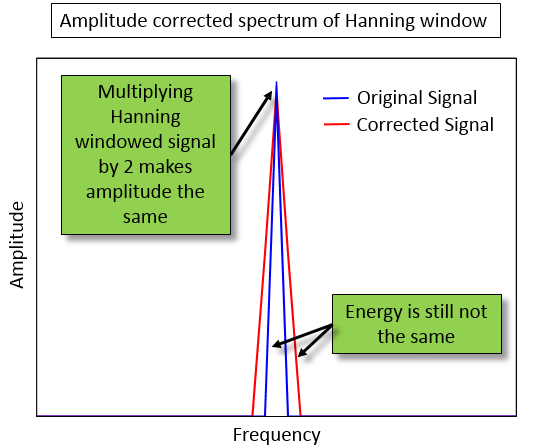
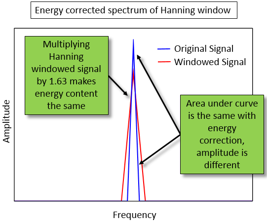
With amplitude correction, by multiplying by two, the peak
value of both the original and corrected spectrum match. However
the energy content is not the same.
The amplitude corrected signal (red) appears to have more energy, or
area under the curve, than the original signal (blue).
Multiplying the values in the spectrum by 1.63, rather than 2, makes
the area under the curve the same for both the original signal
(blue) and energy corrected signal (red)
hanning's correction factors:
1 2 3 4
N = 256; w = hanning(N); Ka = N/sum(w) Ke = sqrt(N/sum(w.^2))
%% plot psd of two methods plot(Fx1,10*log10(Pxx1),Fx2,10*log10(Pxx2),'r--'); legend('PSD via Eq.(13)','PSD via pwelch') grid on; xlabel('Freq (Hz)'); ylabel('dB; V^2/Hz')
We may also want to know for example the RMS value of the signal, in
order to know how much power the signal generates. This can be done
using Parseval’s theorem.
For a periodic signal, which has a discrete
spectrum, we obtain its total RMS value by summing the included signals
using \[
x_{\text{rms}}=\sqrt{\sum R_{xk}^2}
\] Where \(R_{xk}\) is the RMS
value of each sinusoid for \(k=1,2,3,...\) The RMS value of a signal
consisting of a number of sinusoids is consequently equal to the
square root of the sum of the RMS values.
This result could also be explained by noting that sinusoids of
different frequencies are orthogonal, and can therefore
be summed like vectors (using Pythagoras’ theorem)
For a random signal we cannot interpret the spectrum in the same way.
As we have stated earlier, the PSD of a random signal contains all
frequencies in a particular frequency band, which makes it
impossible to add the frequencies up. Instead, as the PSD is a
density function, the correct interpretation is to sum the area under
the PSD in a specific frequency range, which then is the square of the
RMS, i.e., the mean-square value of the signal \[
x_{\text{rms}}=\sqrt{\int G_{xx}(f)df}=\sqrt{\text{area under the
curve}}
\] The linear spectrum, or RMS
spectrum, defined by \[\begin{align}
X_L(k) &= \sqrt{\text{PSD(k)} \cdot f_{\text{res}}}\\
&=\sqrt{\frac{\left|X_{\omega}(k)\right|^2}{f_{\text{res}}\cdot
N\sum_{n}\omega^2(n)} \cdot f_{\text{res}}} \\
&= \sqrt{\frac{\left|X_{\omega}(k)\right|^2}{N\sum_{n}\omega^2(n)}}
\\
&= \sqrt{\frac{|X_{\omega}(k)|^2}{N\cdot S_2}}
\end{align}\]
The corresponding linear power spectrum or
RMS power spectrum can be defined by \[\begin{align}
\text{PS}_L(k)&=X_L(k)^2=\frac{|X_{\omega}(k)|^2}{S_1^2}\frac{S_1^2}{N\cdot
S_2} \\
&=\text{PS}(k) \cdot \frac{S_1^2}{N\cdot S_2}
\end{align}\]
So, RMS can be calculated as below \[\begin{align}
P_{\text{tot}} &= \sum \text{PS}_L(k) \\
\text{RMS} &= \sqrt{P_{\text{tot}}}
\end{align}\]
DFT averaging
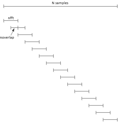
we use \(N= 8*\text{nfft}\) time
samples of \(x\) and set the number of
overlapping samples to \(\text{nfft}/2 =
512\). pwelch takes the DFT of \(\text{Navg} = 15\) overlapping segments of
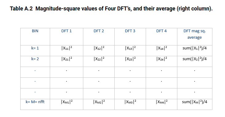
\(x\), each of length \(\text{nfft}\), then averages the \(|X(k)|^2\) of the DFT’s.
In general, if there are an integer number of segments that cover all
samples of N, we have \[
N = (N_{\text{avg}}-1)*D + \text{nfft}
\] where \(D=\text{nfft}-\text{noverlap}\). For our
case, with \(D = \text{nfft}/2\) and
\(N/\text{nfft} = 8\), we have \[
N_{\text{avg}}=2*N/\text{nfft}-1=15
\] For a given number of time samples N, using overlapping
segments lets us increase \(N_{avg}\)
compared with no overlapping. In this case, overlapping of 50% increases
\(N_{avg}\) from 8 to 15. Here is the
Matlab code to compute the spectrum:
1 2 3 4 5 6 7 8
nfft= 1024; N= nfft*8; % number of samples in signal n= 0:N-1; x= A*sin(2*pi*f0*n*Ts) + .1*randn(1,N); % 1 W sinewave + noise noverlap= nfft/2; % number of overlapping time samples window= hanning(nfft); [pxx,f]= pwelch(x,window,noverlap,nfft,fs); % W/Hz PSD PdB_bin= 10*log10(pxx*fs/nfft); % dBW/bin
DFT averaging reduces the variance \(\sigma^2\) of the noise spectrum by a
factor of \(N_{avg}\), as long as
noverlap is not greater than nfft/2
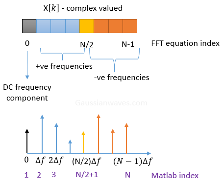
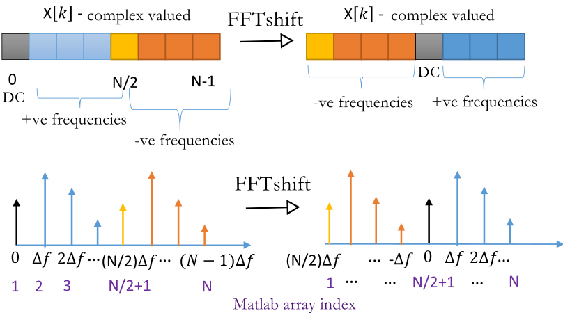
fftshift
The result of fft and its index is shown as below
After fftshift
1 2 3 4 5
>> fftshift([01234567])
ans =
45670123
1 2 3 4 5 6 7 8 9
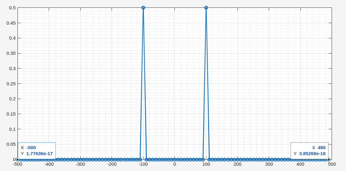
clear; N = 100; fs = 1000; fx = 100; x = cos(2*pi*fx/fs*[0:1:N-1]); s = abs(fftshift(fft(x)))/N; fx = linspace(0,N-1,N)*fs/N -fs/2; plot(fx, s, 'o-', 'linewidth', 2); grid on; grid minor;
dft and
psd function in virtuoso
dft always return
To compensate windowing effect, \(W(n)\), the dft output should
be multiplied by \(K_a\), e.g. 1.9922
for hanning window.
psd function has taken into account \(K_e\), postprocessing is
not needed
reference
Heinzel, Gerhard, A. O. Rüdiger and Roland Schilling. "Spectrum and
spectral density estimation by the Discrete Fourier transform (DFT),
including a comprehensive list of window functions and some new at-top
windows." (2002). URL: https://holometer.fnal.gov/GH_FFT.pdf
Rapuano, Sergio, and Harris, Fred J., An Introduction to FFT and Time
Domain Windows, IEEE Instrumentation and Measurement Magazine, December,
2007. https://ieeexplore.ieee.org/document/4428580
Jens Ahrens, Carl Andersson, Patrik Höstmad, Wolfgang Kropp,
“Tutorial on Scaling of the Discrete Fourier Transform and the Implied
Physical Units of the Spectra of Time-Discrete Signals” in 148th
Convention of the AES, e-Brief 56, May 2020 [ pdf,
web
].
Manolakis, D., & Ingle, V. (2011). Applied Digital Signal
Processing: Theory and Practice. Cambridge: Cambridge University
Press. doi:10.1017/CBO9780511835261
a generalization of the continuous-time Fourier
transform
converts integro-differential equations into algebraic
equations
z-transforms
a generalization of the discrete-time Fourier
transform
converts difference equations into algebraic
equations
system function,transfer function: \(H(s)\)
frequency response: \(H(j\omega)\), if the ROC of \(H(s)\) includes the imaginary axis,
i.e.\(s=j\omega \in \text{ROC}\)
Laplace Transform
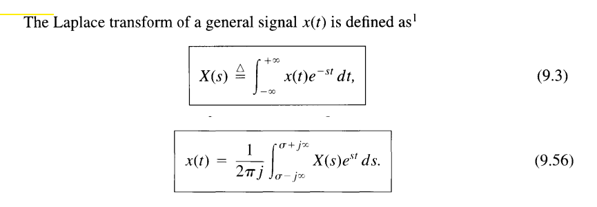
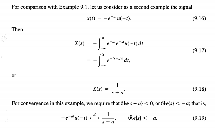
To specify the Laplace transform of a signal, both the
algebraic expression and the ROC are
required. The ROC is the range of values of \(s\) for the integral of \(t\) converges
bilateral Laplace transform
where \(s\) in the ROC and \(\mathfrak{Re}\{s\}=\sigma\)
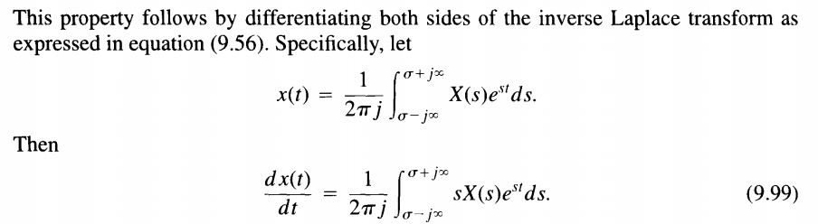
The formal evaluation of the integral for a general \(X(s)\) requires the use of contour
integration in the complex plane. However, for the class of
rational transforms, the inverse Laplace transform can be
determined without directly evaluating eq. (9.56) by using the technique
of partial fraction expansion
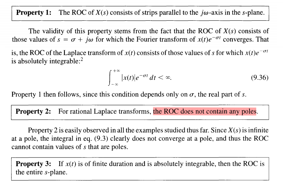
ROC Property
The range of values of s for which the integral in converges is
referred to as the region of convergence (which we
abbreviate as ROC) of the Laplace transform
i.e. no pole in RHP for stable LTI sytem
System Causality
For a causal LTI system, the impulse response is zero for \(t \lt 0\) and thus is right
sided
causality implies that the ROC is to the right of the rightmost pole,
but the converse is not in general true, unless the system function is
rational
System Stability
The system is stable, or equivalently, that \(h(t)\) is absolutely
integrable and therefore has a Fourier transform, then the ROC
must include the entire \(j\omega\)-axis
all of the poles have negative real
parts
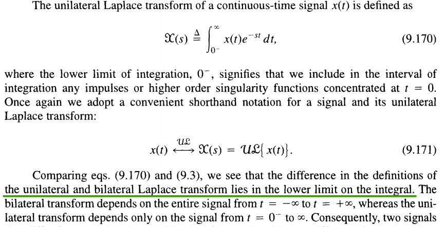
Unilateral Laplace transform
analyzing causal systems and, particularly,
systems specified by linear constant-coefficient differential equations
with nonzero initial conditions (i.e., systems
that are not initially at rest)
A particularly important difference between the properties of the
unilateral and bilateral transforms is the differentiation
property\(\frac{\mathrm{d}}{\mathrm{d}t}x(t)\)
Laplace Transform
Bilateral Laplace Transform
\(sX(s)\)
Unilateral Laplace Transform
\(sX(s)-x(0^-)\)
Integration by parts for unilateral Laplace transform
in Bilateral Laplace Transform
In fact, the initial- and final-value
theorems are basically unilateral transform
properties, as they apply only to signals \(x(t)\) that are identically \(0\) for \(t \lt
0\).
\(z\)-Transform
The \(z\)-transform for
discrete-time signals is the counterpart of the Laplace transform for
continuous-time signals
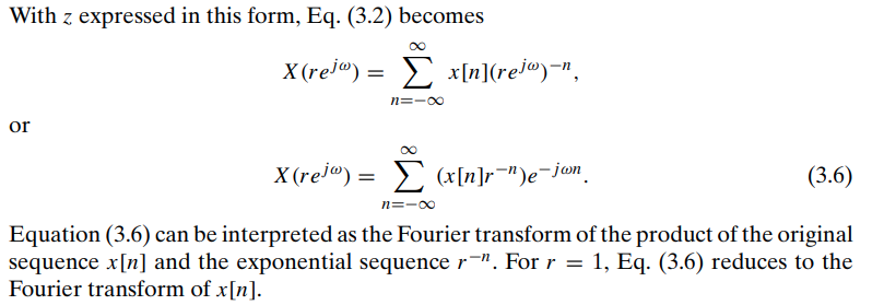
where \(z=re^{j\omega}\)
The \(z\)-transform evaluated on the
unit circle corresponds to the Fourier transform
ROC Property
system stability
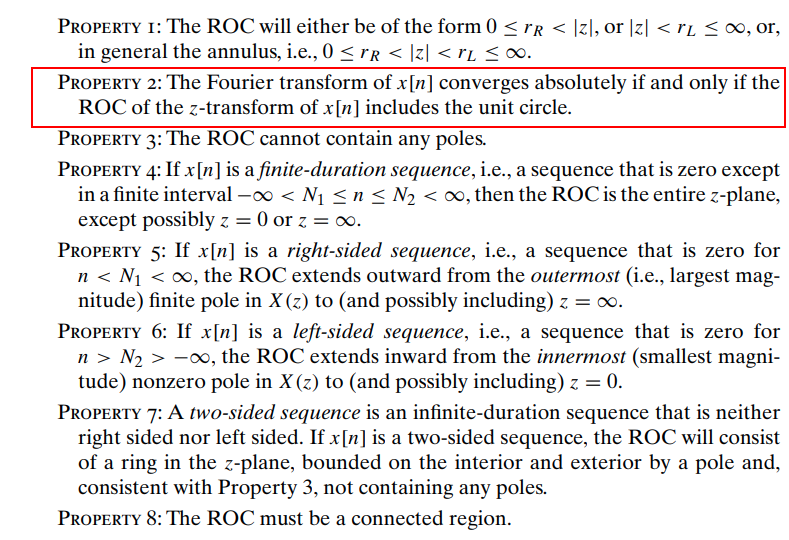
The system is stable, or equivalently, that \(h[n]\) is absolutely
summable and therefore has a Fourier transform, then the ROC
must include the unit circle
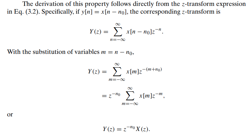
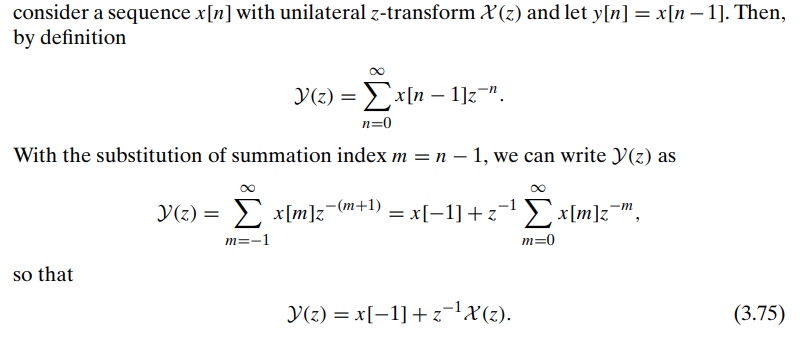
The time shifting property is different in the
unilateral case because the lower limit in the unilateral transform
definition is fixed at zero, \(x[n-n_0]\)
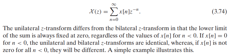
bilateral \(z\)-transform
unilateral \(z\)-transform
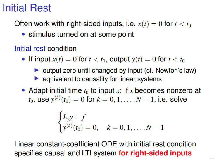
Initial rest condition
Initial Value Theorem
& Final Value Theorem
Laplace Transform
Two valuable Laplace transform theorem
Initial Value Theorem, which states that it is always possible to
determine the initial value of the time function \(f(t)\) from its Laplace transform \[
\lim _{s\to \infty}sF(s) = f(0^+)
\]
Final Value Theorem allows us to compute the constant
steady-state value of a time function given its Laplace
transform \[
\lim _{s\to 0}sF(s) = f(\infty)
\]
If \(f(t)\) is step response, then
\(f(0^+) = H(\infty)\) and \(f(\infty) = H(0)\), where \(H(s)\) is transfer function
\(z\)-transform
Initial Value Theorem \[
f[0]=\lim_{z\to\infty}F(z)
\] final value theorem \[
\lim_{n\to\infty}f[n]=\lim_{z\to1}(z-1)F(z)
\]
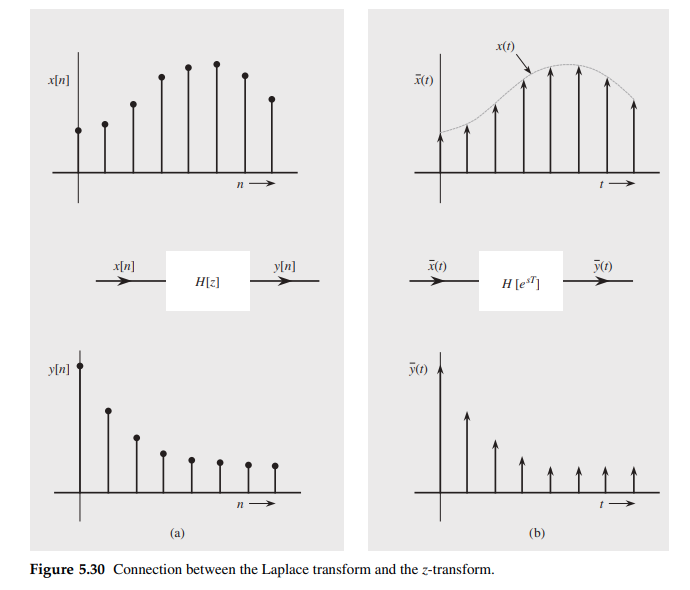
discrete-time systems also can be analyzed by means of the Laplace
transform — the \(z\)-transform is the
Laplace transform in disguise and that discrete-time systems can be
analyzed as if they were continuous-time systems.
A continuous-time system with transfer function \(H(s)\) that is identical in
structure to the discrete-time system \(H[z]\) except that the
delays in \(H[z]\) are
replaced by elements that delay continuous-time
signals
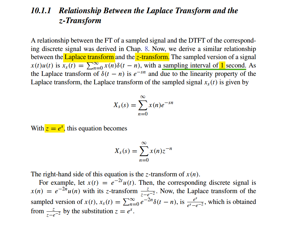
The \(z\)-transform of a
sequence can be considered to be the Laplace transform of
impulses sampled train with a change of variable \(z = e^{sT}\) or \(s = \frac{1}{T}\ln z\)
Note that the transformation \(z =
e^{sT}\) transforms the imaginary axis in the \(s\) plane (\(s =
j\omega\)) into a unit circle in the \(z\) plane (\(z =
e^{sT} = e^{j\omega T}\), or \(|z| =
1\))
Note: \(\bar{h}(t)\) is the impulse
sampled version of \(h(t)\)
Note \(\bar{h}(t)\) is impulse
sampled signal, whose CTFT is scaled by \(\frac{1}{T}\) of continuous signal \(h(t)\), \(\overline{H}[e^{sT}]=\overline{H}(e^{sT})\)
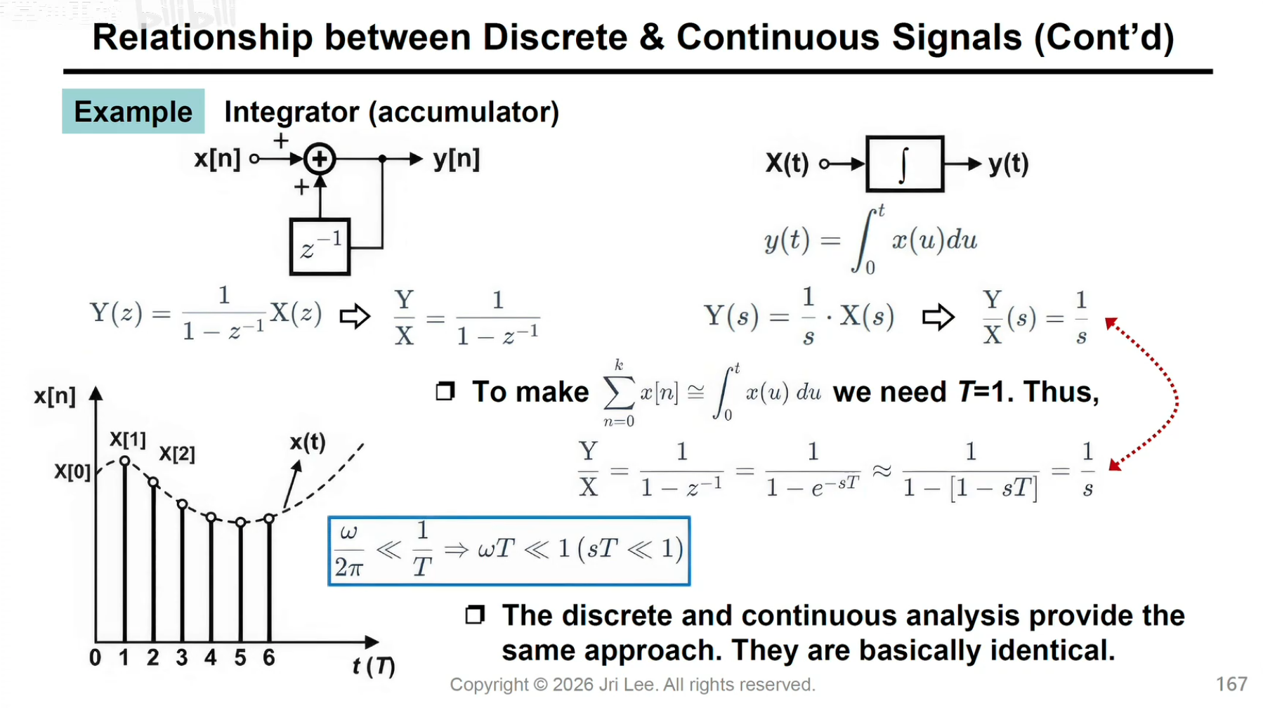
is the approximation of continuous time system response, for example
summation \(\frac{1}{1-z^{-1}}\)\[
\frac{1}{1-z^{-1}} = \frac{1}{1-e^{-sT}} \approx \frac{1}{j\omega \cdot
T}
\] And we know transform of integral \(u(t)\) is \(\frac{1}{s}\), as expected there is ratio
\(T\)
Staszewski, Robert Bogdan, and Poras T. Balsara. All-digital
frequency synthesizer in deep-submicron CMOS. John Wiley &
Sons, 2006
D. Sundararajan. Signals and Systems A Practical Approach Second
Edition, 2023
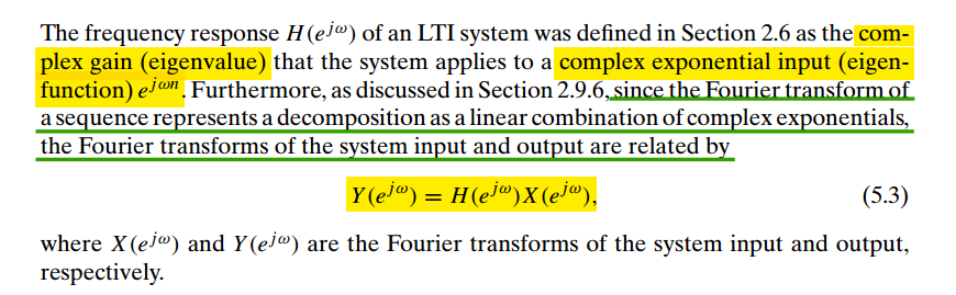
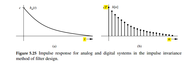
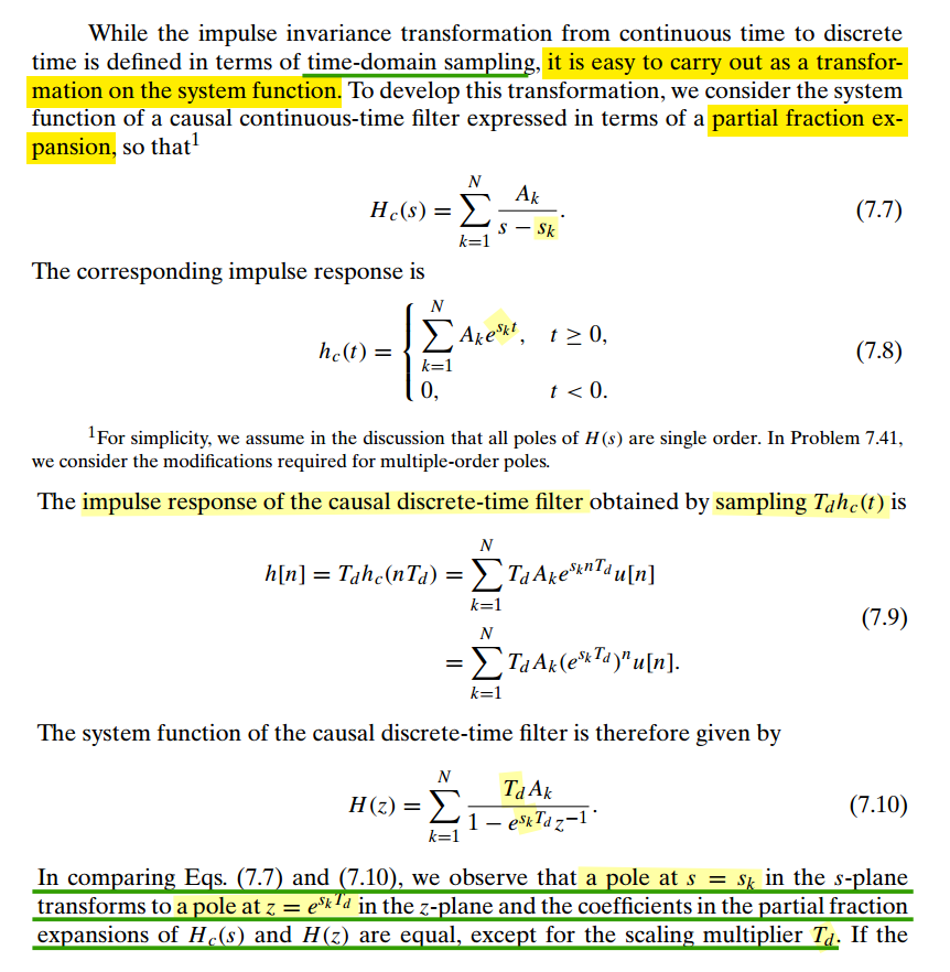
When \(h[n]\) and \(h_c(t)\) are related through the above
equation, i.e., the impulse response of the discrete-time system is a
scaled, sampled version of \(h_c(t)\), the discrete-time system
is said to be an impulse-invariant version of the continuous-time
system
we have \[
H(e^{j\hat{\omega}}) =
H_c\left(j\frac{\hat{\omega}}{T}\right),\space\space |\hat{\omega}| \lt
\pi
\]
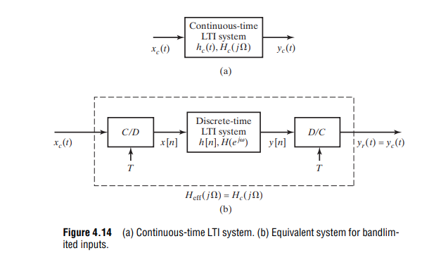
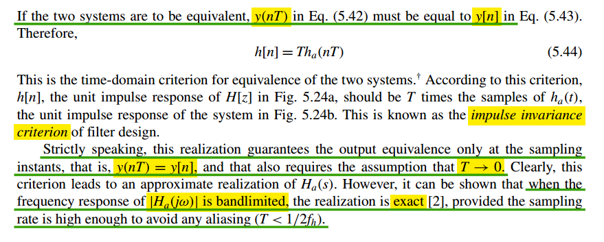
\(h[n] = Th_c(nT)\) and \(T\to 0\)
guarantees \(y_c(nT) = y_r(nT)\),
i.e. output equivalenceonly at the sampling
instants
\(H_c(j\Omega)\) is
bandlimited and \(T \lt
1/2f_h\)
guarantees \(y_c(t) =
y_r(t)\)
The scaling of \(T\) can
alternatively be thought of as a normalization of the time domain, that
is average impulse response shall be same i.e., \(h[n]\times 1 = h(nT)\times T\)
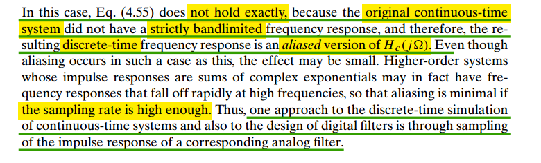
note that the impulse-invariant transform is
not appropriate for high-pass
responses, because of aliasing
errors
⭐ bandlimited
⭐ bandlimited
Scale the Result if impulse not multiplied with
\(T_s\)
t = linspace(0, 10); dt = t(2) - t(1); %u = @(t) heaviside(t); % by default, heavside(0) = 1/2, but at t = 0, we should have u(0) = 1 by definition of unit step u = @(t) (t>=0); Vin = @(t) u(t)-u(t-3); h = @(t) ( exp(-2*t)/6 ) + ( 3/16*exp(-t) ) - ( exp(-5*t)/48 ); y = conv(Vin(t), h(t))*dt; % must scale by dt plot(t,y(1:numel(t)),'-x') legend('wt - Laplace','wt - convolution integral','wt - convolution sum')
continuous-time filter designs to discrete-time designs through
techniques such as impulse invariance
useful functions
using fft
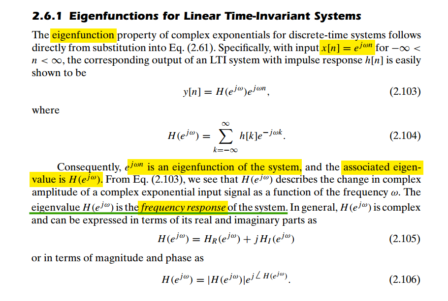
The outputs of the DFT are samples of the DTFT
using freqz
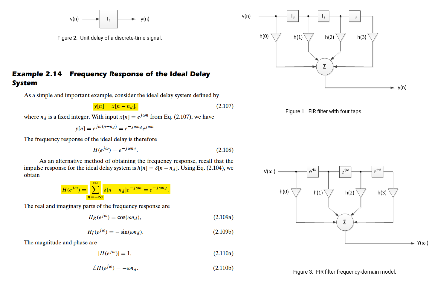
modeling as FIR filter, and the impulse response sequence of an FIR
filter is the same as the sequence of filter coefficients, we can
express the frequency response in terms of either the filter
coefficients or the impulse response
fft is used in freqz internally
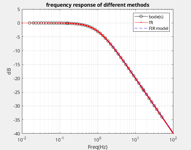
freqz method is straightforward, which apply impulse
invariance criteria. Though fft is used for signal
processing mostly,
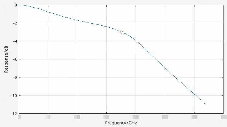
%% continuous system s = tf('s'); h = 2*pi/(2*pi+s); % First order lowpass filter with 3-dB frequency 1Hz [mag, phs, wout] = bode(h); fct = wout(:)/2/pi; Hct_dB = 20*log10(mag(:));
Convolution Property of the Fourier Transform \[
x(t)*h(t)\longleftrightarrow X(\omega)H(\omega)
\] pulse response can be obtained by convolve impulse response
with UI length rectangular \[
H(\omega) = \frac{Y_{\text{pulse}}(\omega)}{X_{\text{rect}}(\omega)} =
\frac{Y_{\text{pulse}}(\omega)}{\text{sinc}(\omega)}
\]
1 2 3 4 5 6 7 8 9 10 11 12 13 14 15 16
% Convolution Property of the Fourier Transform % pulse(t) = h(t) * rect(t) % -> fourier transform % PULSE = H * RECT % FT(RECT) = sinc % H = PULSE/RECT = PULSE/sinc xx = pi*ui.*w(1:plt_num); y_sinc = ui.*sin(xx)./xx; y_sinc(1) = y_sinc(2); y_sinc = y_sinc/y_sinc(1); % we dont care the absoulte gain h_ban1 = abs(h(1:plt_num))./abs(y_sinc);
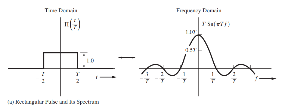
Notice that the complete definition of \(\operatorname{sinc}\) on \(\mathbb R\) is \[
\operatorname{Sa}(x)=\operatorname{sinc}(x) = \begin{cases} \frac{\sin
x}{x} & x\ne 0, \\ 1, & x = 0, \end{cases}
\] which is continuous.
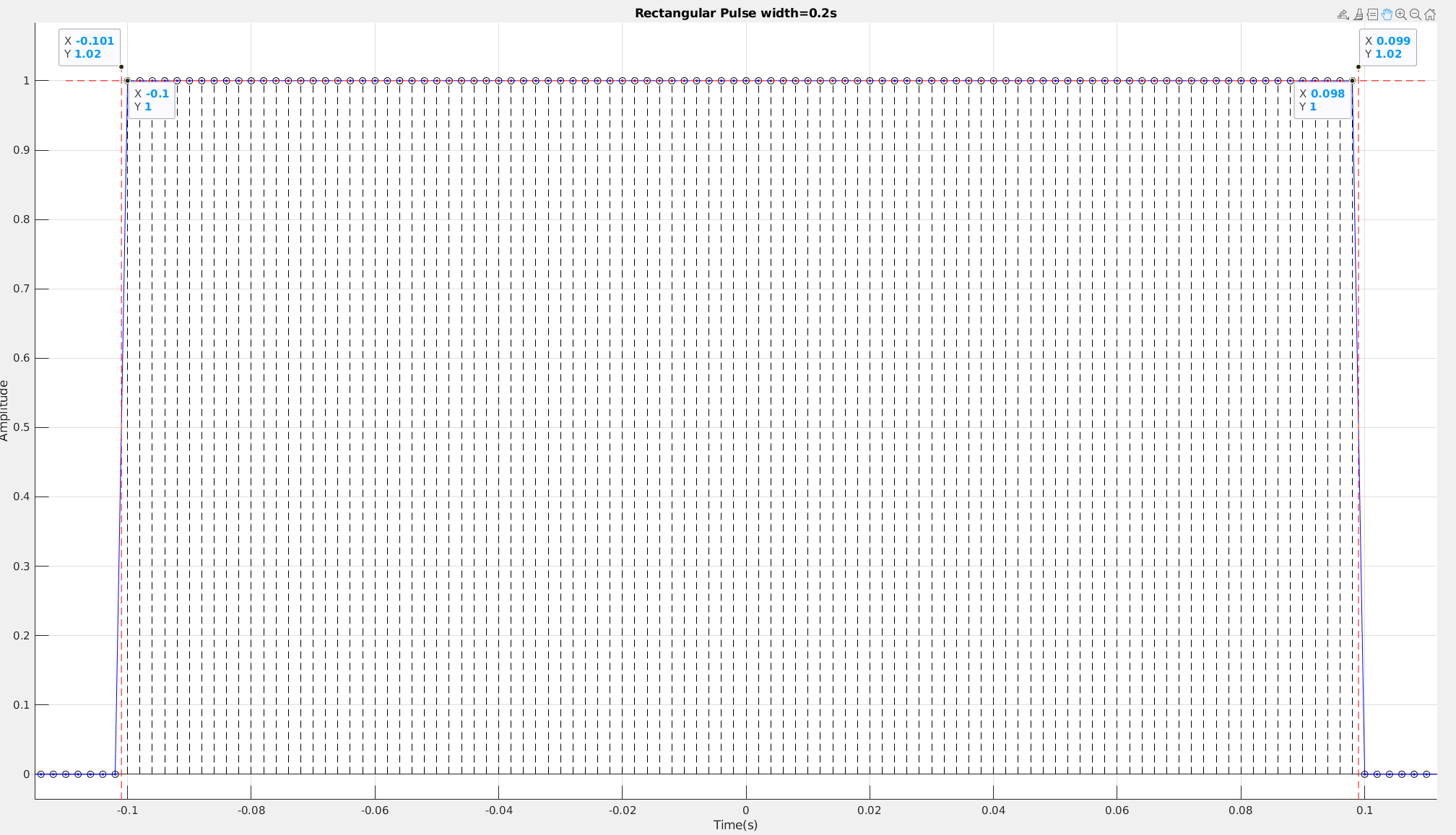
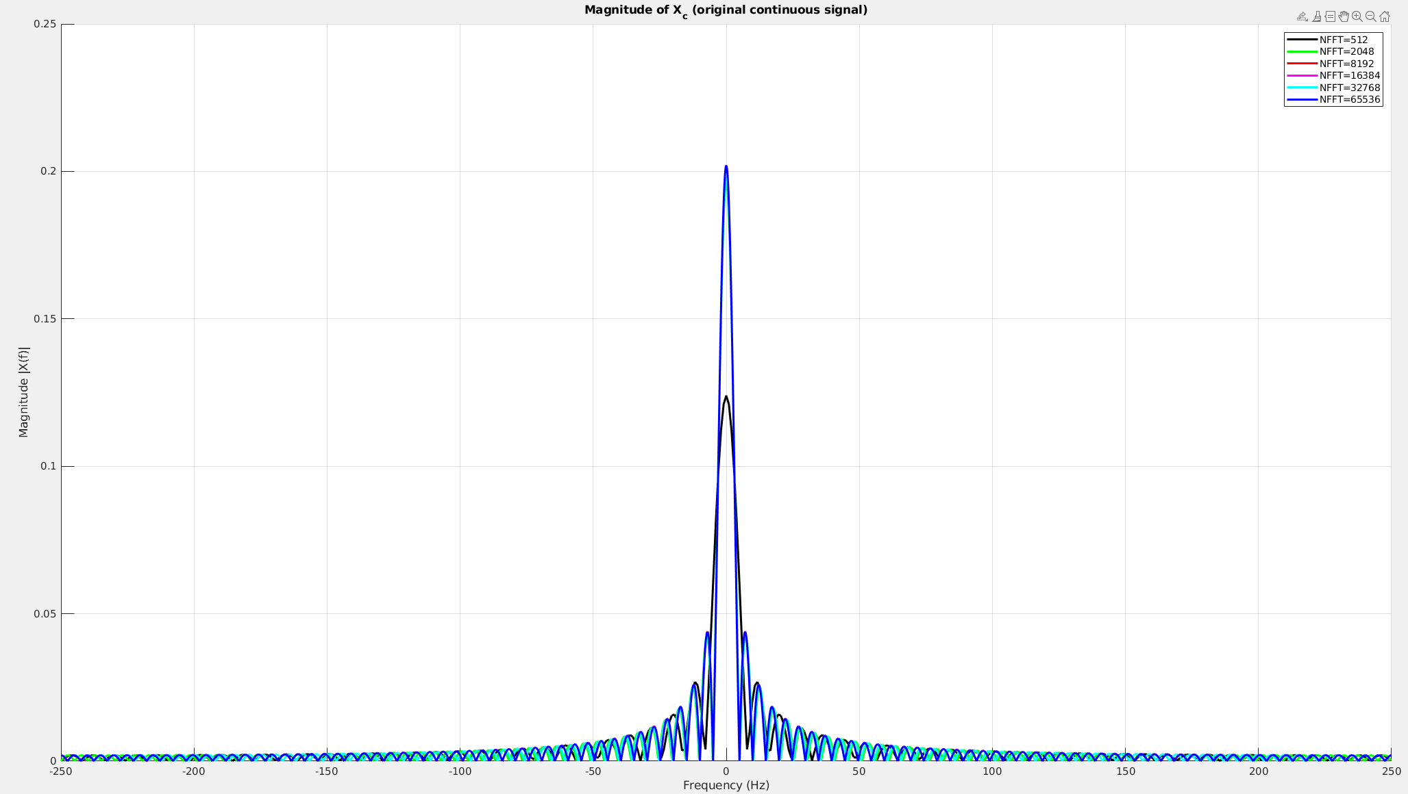
To approach to real spectrum of continuous rectangular waveform,
\(\text{NFFT}\) has to be big
enough.
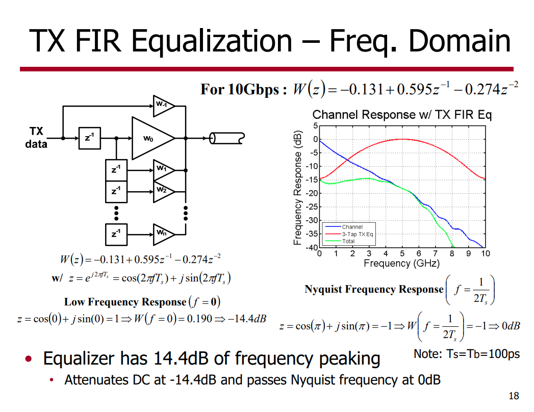
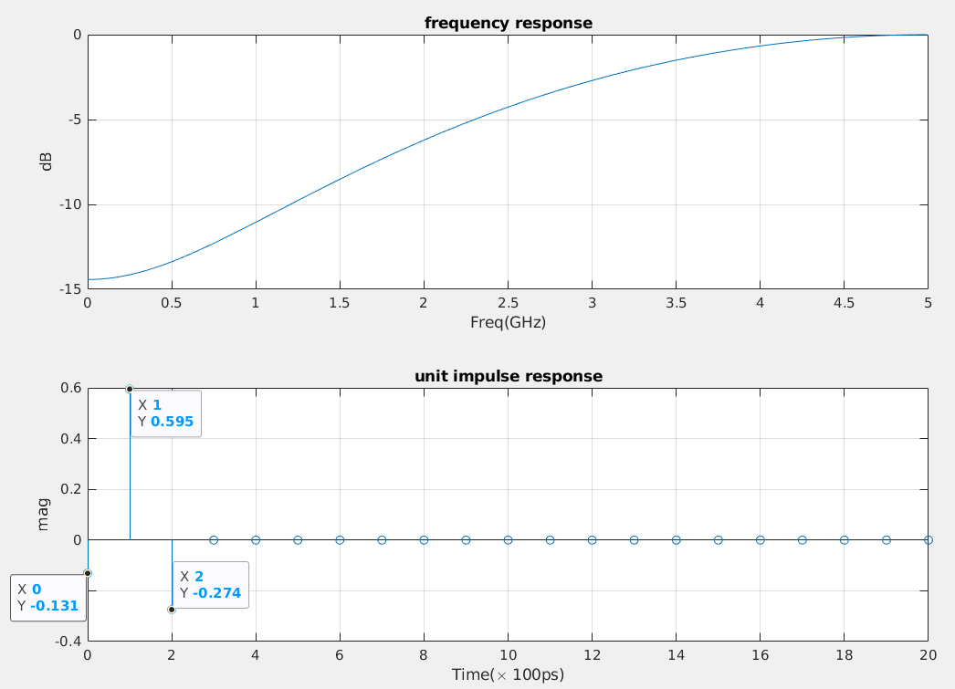
%% unit impulse response from transfer function subplot(2, 1, 2) z = tf('z', Ts); h = -0.131 + 0.595*z^(-1) -0.274*z^(-2); [y, t] = impulse(h); stem(t*1e10, y*Ts); % !!! y*Ts is essential grid on; title("unit impulse response"); xlabel('Time(\times 100ps)'); ylabel('mag');
impulse:
For discrete-time systems, the impulse response is the response to a
unit area pulse of length Ts and height 1/Ts,
where Ts is the sample time of the system. (This pulse
approaches \(\delta(t)\) as
Ts approaches zero.)
Scale output:
Multiply impulse output with sample period
Ts in order to correct 1/Ts height of
impulse function.
PSD transformation
If we have power spectrum or power spectrum density of both edge's
absolute jitter (\(x(n)\)) , \(P_{\text{xx}}\)
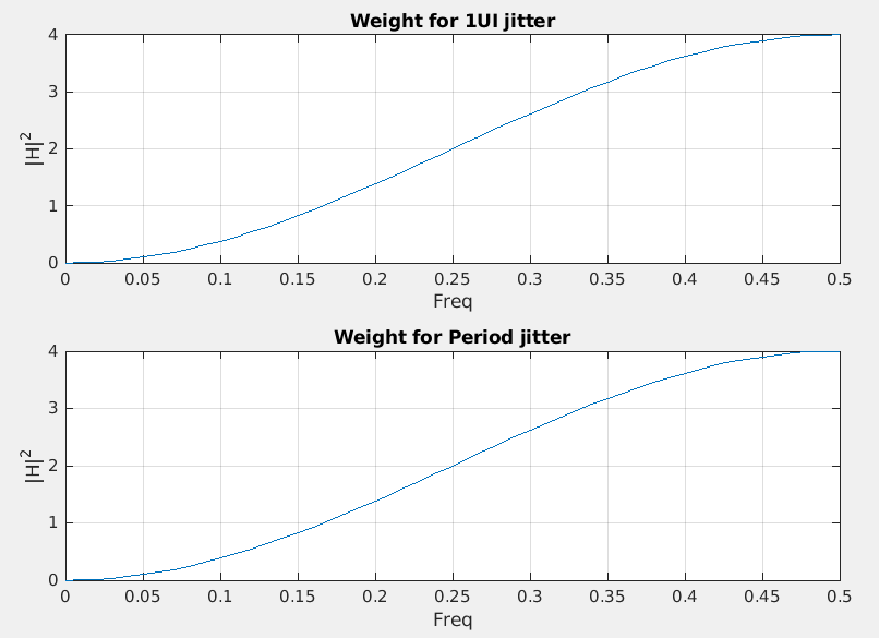
Then 1UI jitter is \(x_{\text{1UI}}(n)=x(n)-x(n-1)\), and Period
jitter is \(x_{\text{Period}}(n)=x(n)-x(n-2)\), which
can be modeled as FIR filter, \(H(\omega) =
1-z^{-k}\), i.e. \(k=1\) for 1UI
jitter and \(k=2\) Period jitter
\[\begin{align}
P_{\text{xx}}'(\omega) &= P_{\text{xx}}(\omega) \cdot \left|
1-z^{-k} \right|^2 \\
&= P_{\text{xx}}(\omega) \cdot \left| 1-(e^{j\omega
T_s})^{-k} \right|^2 \\
&= P_{\text{xx}}(\omega) \cdot \left| 1-e^{-j\omega T_s
k} \right|^2
\end{align}\]
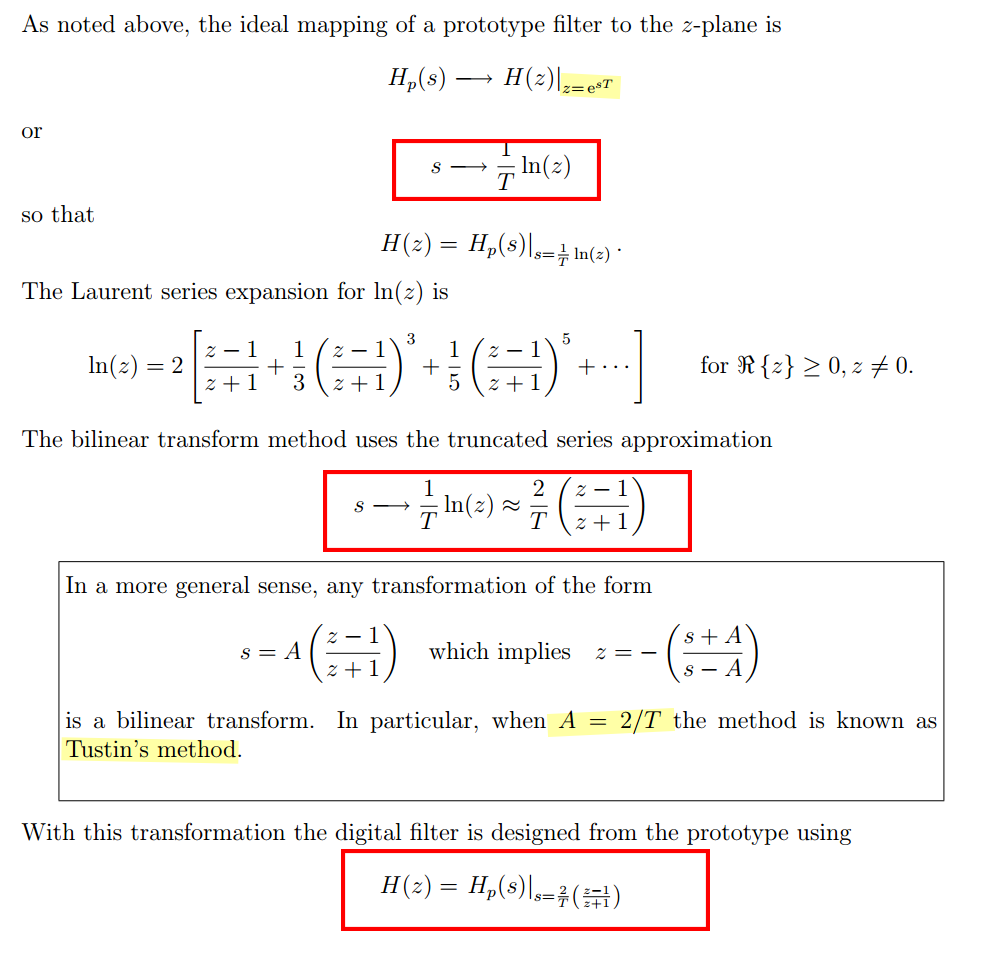
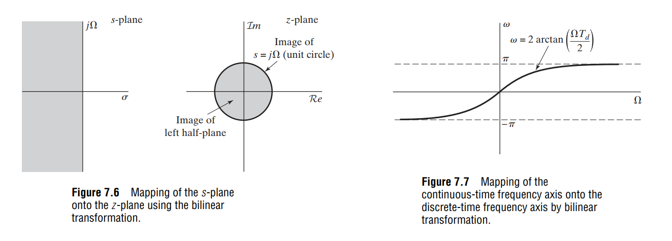
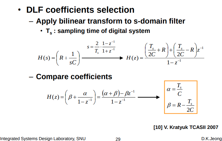
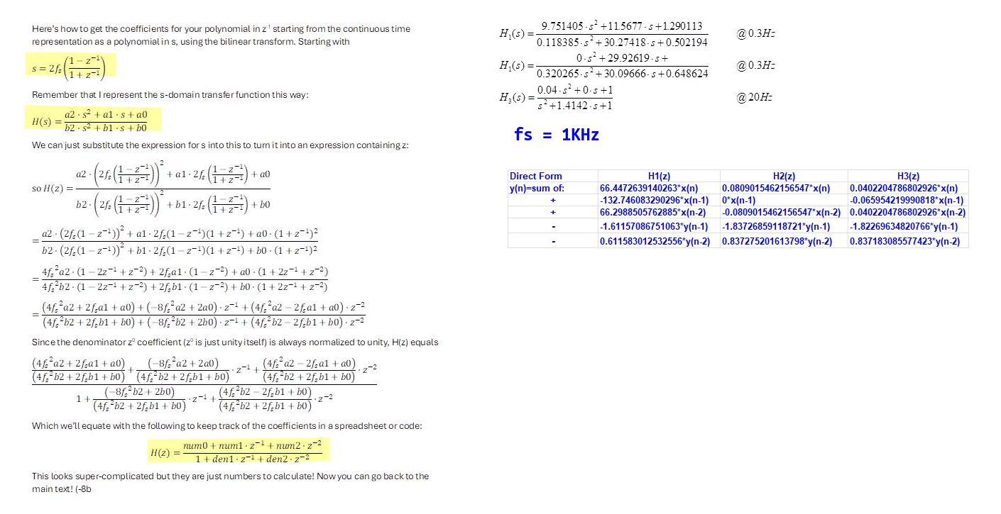
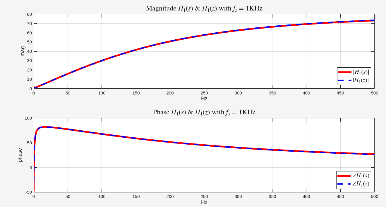
an algebraic transformation between the variables \(s\) and \(z\) that maps the entire
imaginary\(j\Omega\)-axis in the
\(s\)-plane to one revolution of the
unit circle in the \(z\)-plane
\[\begin{align}
z &= \frac{1+s\frac{T_s}{2}}{1-s\frac{T_s}{2}} \\
s &= \frac{2}{T_s}\cdot \frac{1-z^{-1}}{1+z^{-1}}
\end{align}\]
where \(T_s\) is the sampling
period
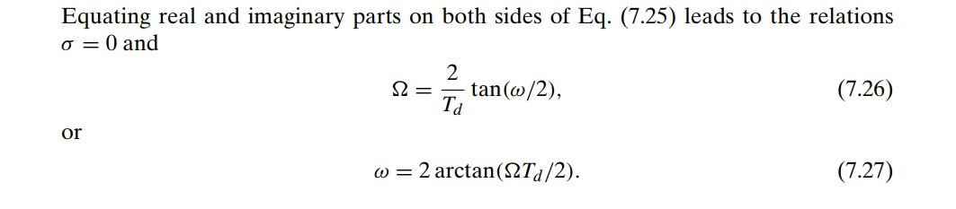
frequency warping:
The bilinear transformation avoids the problem of
aliasing encountered with the use of impulse
invariance, because it maps the entire imaginary axis of the \(s\)-plane onto the unit circle in the \(z\)-plane
impulse invariancecannot be used to
map highpass continuous-time designs to high pass
discrete-time designs, since highpass continuous-time filters are
not bandlimited
Due to nonlinear warping of the frequency axis introduced by the
bilinear transformation, bilinear transformation applied to a
continuous-time differentiator will not result in a
discrete-time differentiator. However, impulse invariance can be applied
to bandlimited continuous-time differentiator
The feature of the frequency response of discrete-time
differentiators is that it is linear with frequency
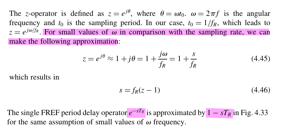
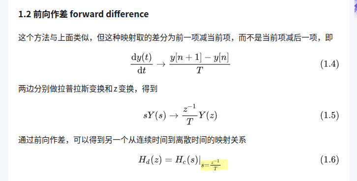
The simple approximation \(z=e^{sT}\approx1+sT\), the first
equal come from impulse invariance
essentially
Because the mapping between the continuous (\(s\)-plane) and discrete domains (\(z\)-plane) cannot be done exactly,
the various design methods are at best approximations
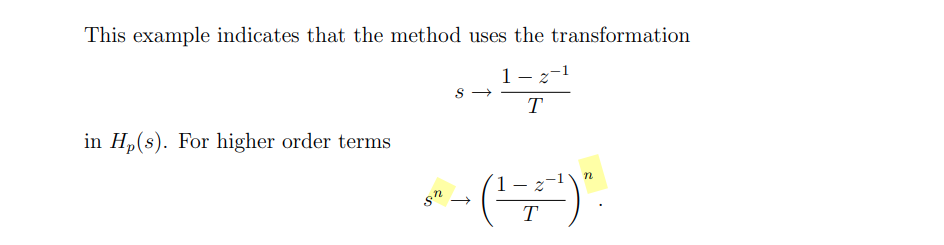
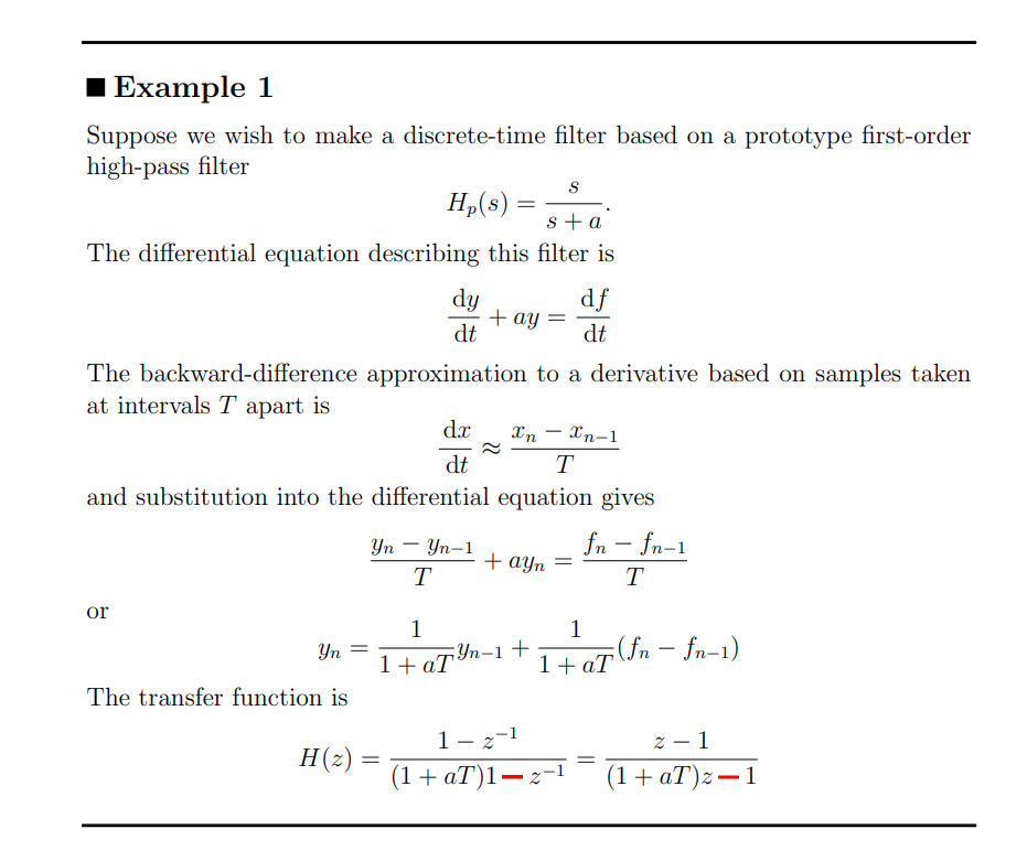
Perhaps the simplest method for low-order systems is to use
backward-difference approximation to
continuous domain derivatives
Note this approximation is not same with
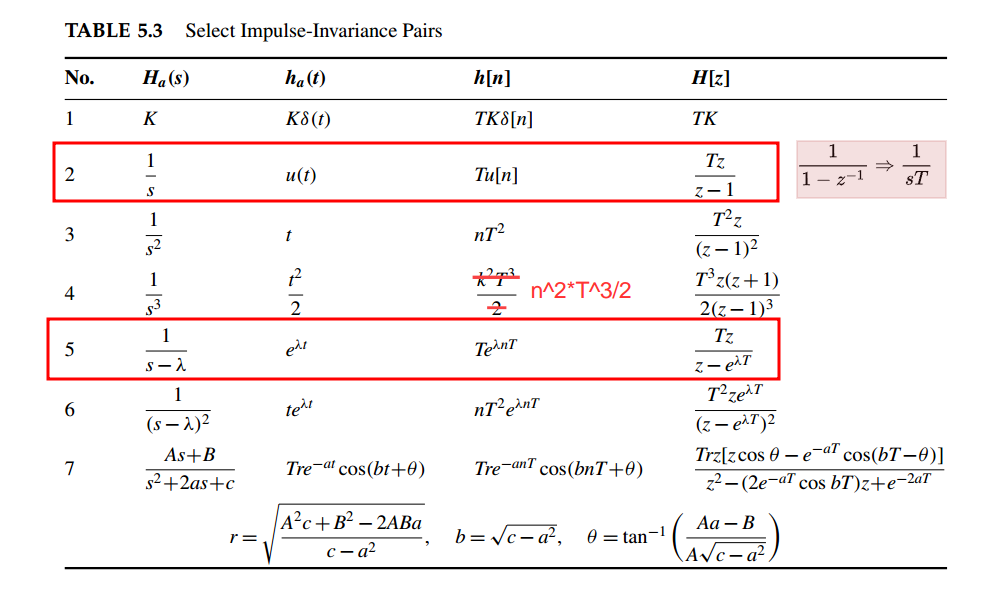
impulse invariance, e.g. \(\frac{1}{s^3} \to
\frac{T^3z(z+1)}{2(-1)^3}\) employing impulse invariance
\[
1- z^{-1} = 1-e^{-j\Omega T} = 1-\cos(\omega T) + j\sin(\Omega T)
\approx 1-1+j\Omega T = s T
\]
That is
\[
s \approx \frac{1-z^{-1}}{T}
\]
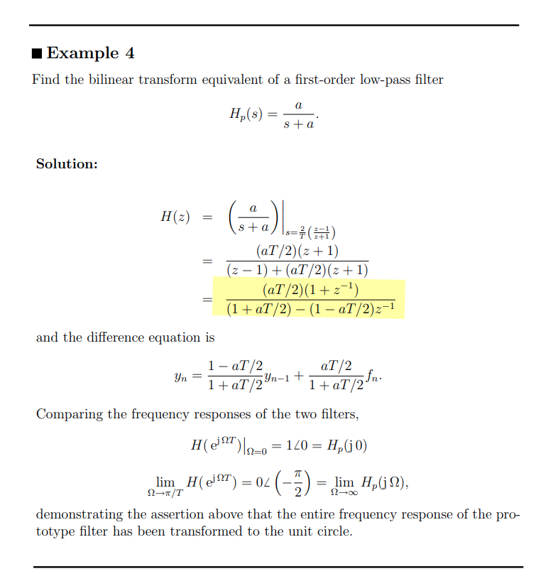
Suppose we wish to make a discrete-time filter based on a prototype
first-order low-pass filter \[
H_p(s) = \frac{1}{s\tau + 1}
\] The differential equation describing this filter is \[
\tau\frac{\mathrm{d}y}{\mathrm{d}t} + y = x
\] then differential equation gives
\[
\tau\frac{y_n-y_{n-1}}{T} + y_n=x_n
\] or \[
(\frac{\tau}{T}+1)y_n - \frac{\tau}{T}y_{n-1} = x_n
\] The transfer function is \[
H(z) = \frac{\frac{T}{T+\tau}}{1-\frac{\tau}{T+\tau}z^{-1}}
\]
or substitute \(s\) with \(\frac{1-z^{-1}}{T}\) into \(H_p(s)\)\[
H_p(z) = \frac{1}{\tau\frac{1-z^{-1}}{T} + 1} =
\frac{\frac{T}{T+\tau}}{1-\frac{\tau}{T+\tau}z^{-1}}= \frac{\alpha}{1
+(\alpha -1)z^{-1}}
\] where \(\alpha =
\frac{T}{\tau+T}\)
Further, if time constants much longer than the time step \(\tau \gg T\)\[\begin{align}
\frac{T}{T+\tau}& = \frac{T}{\tau}\cdot \frac{\tau}{T+\tau}\approx
\frac{T}{\tau} \\
\frac{\tau}{T+\tau} &= \frac{\tau -
T}{\tau}\cdot\frac{\tau^2}{\tau^2-T^2} \approx \frac{\tau - T}{\tau} =
1- \frac{T}{\tau}
\end{align}\]
Then the first-order low pass filter \[
H_p(z) \approx \frac{ \frac{T}{\tau}}{1 +( \frac{T}{\tau} -1)z^{-1}} =
\frac{\beta}{1 +(\beta -1)z^{-1}}
\] where \(\beta =
\frac{T}{\tau}\)
1 2 3 4 5 6 7 8 9 10 11 12 13
# https://www.dsprelated.com/showarticle/1517/return-of-the-delta-sigma-modulators-part-1-modulation # https://www.embeddedrelated.com/showarticle/779.php defshow_dsmod_samplewave(t,x,dsmod,args=(1,),tau=0.05, R=1, fig=None, return_handles=False, filter_dsmod=False): dt = t[1]-t[0] if filter_dsmod: x1 = dsmod(x, *args,R=R, modulate=False) else: x1 = x y = dsmod(x,*args,R=R) a = dt/tau yfilt = scipy.signal.lfilter([a],[1,a-1],y) xfilt = scipy.signal.lfilter([a],[1,a-1],x1)
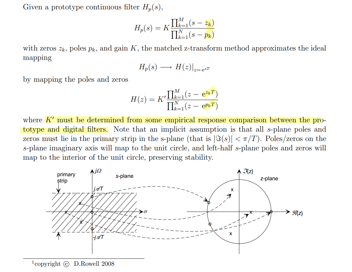
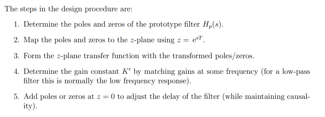
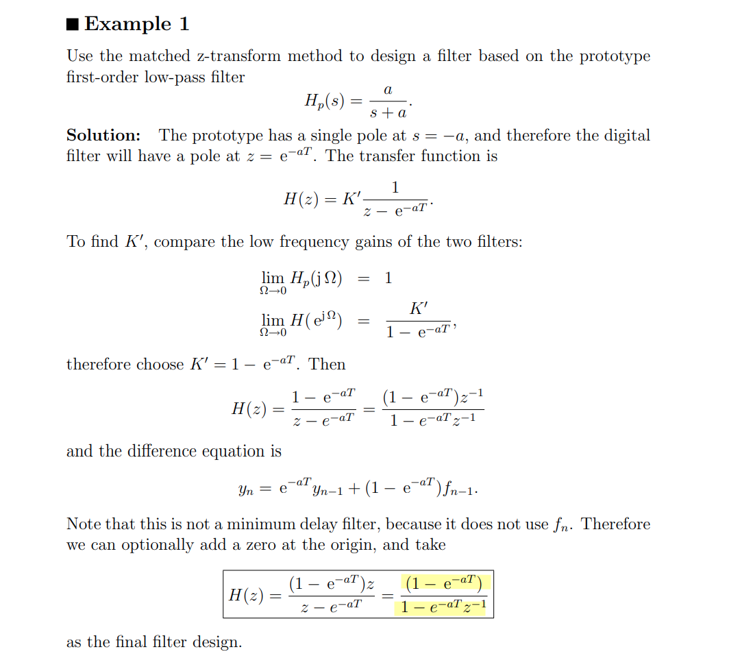
The matched Z-transform method, also called the
pole-zero mapping or pole-zero matching method, and
abbreviated MPZ or MZT
\[
z = e^{sT}
\]
1 2 3 4 5 6 7 8 9 10
% https://www.dsprelated.com/showarticle/1642.php
%II One-pole RC filter model Ts= 1/fs; Wc= 1/(R*C); % rad -3 dB frequency fc= Wc/(2*pi); % Hz -3 dB frequency a1= -exp(-Wc*Ts); b0= 1 + a1; % numerator coefficient a= [1 a1]; % denominator coeffs y_filt= filter(b0,a,y); % filter the DAC's output signal y
Impulse Invariance
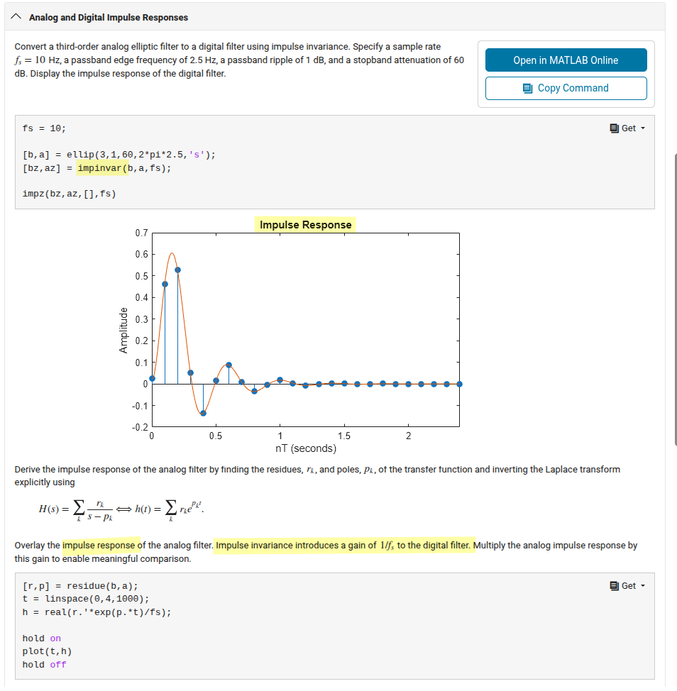
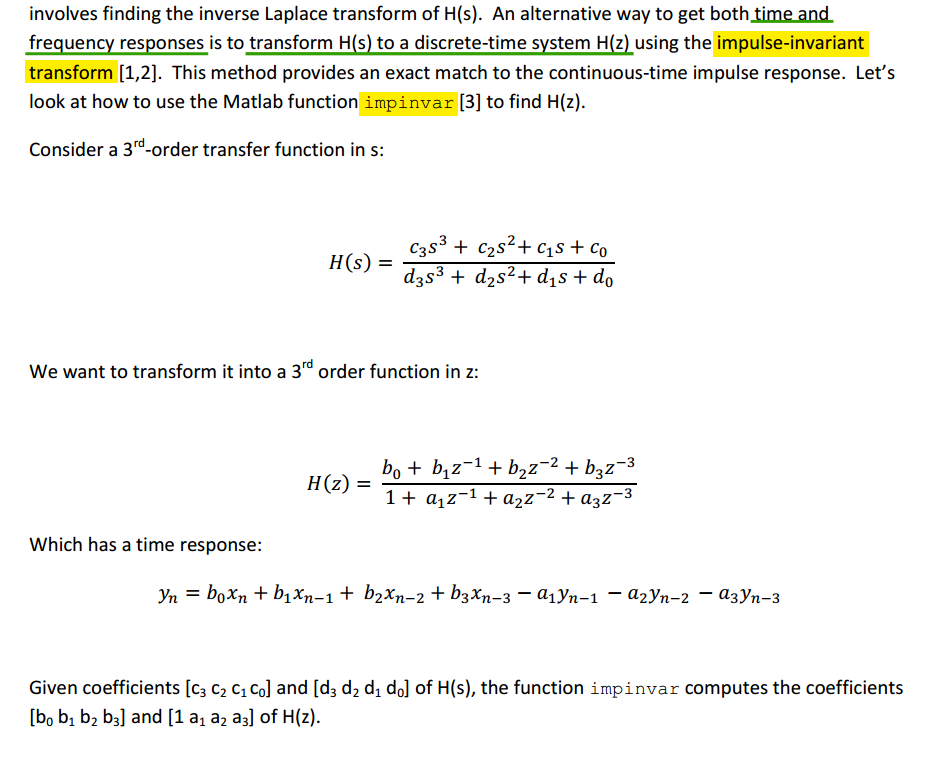
(impinvar)
To extend the accurate frequency range, we would need to
increase the sample rate
impulse-invariant transform is not appropriate for high-pass
responses, because of aliasing
errors
Note \(h[n] = Th_c(nT)\), Multiply
the analog impulse response by this gain to
enable meaningful comparison (other response, like step, the
amplitude correction is not needed)
% https://www.dsprelated.com/showarticle/1055.php % modified by hguo, Sun Jun 22 09:21:48 AM CST 2025
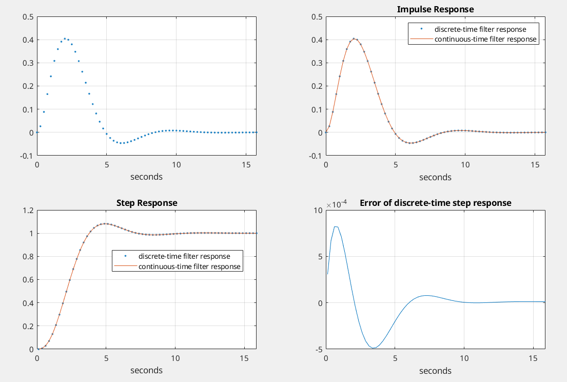
% butter_3rd_order.m 6/4/17 nr % Starting with the butterworth transfer function in s, % Create discrete-time filter using the impulse invariance xform and compare % its time and frequency responses to those of the continuous time filter. % Filter fc = 1 rad/s = 0.159 Hz
% I. Given H(s), find H(z) using the impulse-invariant transform fs= 4; % Hz sample frequency % 3rd order butterworth polynomial num= 1; den= [1221]; [b,a]= impinvar(num,den,fs); % coeffs of H(z) %[b,a]= bilinear(num,den,fs)
% II. Impulse Response and Step Response % find discrete-time impulse response Ts= 1/fs; N= 16*fs; n= 0:N-1; t= n*Ts; x= [1, zeros(1,N-1)]; % impulse x= fs*x; % make impulse response amplitude independent of fs y= filter(b,a,x); % filter the impulse subplot(2,2,1),plot(t,y,'.'),grid, xlabel('seconds')
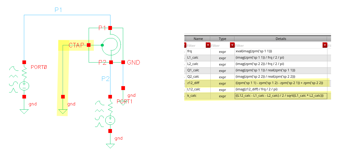
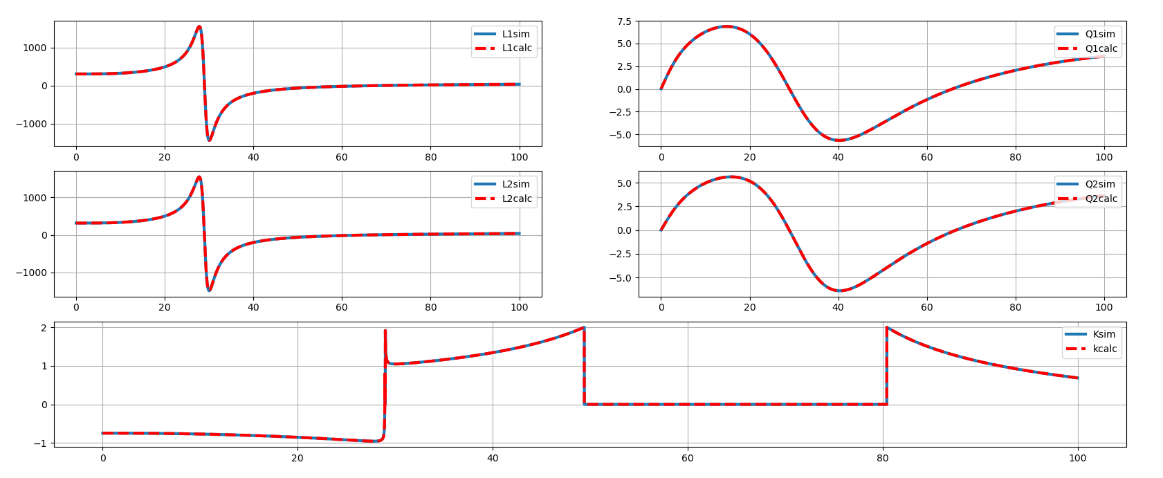
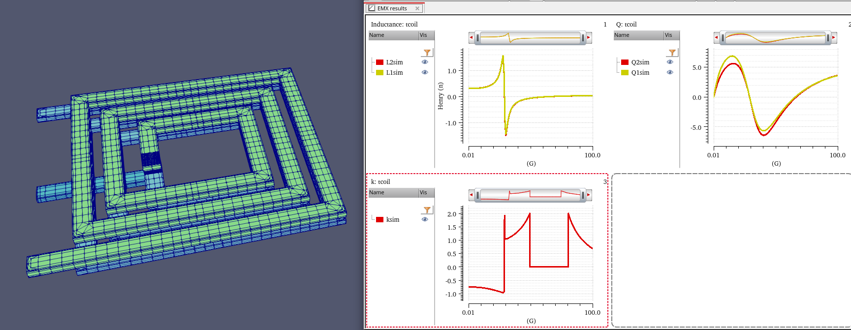
In recent versions (specifically EMX2024 and later),
(k (if ((abs kk) < 2.0) kk 0.0))) was updated to
(k (if ((abs kk) < 2.0) -kk 0.0))) to ensure the
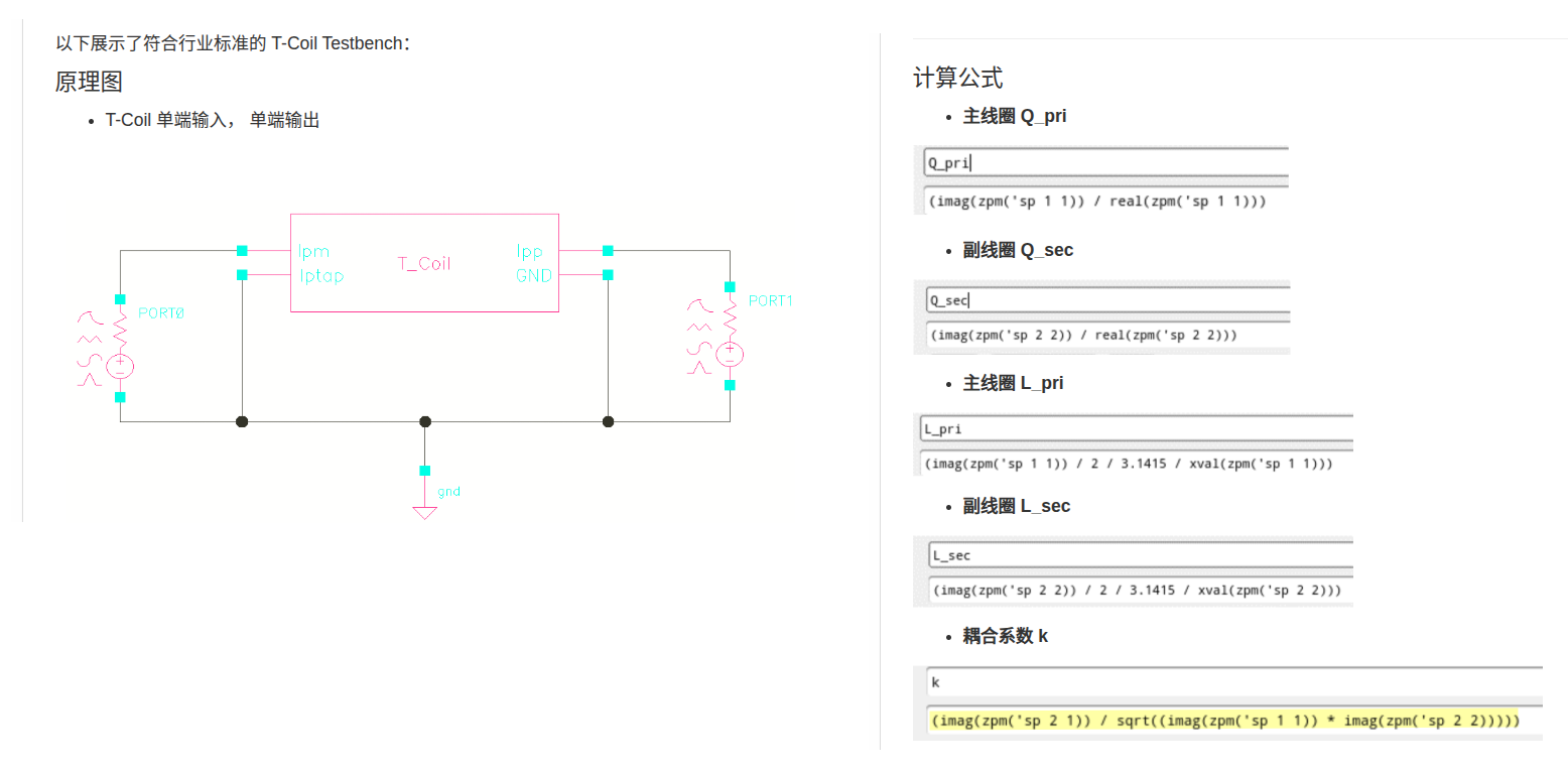
correct sign for k
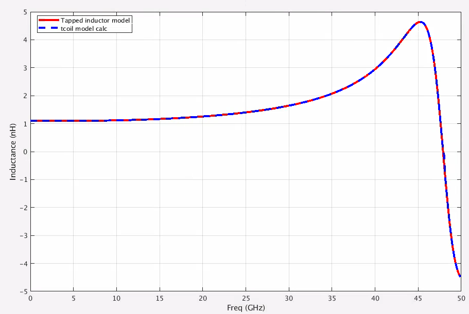
tcoil and tapped inductor share same EM simulation result, and use
modelgen with different model formula.
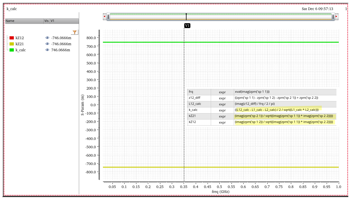
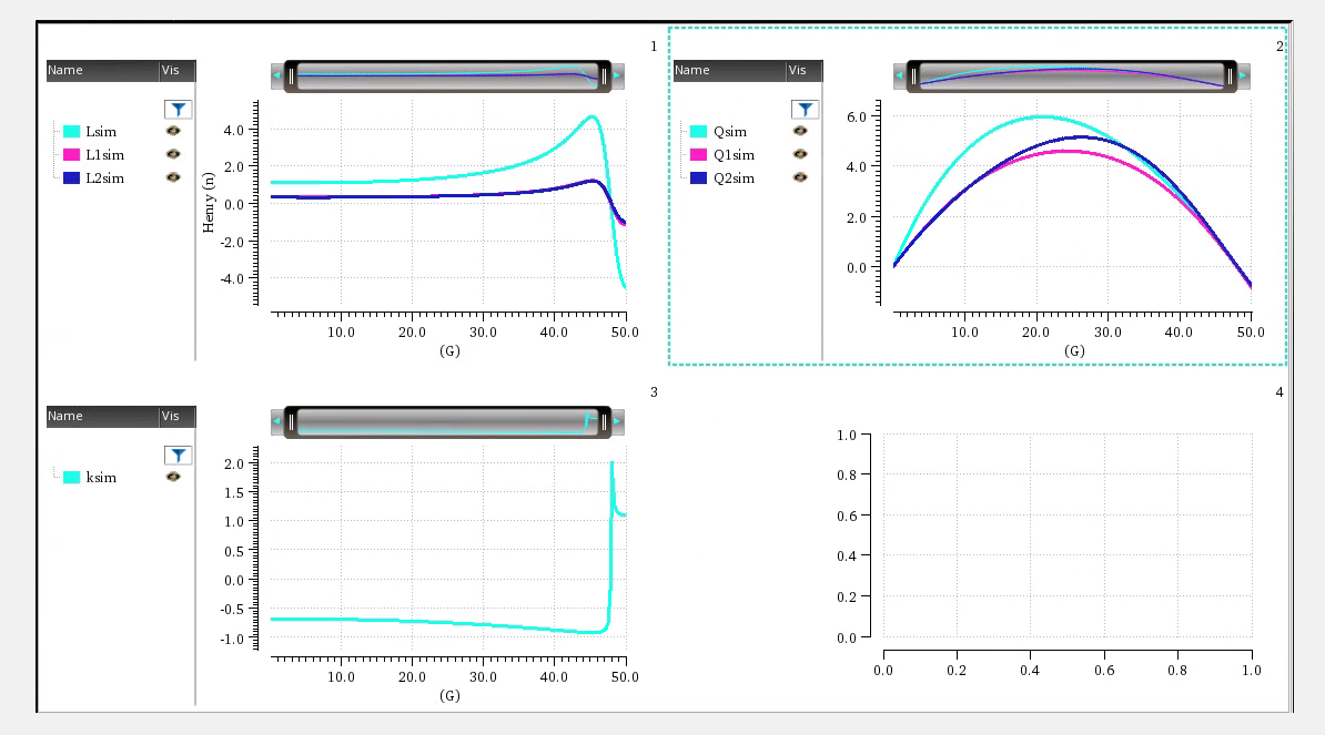
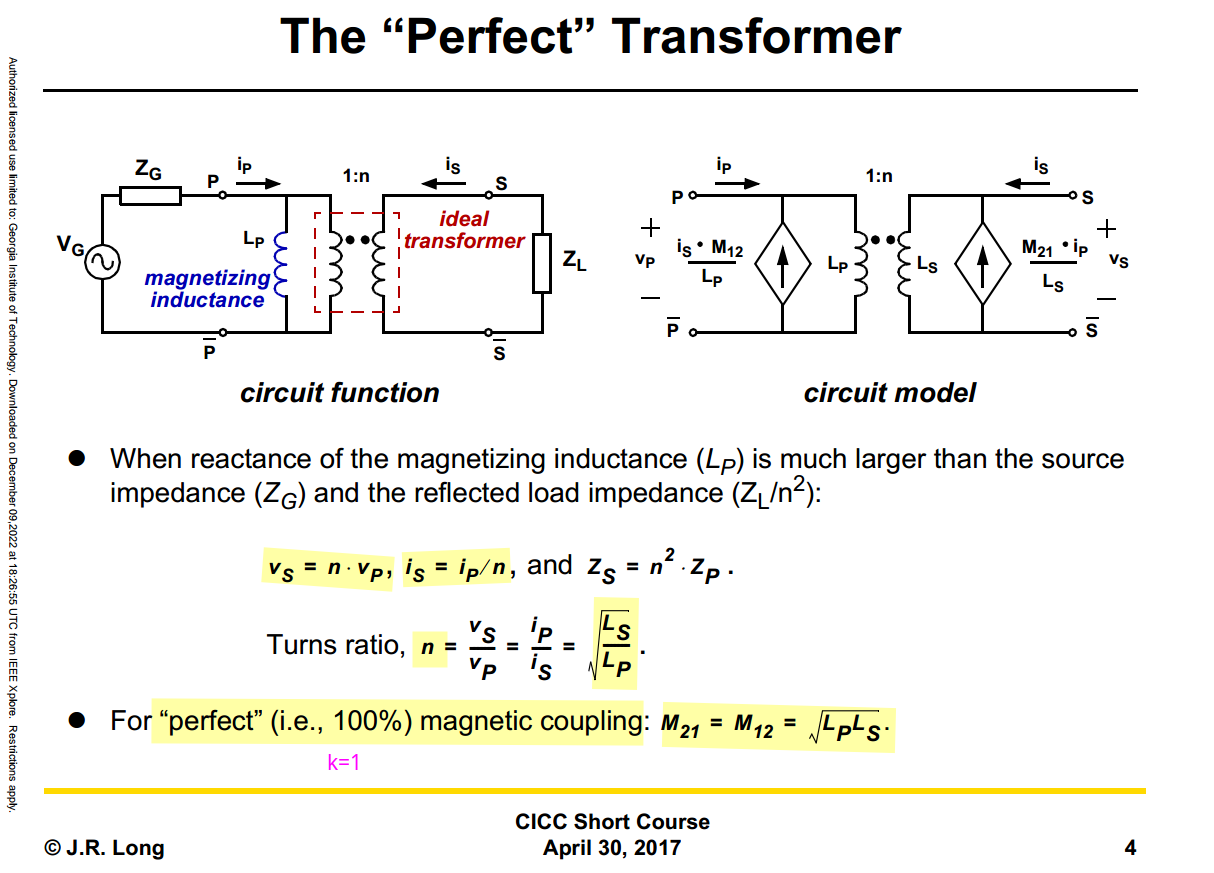
The relationship is \[
L_{\text{sim}} = L1_{\text{sim}}+L2_{\text{sim}}+2\times k_{\text{sim}}
\times \sqrt{L1_{\text{sim}}\cdot L2_{\text{sim}}}
\] where \(L1_{\text{sim}}\),
\(L2_{\text{sim}}\) and \(k_{\text{sim}}\) come from tcoil model
result, \(L_{\text{sim}}\) comes from
tapped inductor model result
\(k_{\text{sim}}\) in EMX have
assumption, induce current from P1 and P2 Given Dot Convention:
Same direction : k > 0
Opposite direction : k < 0
So, the \(k_{\text{sim}}\) is
negative if routing coil in same direction
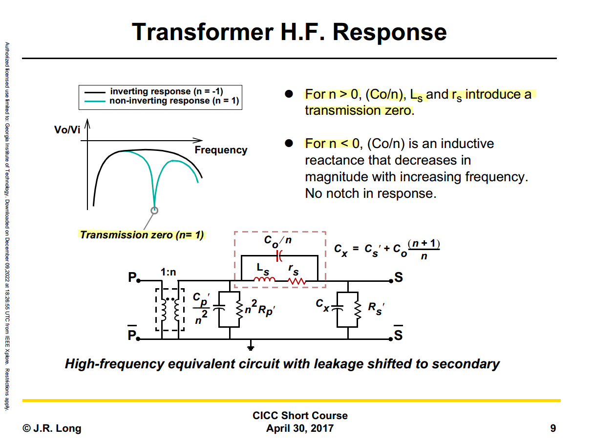
J. R. Long, "On-chip transformer design and application to RF and
mm-wave front-ends," 2017 IEEE Custom Integrated Circuits Conference
(CICC), Austin, TX, USA, 2017
A. Bevilacqua, "Tutorial: Fundamentals of Integrated Transformers:
from Principles to Applications," 2020 IEEE International
Solid-State Circuits Conference - (ISSCC), San Francisco, CA, USA,
2020
—, "Fundamentals of Integrated Transformers: From Principles to
Applications," in IEEE Solid-State Circuits Magazine, vol. 12,
no. 4, pp. 86-100, Fall 2020
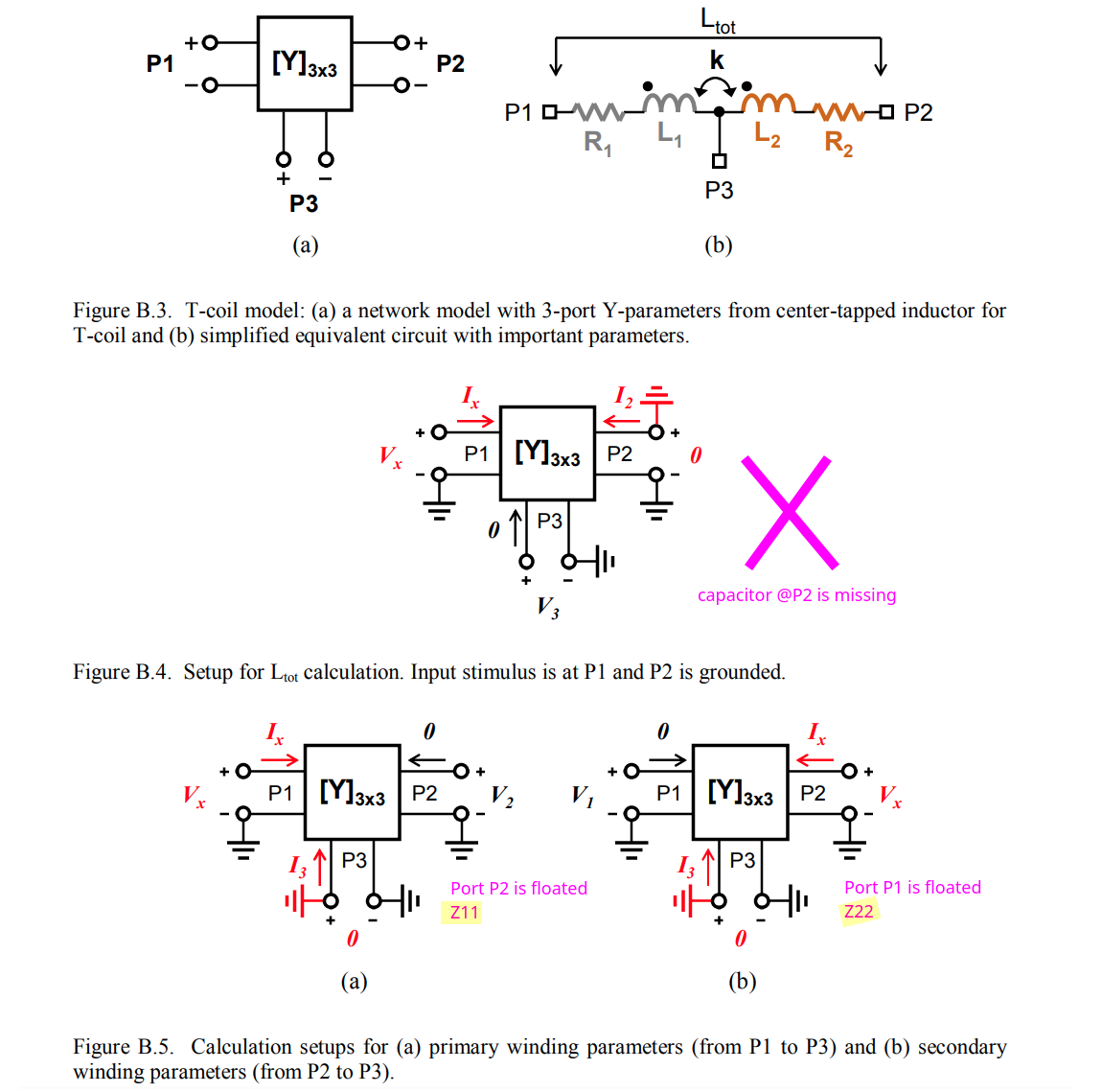
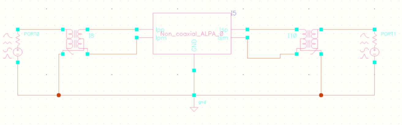
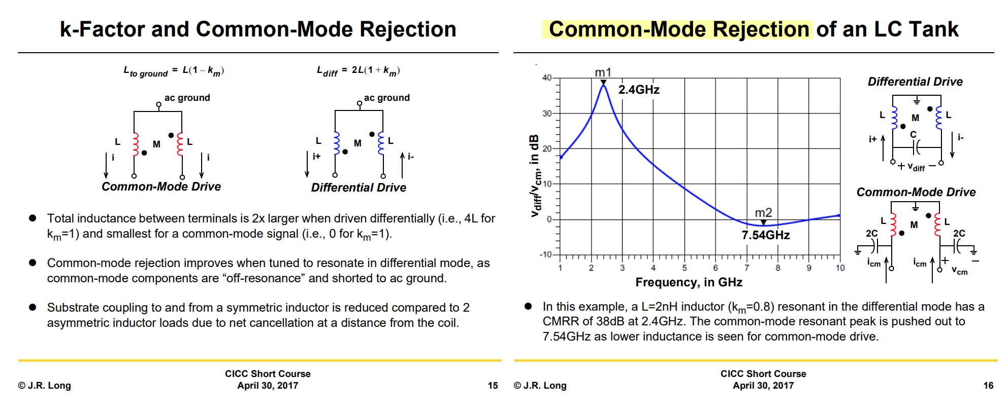
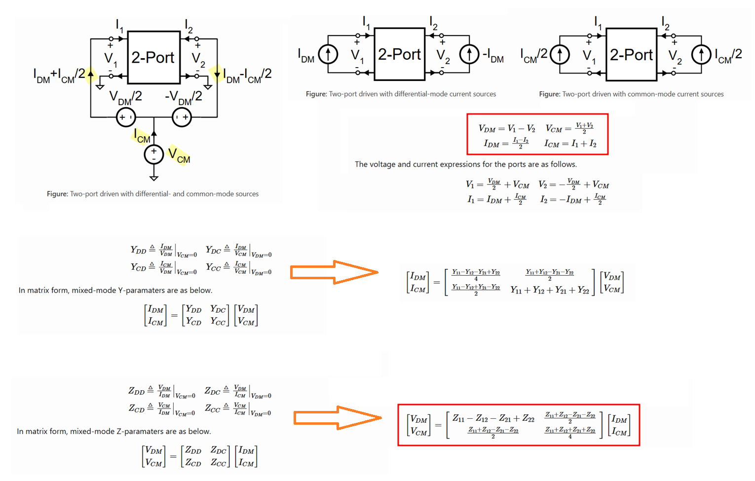
When a differential-voltage stimulus, i.e., \(V_1=-V_2\), is applied, the
differential-mode current can be calculated from the simulated branch
currents as \(I_{DM}=(I_1-I_2)/2\).
When a differential-current stimulus, i.e., \(I_1=-I_2\), is applied, the
differential-mode voltage can be calculated from the simulated node
voltages as \(V_{DM}=V_1-V_2\).
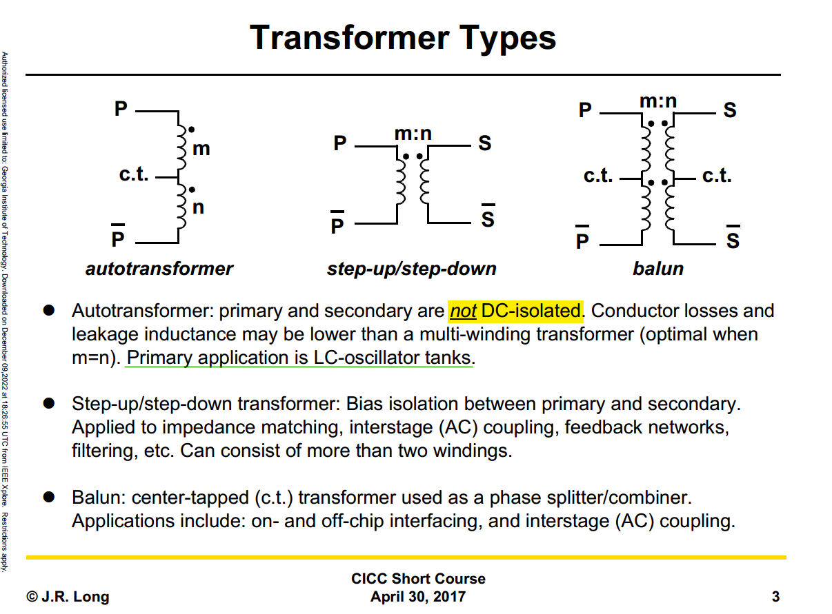
For a center-tapped (CTAP) inductor with the center tap
AC-grounded, define
For the usual CT winding orientation, when both port currents are
defined from the outer terminals toward the grounded center
tap, the two halves have opposite dot orientation. Therefore,
the 2-port impedance matrix is
drawing layer rectangle pin and specify
Access Direction as intended
check Cadence pins in Advanced
options
When only rectangular pins are present, they are consistently
assigned as driven ports, regardless of the "Cadence pins" selection
state
check ports used for simulation use
GDS view - EMX
EMX Synthesis Kits
Synthesis is a capability of the EMX Pcell library
and uses scalable model data pre-generated by Continuum for a specific
process and metal scheme combination.
Synthesis is supported by the Pcells that are suffixed
_scalable, and these Pcells have the additional fields
and buttons needed for synthesis.
Assume CT i.e. port 3 in S-parameter is grounded,
(z (EMX_differential (nth 0 ys) (nth 1 ys) (nth 3 ys) (nth 4 ys)))
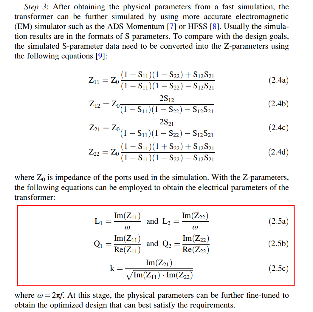
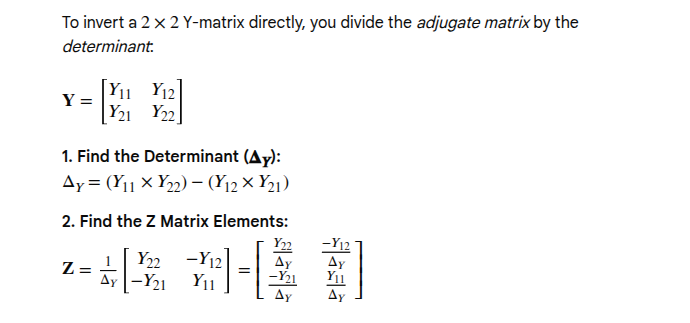
obtain differential impedance with \(Y_{11}\), \(Y_{12}\), \(Y_{21}\) and \(Y_{22}\). \[
Y =
\begin{bmatrix}
Y_{11} & Y_{12}\\
Y_{21} & Y_{22}
\end{bmatrix}
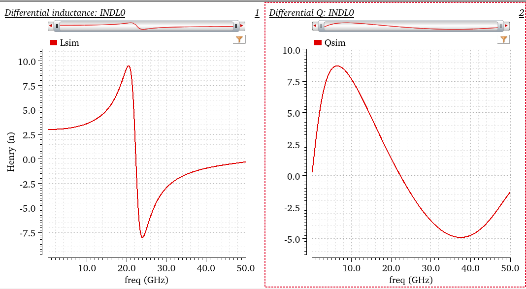
\] Finally, differential inductance and Q are obtained, shown as
below
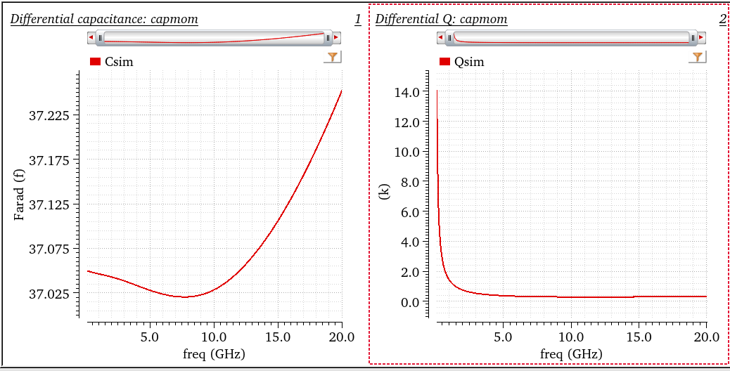
First obtain differential impedance, \(Z_{diff}\) then apply series equivalent
model \[\begin{align}
C_{diff} = -\frac{1/Im(Z_{diff})}{2\pi f} \qquad Q_{diff} =
-\frac{Im(Z_{diff})}{Re(Z_{diff})}
\end{align}\]
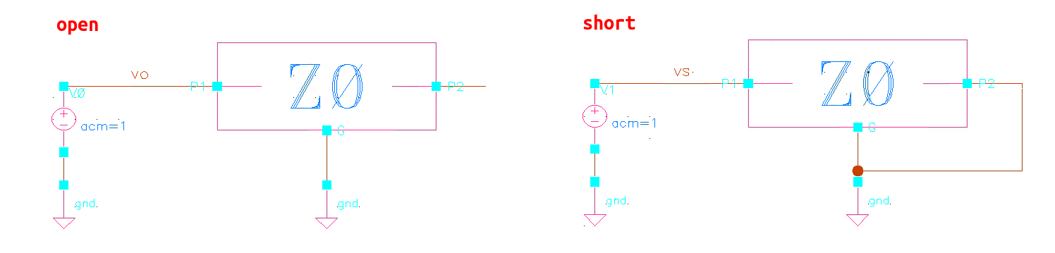
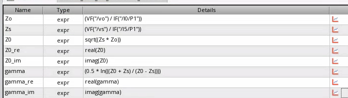
propagation constant is given as \[
\gamma \cdot l = \frac{1}{2}\log\left( \frac{Z_0+Z_s}{Z_0-Z_s} \right)
\]
\(Z_s\) depends on the length of
tline
The relationship between these parameter and geometry of the
transmission line \[
Z_0 = \sqrt{\frac{R+j\omega L}{G+j\omega C}} \qquad \gamma =
\sqrt{(G+j\omega C)(R+j\omega L)}
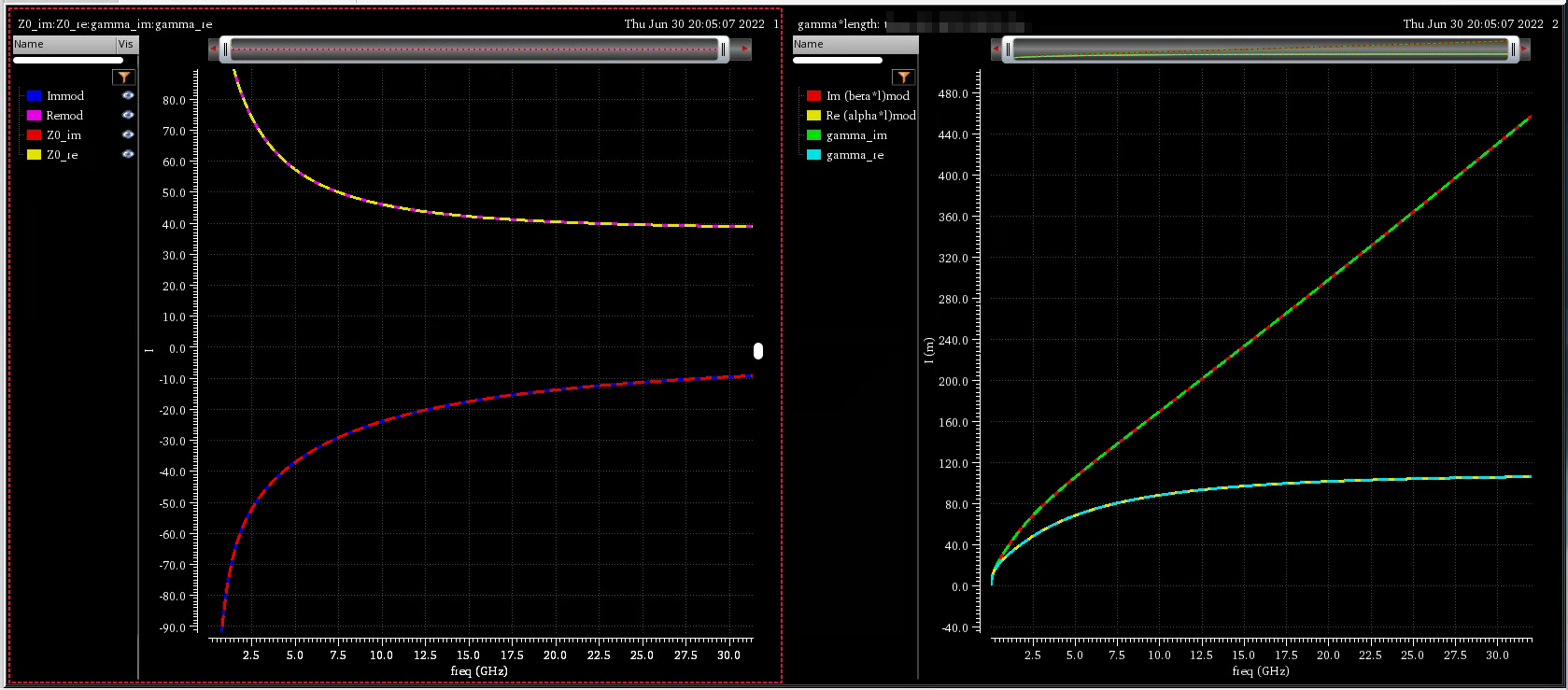
\] EMX plot the real and imaginary part of \(Z_0\), \(\alpha\) and \(\beta\) of \(\gamma\)
Note EMX plot \(\operatorname{Re}\{Z_0\}\) ,\(\operatorname{Im}\{Z_0\}\), \(\alpha\cdot l\) and \(\beta\cdot l\)
EMX autoplot
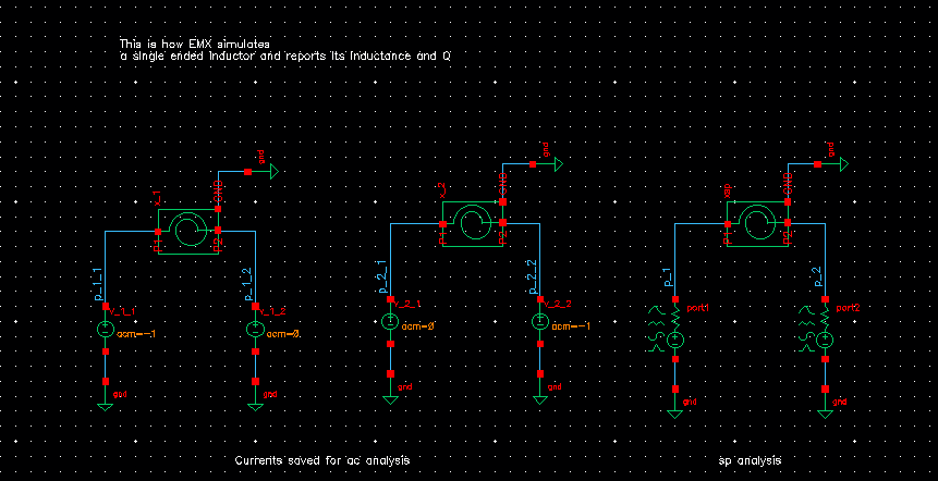
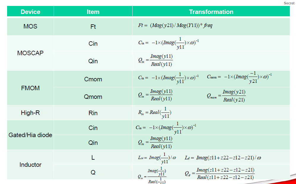
using AC simulation, and inductor's parallel model or series
model
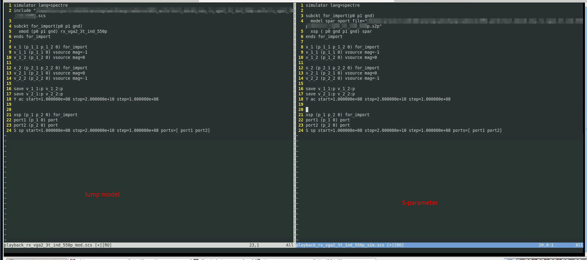
That is to say: both sp (network parameter) and
ac (impedance) can be used to plot inductance, Q value.
usually EMX choose ac method
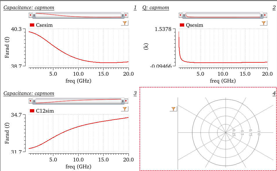
left 2 figures are used for AC simulation, \(Y_{nn}\) can be obtained conveniently
So, the EMX model and foundary model is consistent.
O. Hanay, J. Hulsman and R. Negra, "Three-Port S-Parameter based
characterization of integrated bridged-T-Coils," 2019 12th German
Microwave Conference (GeMiC), Stuttgart, Germany, 2019, pp. 268-271
[https://sci-hub.se/10.23919/GEMIC.2019.8698123]
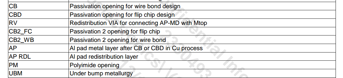
pad & bump
EMX process file contain M0 up to RDL-AP
PM, CB2_FC, UBM is in the chip package
PEX extract up to RDL-AP as expected
DC model
quick find routing resistance
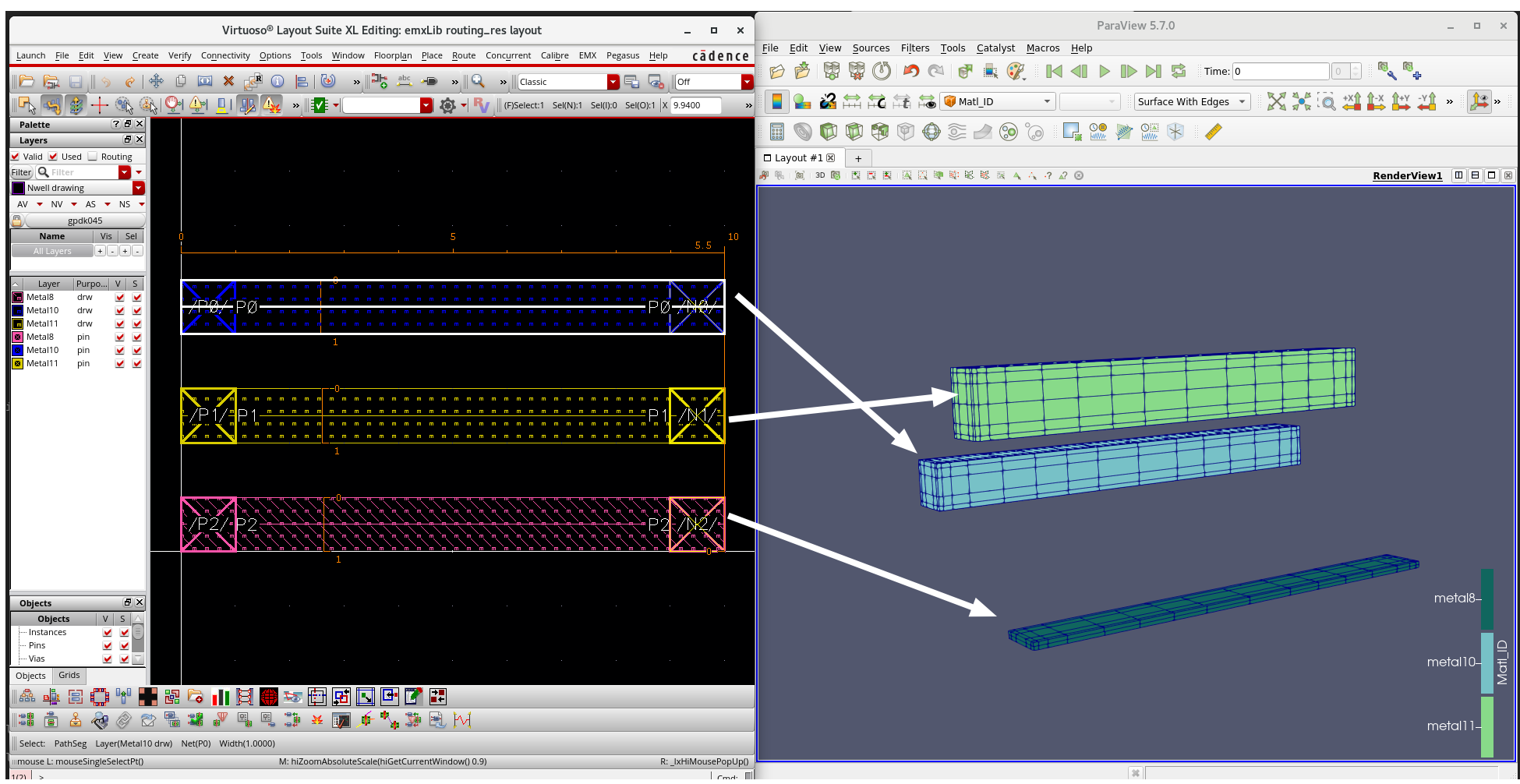
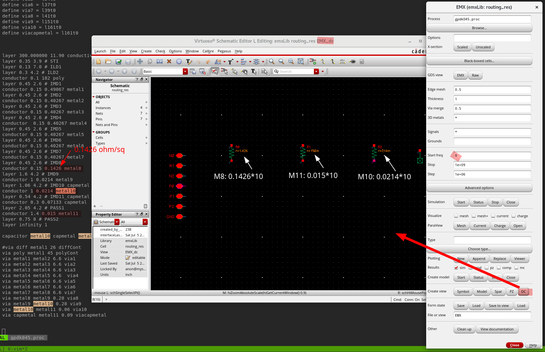
GPDK045 metal resistor model is not consistent with
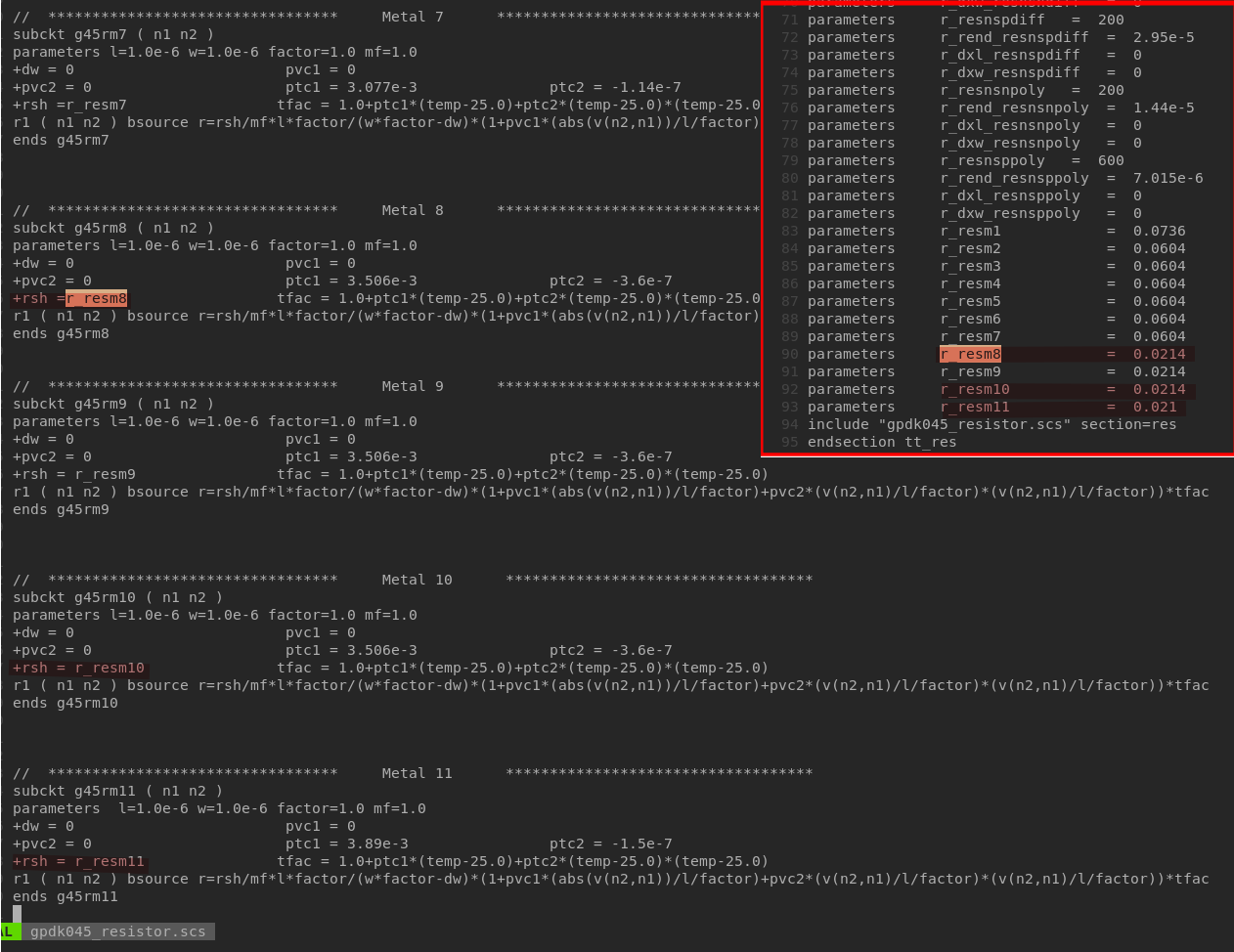
its process file on sheet resistance
For accurate results from EM, the current in the
model needs to flow in the physically correct way,
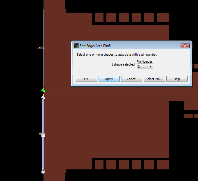
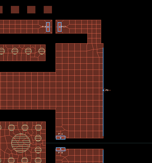
similar to the hardware. With edge/area pins, we can help Momentum to
create the physically correct current flow in complex port
configurations.
Edge port with user defined location and
size
Area pins with user defined location and
size
If we manually control the area pin size, Momentum will equally
distribute the injected current across that area
Port Referencing in
S-Parameters
Peter J. Pupalaikis, DesignCon 2026: Port referencing in S-parameters
- Critical Insights You Need to Know
TODO 📅
same Pin names in EMX
It remains shrouded in myth
EMX Setup Tricks
Process file*
Process file encryption mostly for advanced nodes, like TSMC 16nm
Finfet, whose process file is encrypted.
Use --key=EMXkey in the EMX Advanced
options
GDSviewer has two options
EMX: shows the final gds sent to EMX for simulation after it has
been processed by EMX
Raw: shows the raw gds
If there are port name with the # sign, it means EMX
sees a port but it is not in the signal list.
EMX Accuracy
Edge mesh: controls layout discretization in the X-Y plane
For MoM capacitors, use the edge mesh to be the same as the width of
the finger (for example, 0.1um).
Thickness: controls layout discretization in the Z
dimension
3D metals: skips all 2D assumptions about conductors and their
currents and charges
If you set 3D metals to * then all metals
are treated as 3D
For Inductor type structures, only thick metal needs 3D.
For MoM, all layers are needed.
Ports entered in Grounds will cause these nets to be
grounded; these ports will not show up in the S-parameter result.
Setup Temperature
EMX: --temperature=100
ParaView
If check ParaView related options when ParaView is not setup
properly, EMX simulation stop at Creating mesh... without
waring or errors (version 6.2).
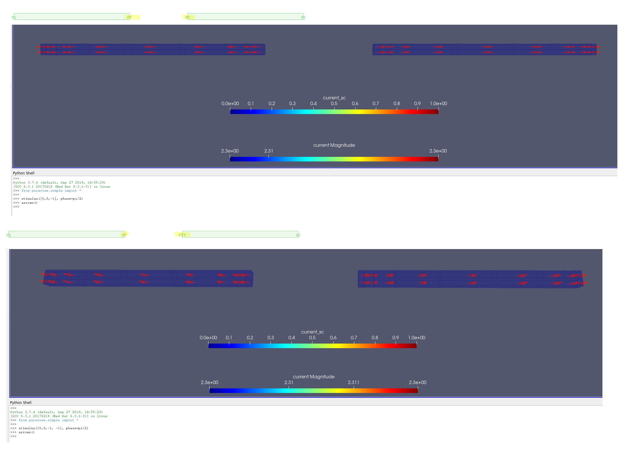
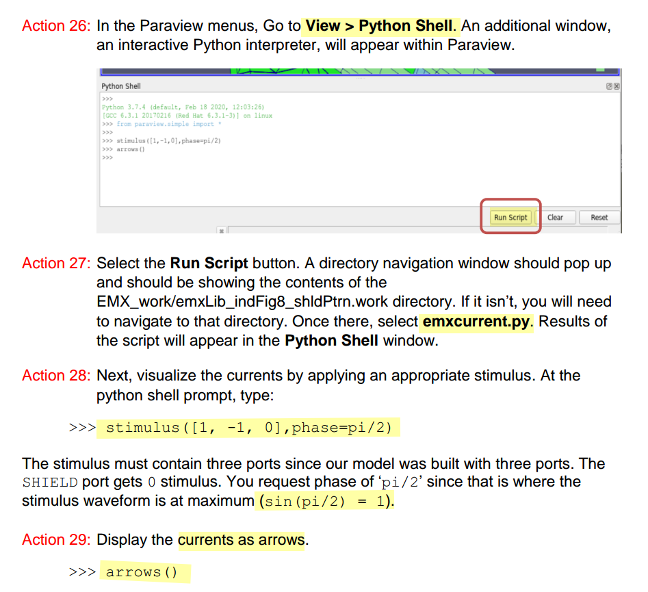
Paraview & stimulus
LVS check
LVS issue for circuits with customized devices
auCdl: Analog and Microwave CDL, is a netlister used for creating
CDL netlist for analog circuits
auLVS: Analog and Microwave LVS, is used for analog circuit LVS
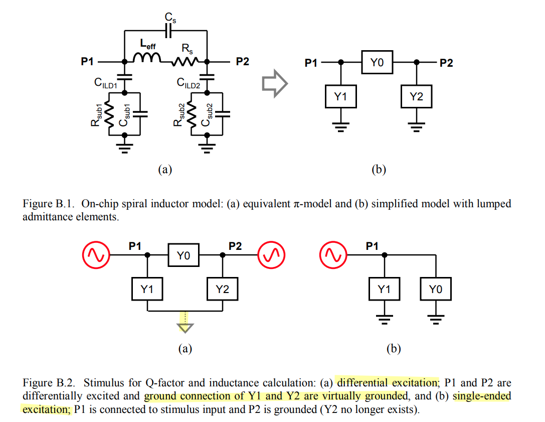
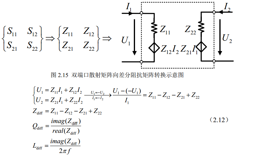
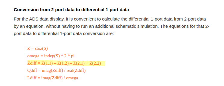
compute the differential impedance \(Z_\text{diff} = Z_{11} - Z_{12} - Z_{21} +
Z_{22}\), which is the impedance seen between the two ports of
the inductor under differential excitation
1 2 3 4 5 6 7 8 9 10 11 12 13 14 15 16 17 18 19
import numpy as np import skrf as rf
f = results.freq * 1e9# GHz -> Hz w = 2 * np.pi * f
ports = results.port_names n = len(ports)
S = np.zeros((len(f), n, n), dtype=complex) for i, pi inenumerate(ports): for j, pj inenumerate(ports): S[:, i, j] = results[(pi, pj)].complex
ntwk = rf.Network(f=f, s=S, f_unit="hz") Z = ntwk.z
The loss function measures the total
squared error between the model and the simulated data across all
frequencies: \[
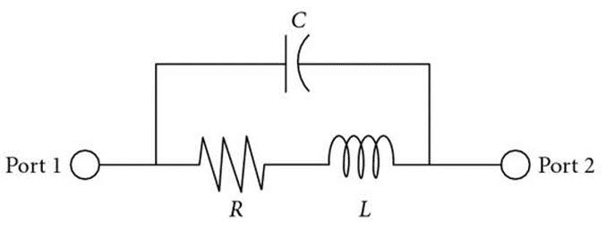
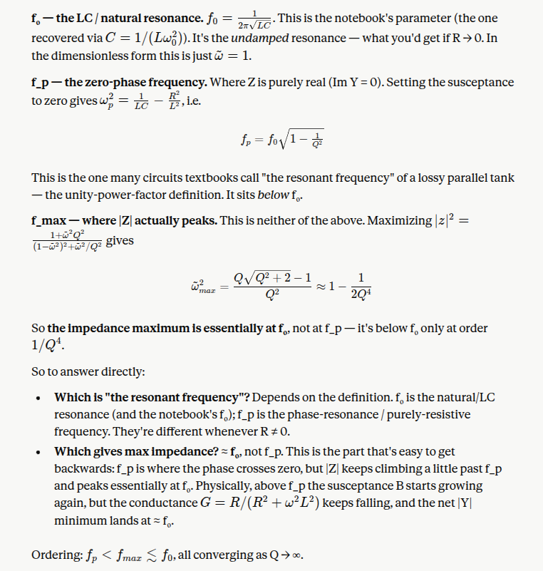
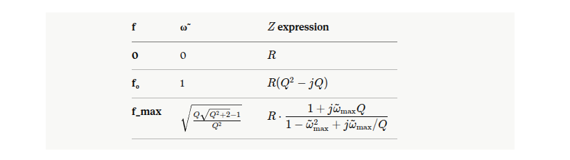
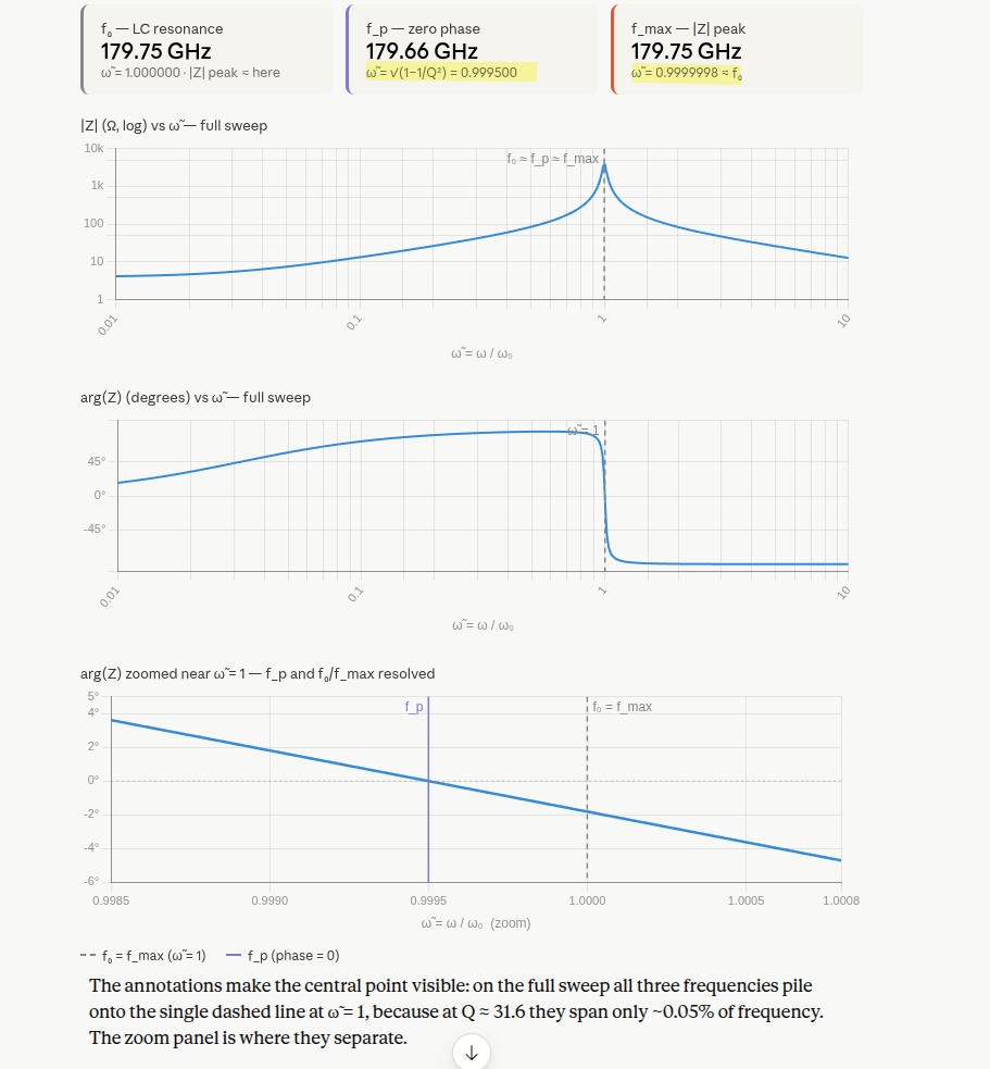
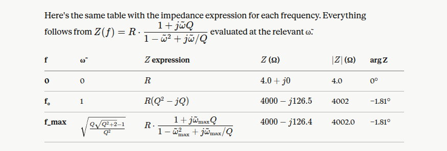
\mathcal{L}(f_0, Q, R) = \sum_k \left| Z_\text{sim}(f_k) - R \cdot
z(f_k/f_0, Q) \right|^2
\]
1 2 3 4 5 6 7 8 9 10 11
defz_rlc(w, Q): return (1 + 1j * w * Q) / (1 - w**2 + 1j * w / Q)
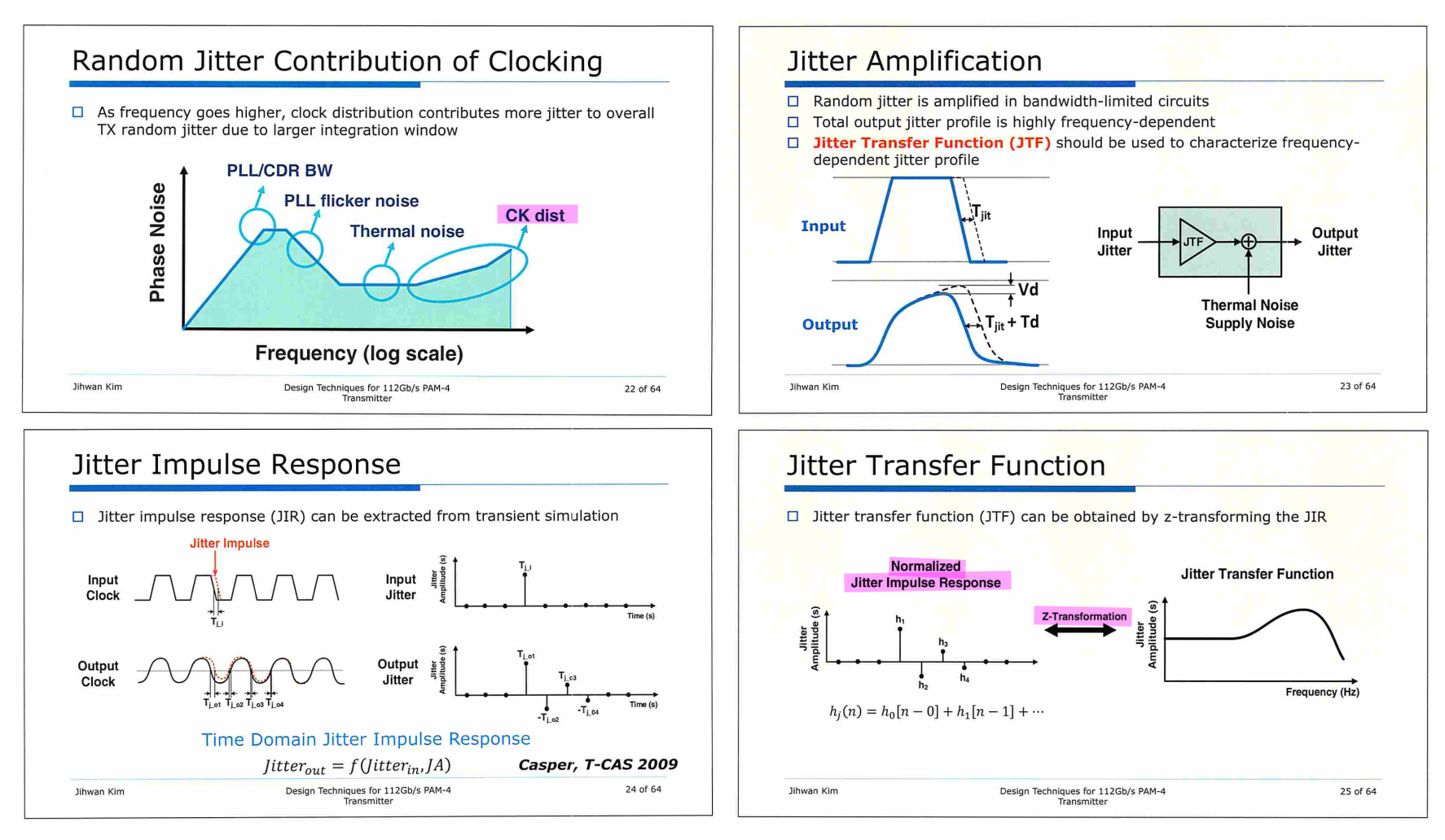
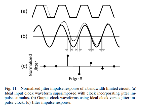
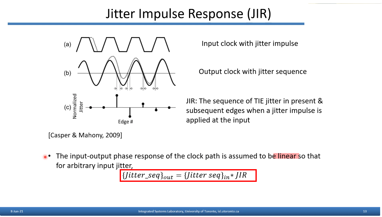
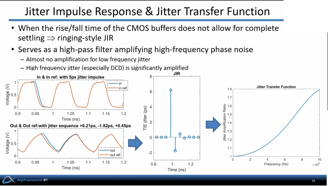
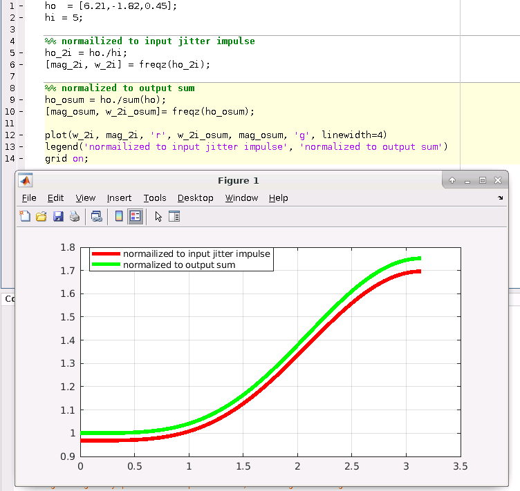
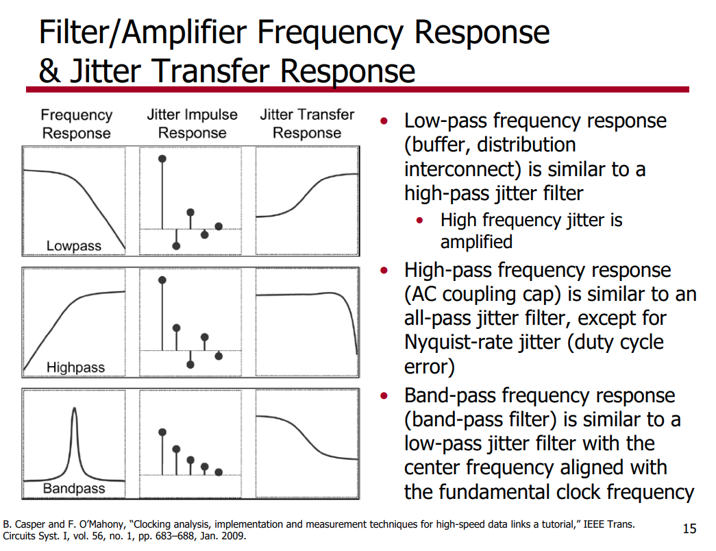
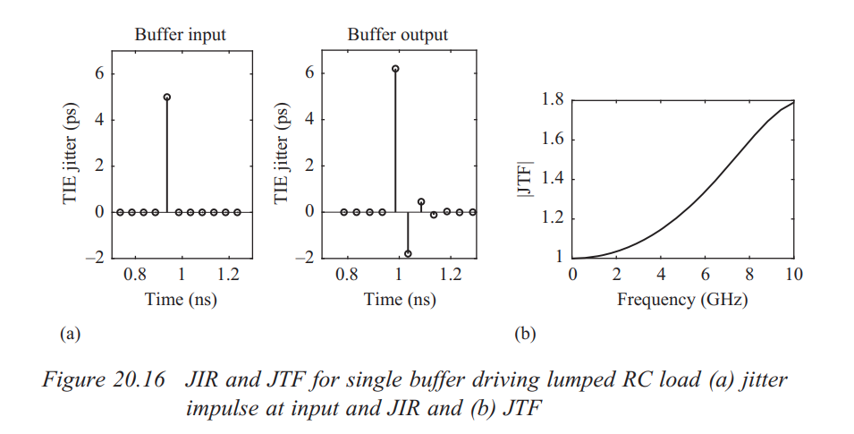
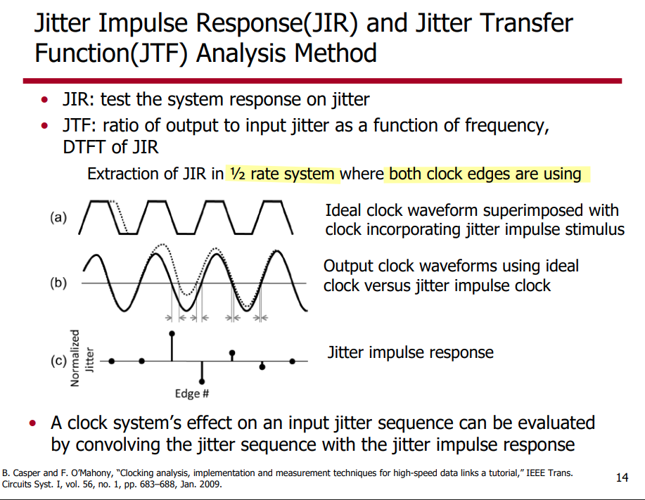
discrete time jitter impulse response
(normalized to the input jitter stimulus similar to the procedure used
to represent a conventional system impulse response)
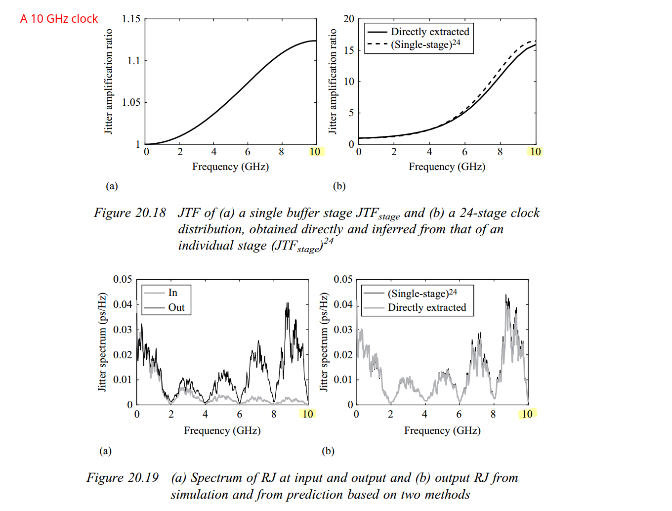
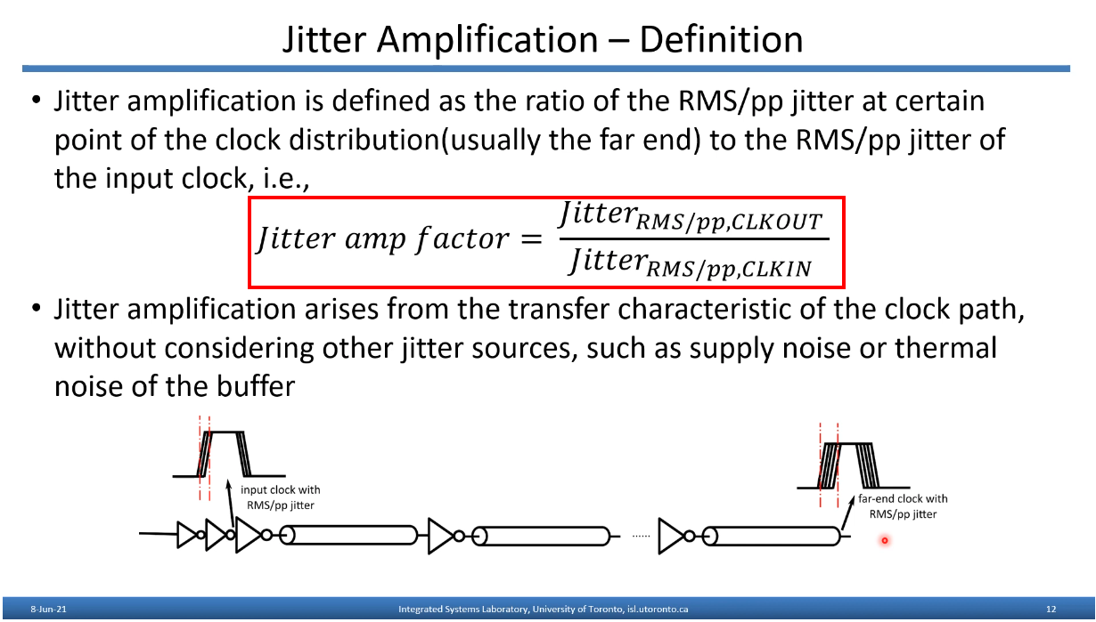
When impulsive jitter is injected into clock distribution circuits
(i.e., a small incremental time delay or advance applied to an
individual clock edge), it results in jitter in
multiple subsequent edges in the output clock
transient noise and
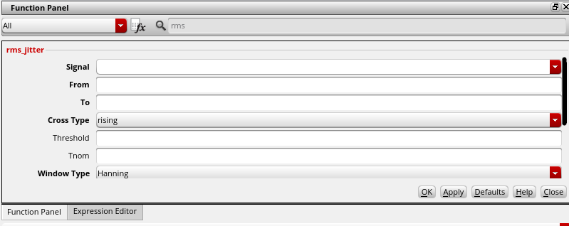
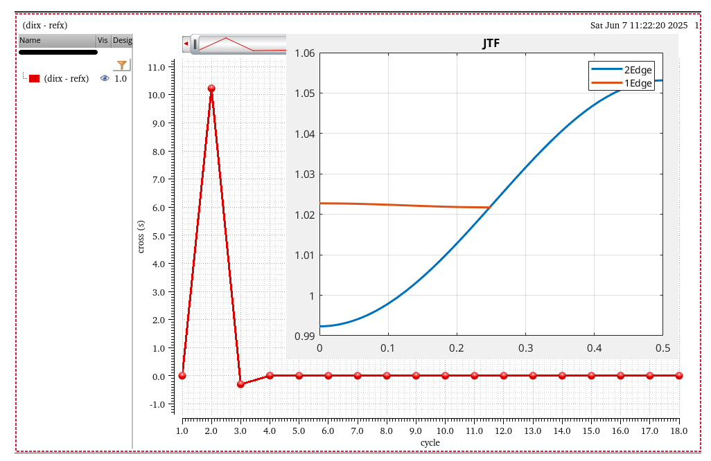
rms_jitter function
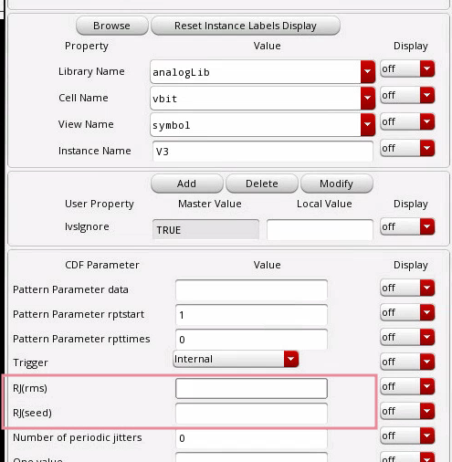
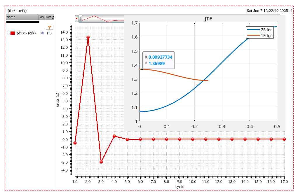
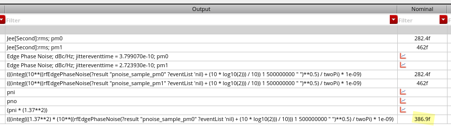
RJ(rms): single Edge or Both Edge?
RJ(seed): what is it?
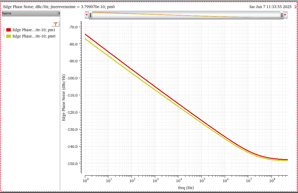
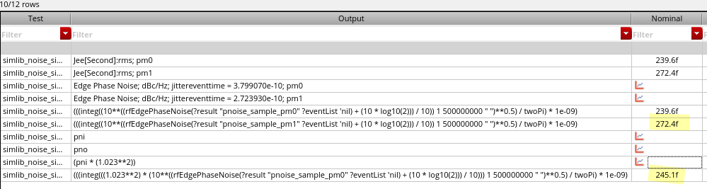
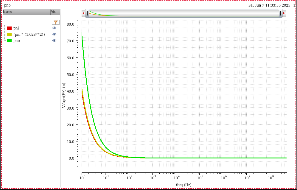
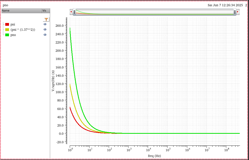
phase noise method
Directly compare the input phase noise and output phase noise, the
input waveform maybe is the PLL output or other clock distribution end
point
Jitter Impulse
Response & Jitter Transfer Function
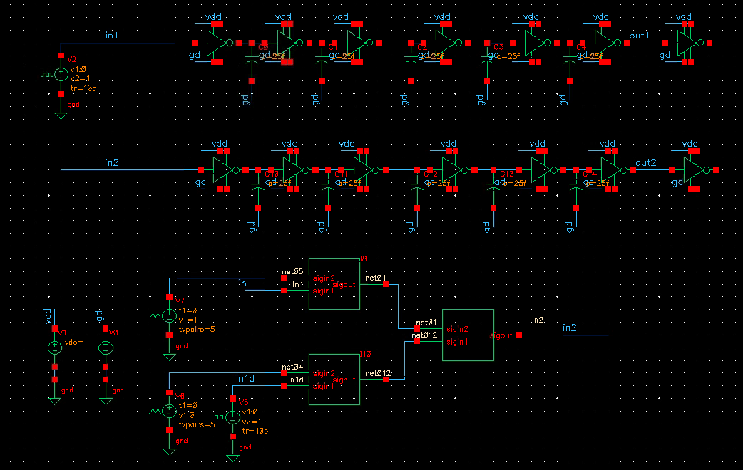
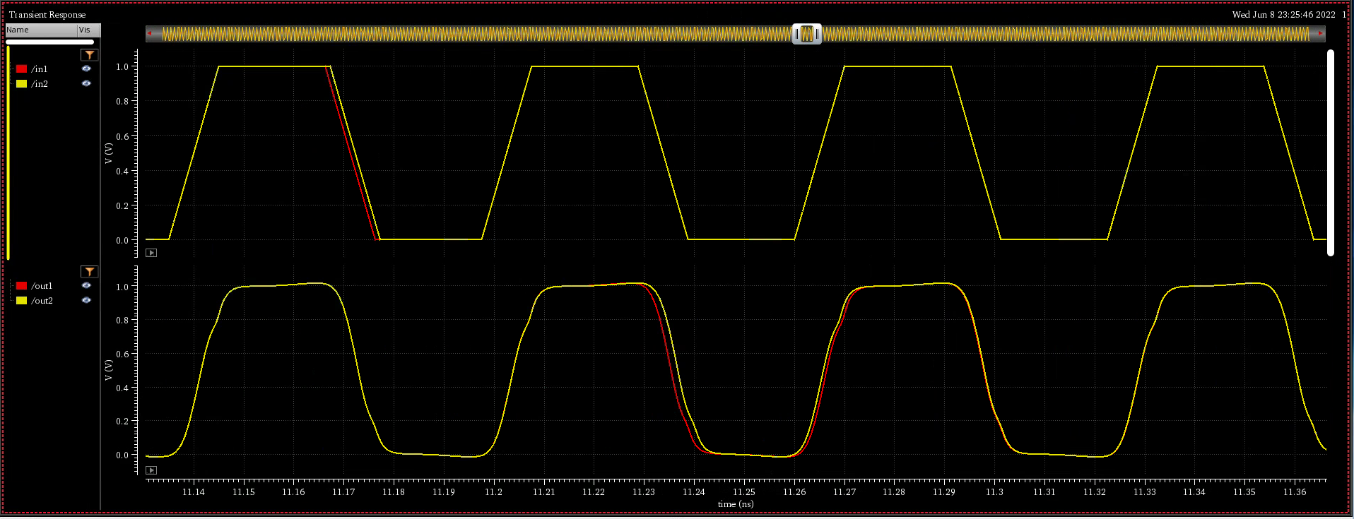
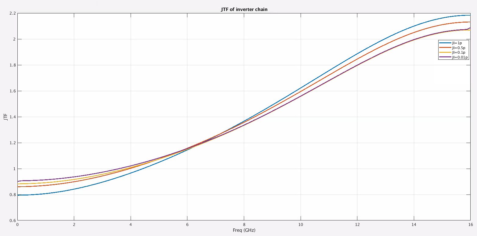
ji = 1e-12; % 1ps data = importdata('/path/to/jir.csv'); jo = data.data(:, 2); Ts = 31.25e-12; Fs = 1/Ts; jir = jo/ji; N = 2^(nextpow2(length(jir)-1)); Y = fft(jir, N); jtf = abs(Y(1:N/2+1)); freqs= Fs/N*(0:N/2); plot(feqs/1e9, jtf, 'linewidth', 2); grid on; xlabel('Freq (GHz)'); ylabel('JTF'); title('JTF of inverter chain');
JTF by step response
t0
t1
t2
t3
t4
t5
t6
t7
h0
h1
h2
h3
h4
h5
h6
h7
h0
h1
h2
h3
h4
h5
h6
h0
h1
h2
h3
h4
h5
h0
h1
h2
h3
h4
h0
h1
h2
h3
h0
h1
h2
h0
h1
h0
h0
h0+h1
h0+...h2
h0+...h3
h0+...h4
h0+...h5
h0+...h6
h0+...h7
For a unit-step input, the cumulative sum
h0+...+hn converges to 1,
ensuring a unity DC gain — \(X(e^{j0})=\sum_{n=-\infty}^{+\infty}x[n]e^{-j0
n}=\sum_{n=-\infty}^{+\infty}x[n]\)
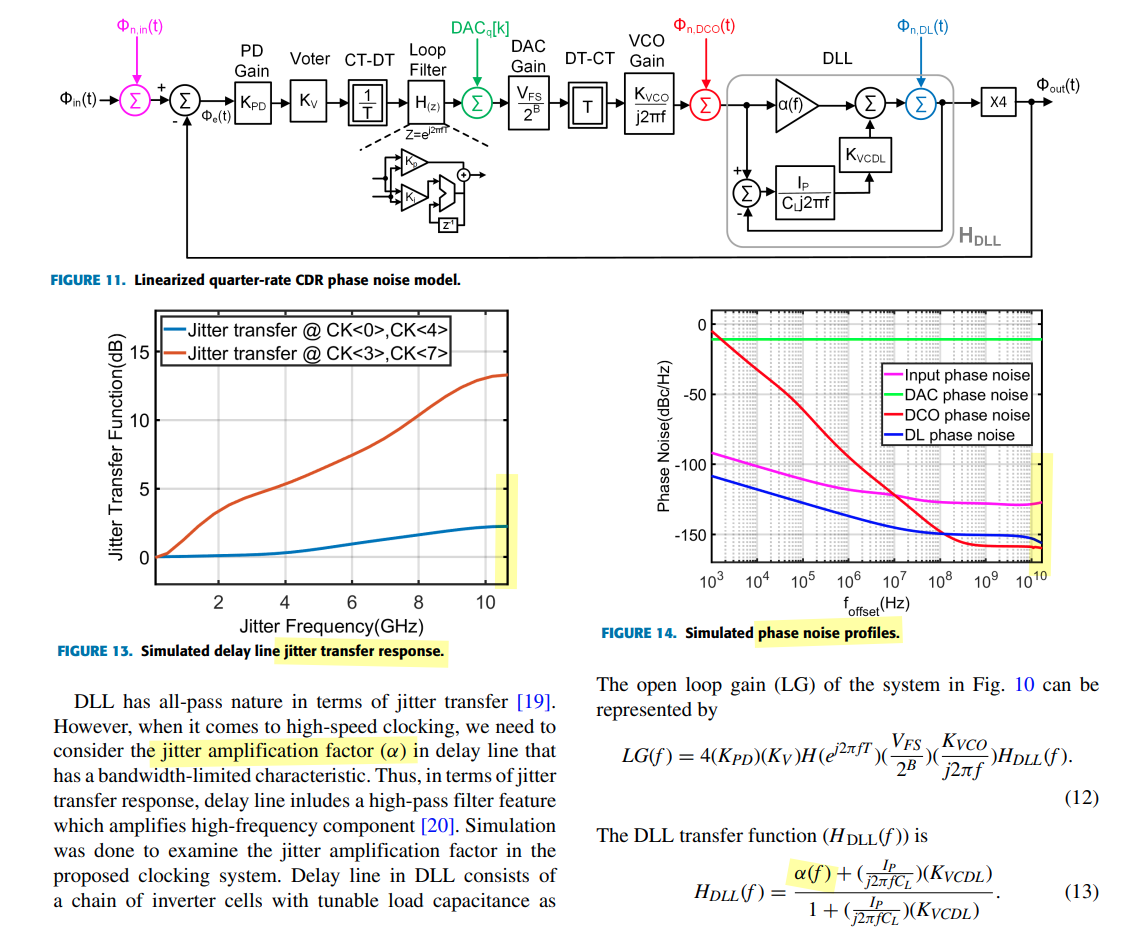
Four major noise sources are included in the modeling: Input noise,
DAC quantization noise (DAC QN), DCO random noise (DCO RN), and delay
line random noise (DL RN).
Rhee, W. (2020). Phase-locked frequency generation and clocking :
architectures and circuits for modern wireless and wireline
systems. The Institution of Engineering and Technology
Mathuranathan Viswanathan, Digital Modulations using Matlab : Build
Simulation Models from Scratch
Tony Chan Carusone, University of Toronto, Canada, 2022 CICC
Educational Sessions "Architectural Considerations in 100+ Gbps Wireline
Transceivers"
Ganesh Balamurugan and Naresh Shanbhag, "Modeling and mitigation of
jitter in multiGbps source-synchronous I/O links," Proceedings 21st
International Conference on Computer Design, San Jose, CA, USA,
2003, pp. 254-260, doi: 10.1109/ICCD.2003 [https://shanbhag.ece.illinois.edu/publications/ganesh-ICCD2203.pdf]
Balamurugan, G. & Casper, Bryan & Jaussi, James &
Mansuri, Mozhgan & O'Mahony, Frank & Kennedy, Joseph. (2009).
Modeling and Analysis of High-Speed I/O Links. Advanced Packaging, IEEE
Transactions on. [https://sci-hub.se/10.1109/TADVP.2008.2011366]
Jihwan Kim, ISSCC2019 F5: Design Techniques for a 112Gbs PAM-4
Transmitter
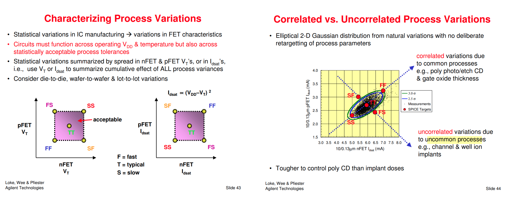
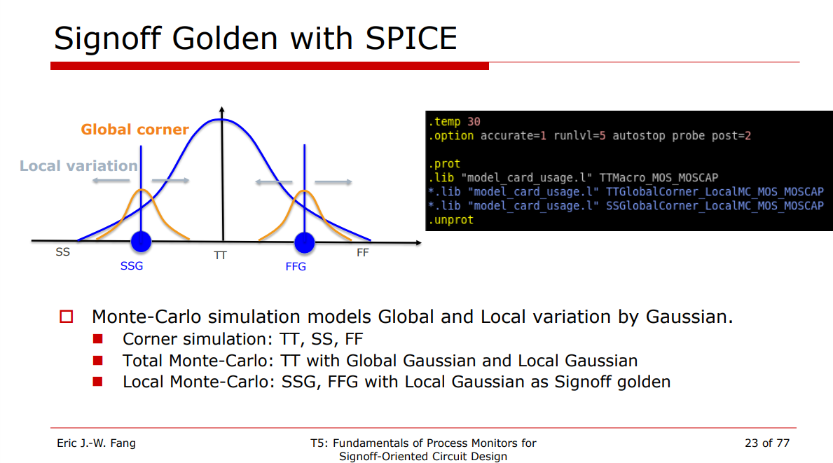
Local Monte-Carlo (SSG, FFG with Local Gaussian) as
Signoff golden
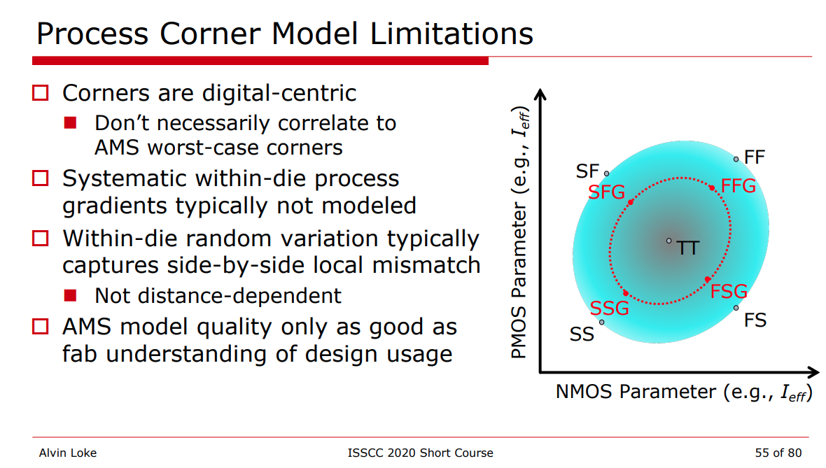
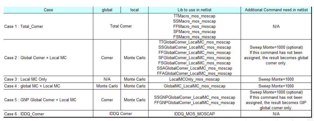
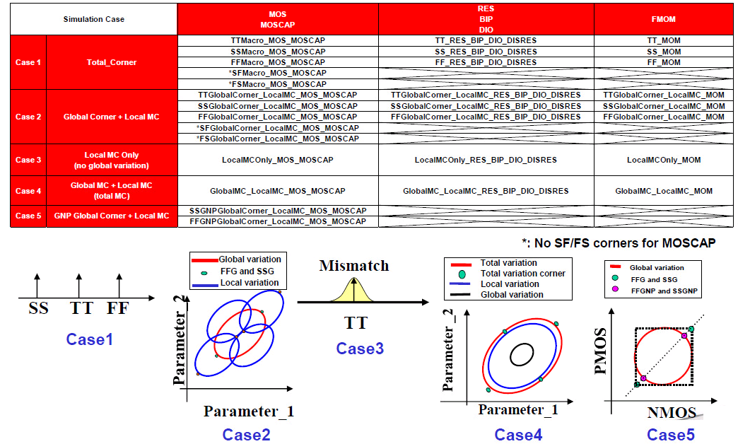
Process Corner Model
Limitations
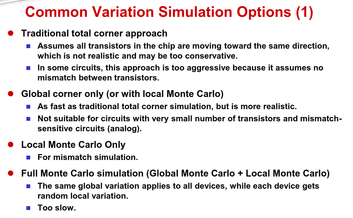
Variation section
Total corner (TT/SS/FF/SF/FS)
E.g. TTMacro_MOS_MOS_MOSCAP
Global Corner (TTG/SSG/FFG/SFG/FSG) + Local MC
E.g. TTGlobalCorner_LocalMC_MOS_MOSCAP
Local MC
E.g. LocalMCOnly_MOS_MOSCAP
Global MC + Local MC (Total MC)
GlobalMC_LocalMC_MOS_MOSCAP
SSGNP, FFGNP:
When N/P global correlation is weak (R^2=0.15), the corner of N/PMOS
balance circuit (e.g. inverter) can be tightened (3sigma ->
2.5sgma) due to the cancellation between NMOS
and PMOS
SSGNP, FFGNP usually used in Digital STA
Global variation validation with global
corner
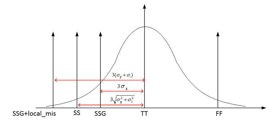
3-sigma of global MC simulation is aligned with
global corner
Total variation validation with total
corner
3-sigma of global MC + local MC (total) simulation
is aligned with total corner
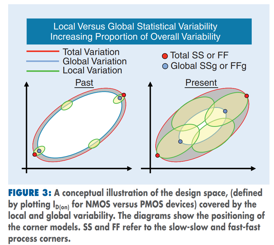
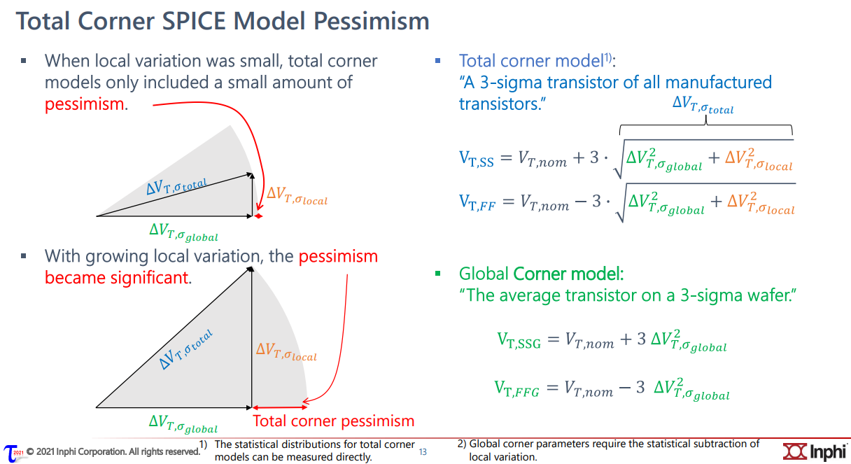
The "total corner" is representative of the maximum
device parameter variation including local device variation effects.
However, it is not a statistical corner.
The "global" corner is defined as the
"total" corner minus the impact of "local
variation"
Hence, if you were to examine simulation results for a parameter
using a "total" and "global" corner, you would find the range of
variation will be less with the "global" corner than with the "total"
corner.
The "global" corner is provided for use in statistical
simulations. Hence, when performing a Monte-Carlo simulation,
the "global" corner is selected - NOT the "total" corner.
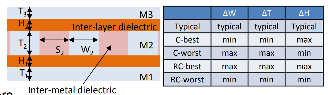
Metal width variation (\(\Delta
W\)), Metal thickness variation (\(\Delta T\)), IMD thickness variation (\(\Delta H\))
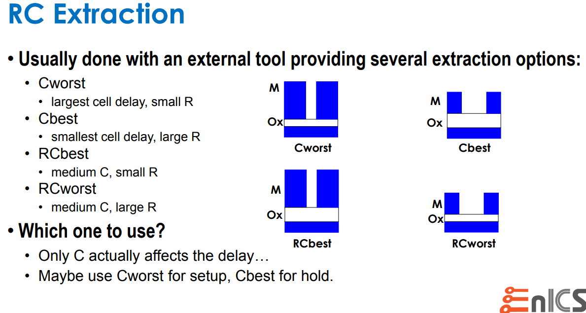
Capacitance Dominant: C-best, C-worst
Resistance Dominant: RC-best, RC-worst
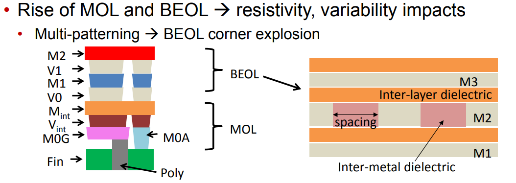
DPT effect
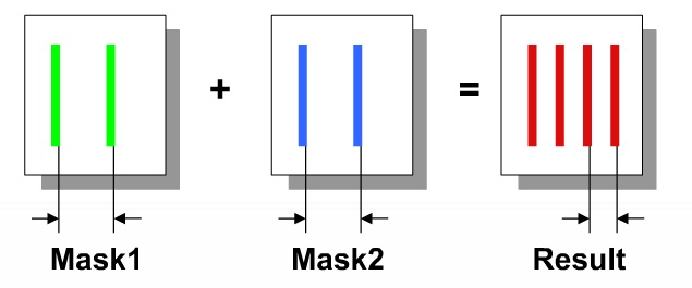
When using two masks per layer (Double Patterning Technology,
DPT) there is an issue of mask alignment where any
mis-alignment will cause layer spacing values to change, therefore
changing the parasitic coupling capacitance values.
Misalignment scale and direction are not deterministic facts:
coupling cap and total cap may be increased or decreased.
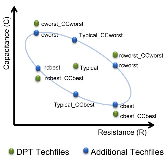
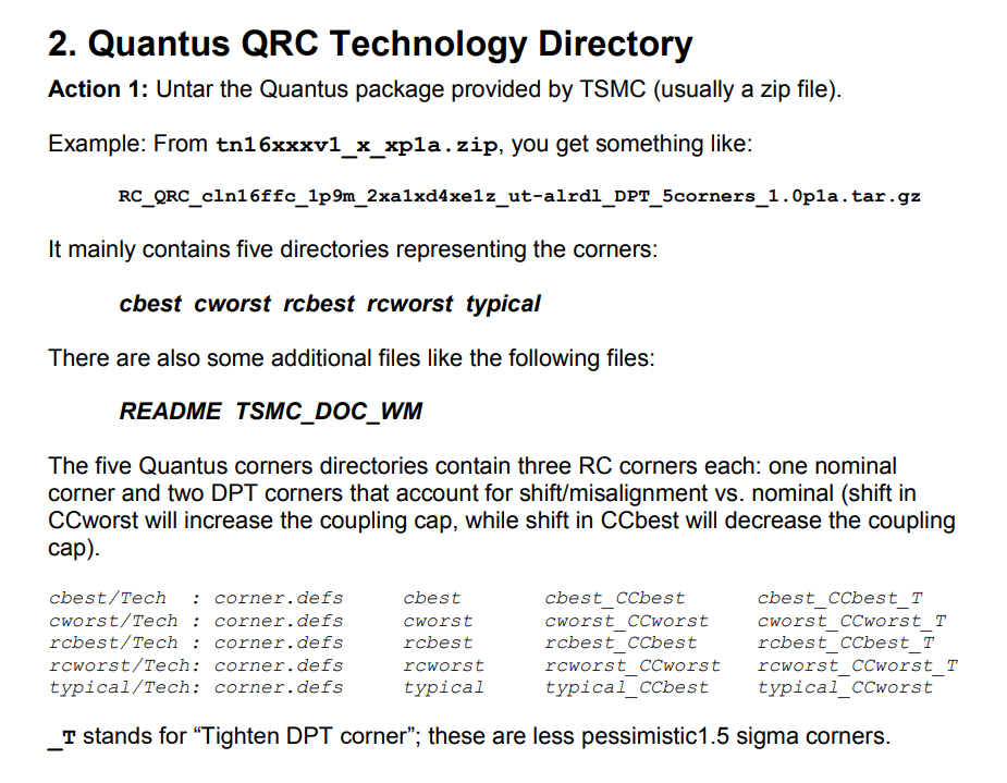
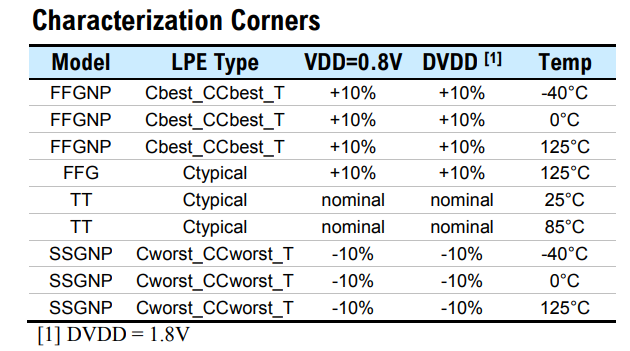
Five new corners are added in a DPT flow to account
for RC variations accurately:
sapced-dependent side-wall dielectric constant also affect coupling
cap
cworst_CCworst, cbest_CCbest, rcworst_CCworst, rcbest_CCbest and
typical
The others are for pre-color RC calculation purpose
_T stands for "Tighten DPT corner";
these are less pessimistic 1.5 sigma corners
Below table is caputre of Aragio's TSMC16: LVDS datasheet
BEOL corner
Spacing variation is implicitly defined by \(\Delta W_m\).
We denote the conductor width and thickness of the layer m
by \(W_m\) and \(T_m\), respectively.
Similarly, we denote the thickness of the layer's interlayer
dielectric (i.e., the distance between layer m and layer m +1) by \(H_m\)
C-based means worst and best caps
RC-based means worst and best R in adjustment
with C (RC product)
Based on experience, it was found that C-based
extraction provides worst and best case over RC for internal
timing paths because Capacitance dominates short
wire.
However, for large design, inter-block timing paths were often worst
with RC worst parasitic since R dominates for
long wires.
signoff corners for setup &
hold
reference
Process Variation
Eric J.-W. Fang, T5: Fundamentals of Process Monitors for
Signoff-Oriented Circuit Design, 2022 IEEE International Solid-State
Circuits Conference
Alvin Loke, Device and Physical Design Considerations for Circuits in
FinFET Technology, ISSCC 2020 Short Course
Radojcic, Riko, Dan Perry and Mark Nakamoto. “Design for
manufacturability for fabless manufactuers.” IEEE Solid-State
Circuits Magazine 1 (2009): n. pag.
T. -B. Chan, S. Dobre and A. B. Kahng, "Improved signoff methodology
with tightened BEOL corners," 2014 IEEE 32nd International Conference on
Computer Design (ICCD), Seoul, Korea (South), 2014, pp. 311-316, doi:
10.1109/ICCD.2014.6974699.
Chan, T. (2014). Mitigation of Variability and Reliability Margins in
IC Implementation /. UC San Diego. ProQuest ID:
Chan_ucsd_0033D_14269. Merritt ID: ark:/20775/bb52916761. Retrieved from
https://escholarship.org/uc/item/35r1m001
primary
clock, generated clock and virtual clock in SDC
primary clocks
Primary clocks should be created at input ports and output pins of
black boxes.
Never create clocks on hierarchy pins. Creating clocks on hierarchy
will cause problems when reading SDF. The net timing arc becomes
segmented at the hierarchy and PrimeTime will be unable to annotate the
net successfully.
generated clocks
Generated clocks are generally created for waveform modifications of
a primary clock (not including simple inversions). PrimeTime does not
simulate a design and thus will not derive internally
generated clocks automatically - these clocks must be created by the
user and applied as a constraint.
PrimeTime caculate source latency for generated clocks if primary
clock is propagated, otherwise its source latency is
zero.
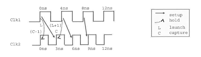
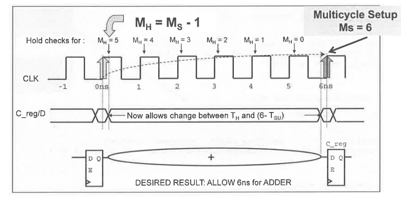
MH stands for Hold Multiplier, MS for Setup
Multiplier. The Setup multiplier counts up with increasing clock cycles,
the Hold Multiplier counts up with decreasing cycles. The origin (0) for
the Hold Multiplier is always at the Setup Multiplier - 1
position.
Reporting a
multicycle path with report_timing
1
report_timing -exceptions all -from *reg[26]/CP -to *reg/D
Timing Exceptions
If certain paths are not intended to operate
according to the default setup and hold behavior assumed by the
PrimeTime tool, you need to specify those paths as timing
exceptions. Otherwise, the tool might incorrectly report those paths as
having timing violations.
The PrimeTime tool lets you specify the following types of
exceptions:
False path – A path that is never sensitized due to the logic
configuration, expected data sequence, or operating mode.
Multicycle path – A path designed to take more than one clock cycle
from launch to capture.
Minimum or maximum delay path – A path that must meet a delay
constraint that you explicitly specify as a time value.
Error-[SV-LCM-PND] Package not defined ../sv/yapp_if.sv, 18 yapp_if, "yapp_pkg::" Package scope resolution failed. Token 'yapp_pkg' is not a package. Originating module 'yapp_if'. Move package definition before the use of the package.
place hw_top.svbefore or afteryapp_router.sv doesn't matter, the compiler (xrun, vcs)
can compile them successfully.
Conclusion
Always place package before DUT is preferred choice during
compiling.
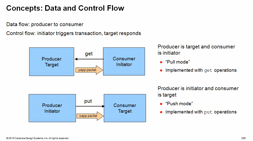
Transaction Level Modeling
(TLM)
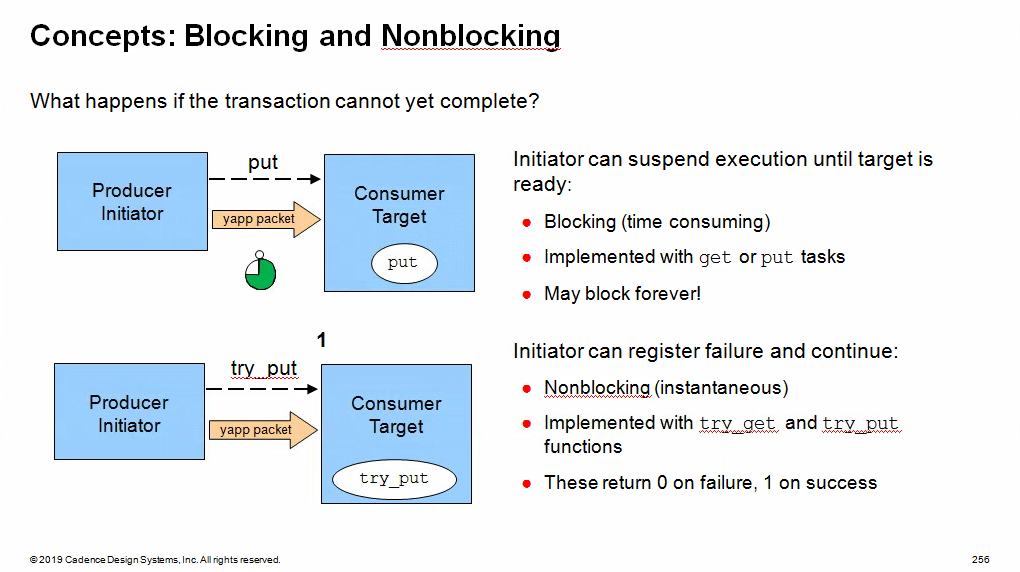
Blocking methods are defined with
get() or put()tasks to allow
them to consume time
Non-blocking methods are defined with
try_get() or try_put()functions as they execute in zero time
Uni-Directional TLM
Methods Reference
Method
Description
Syntax
put()
Blocking put
virtual task put(iput TR t);
try_put()
Nonblocking put -return 1 if successful -return 0 if
not
virtual function bit try_put(input TR t);
can_put()
Nonblocking test put -return 1 if put would be
successful -return 0 if not
virtual function bit can_put();
get()
Blocking get
virtual task get(output TR t);
try_get()
Nonblocking get -return 1 if successful -return 0 if
not
virtual function bit try_get(output TR t);
can_get()
Nonblocking test get -return 1 if get would be
successful -return 0 if not
virtual function bit can_get();
peek()
Blocking peek
virtual task peek(output TR t);
try_peek()
Nonblocking peek -return 1 if successful -return 0 if
not
virtual function bit try_peek(output TR t);
can_peek
Nonblocking test peek -return 1 if peek would be
successful -return 0 if not
virtual function bit can_peek();
The peek() methods are similarly to the
get() methods, but copy the transaction
instead of removing it. The transaction is not
consumed, and a subsequent get or peek
operation will return the same transaction
Selected Connector and
Method Options
put
try_put
can_put
get
try_get
can_get
peek
try_peed
can_peek
uvm_put_*
✓
✓
✓
uvm_blocking_put_*
✓
uvm_nonblocking_put_*
✓
✓
uvm_get_*
✓
✓
✓
uvm_blocking_get_*
✓
uvm_nonblocking_get_*
✓
✓
uvm_get_peek_*
✓
✓
✓
✓
✓
✓
uvm_blocking_get_peek_*
✓
✓
uvm_nonblocking_get_peek_*
✓
✓
✓
✓
in the connectors above, * can be replaced by
port, imp, or export
All the methods for a specific connector type MUST
be implemented. If you define an uvm_put connection between
two compoents, then the component with the uvm_put_imp
object must provide implementations of ALL three put
methods, put, try_put and
can_put, even if these methods are not explicitly
called
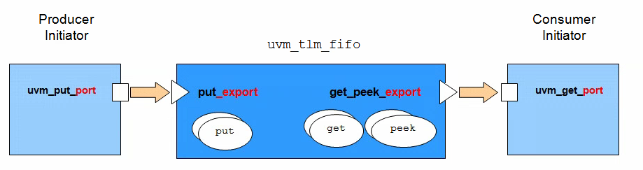
TLM FIFO
The TLM FIFO is a FIFO component wrapped in get and
putimp connectors. This has the benefit of
data storage as well as providing implementations of the communication
methods. Components connected to the TLM FIFO are in control of data
transfer and can simply defined port connectors to initiate read and
write operations on the FIFO
uvm_tlm_fifo
The TLM FIFO object is effectively a FIFO component instantiated
between and connected to two components. The FIFO contains
imp connectors for the standard TLM put and
get/peek interfaces, therefore the user does
not have to defineimp ports or communication methods and
the FIRO takes care of data storage
The advantages are:
The user does not need to define communication methods or
imp connectors
The FIFO provides data storage between the write
(put) and read
(get/peek) components
There are a number of built-in methods for checking FIFO status
The disadvantages are:
The user must now initiate both sides of the transfer (both
get/peek and put) to complete the
transaction
Two connections must be made (both sides of the FIFO) rather than
one
The put_export and get_peek_export
connection objects have alternatives which provide subsets of the full
connector. For example, blocking_put_export and
nonblocking_put_export can replace put_export.
blocking_get_export, nonblocking_get_export
and get_export (as well as others) can replace
get_peek_export.
built-in methods
Method
Description
Syntax
new
Standard component constructor with an additional third argument,
size, which sets the maximum FIFO size. Default size is 1.
A size of 0 is an unbounded FIFO
function new(string name, uvm_component parent=null, int size=1);
size
Return size of FIFO. 0 indicates unbounded
FIFO
virtual function int size()
used
Return number of entries written to the FIFO
virtual function int used();
is_empty
Return 1 if used() is 0, otherwise
0
virtual function bit is empty();
is_full
Return 1 if used() is equal to size,
otherwise 0
virtual function bit is_full()
flush
Delete all entries from the FIFO, upon which used() is
0 and is_empty() is
1
virtual funciton void flush();
1 2 3
class uvm_tlm_fifo #(type T=int) extends uvm_tlm_fifo_base #(T); ... endclass
virtualclass uvm_tlm_fifo_base #(type T=int)extends uvm_component; uvm_put_imp #(T, this_type) put_export; uvm_get_peek_imp #(T, this_type) get_peek_export; uvm_analysis_port #(T) put_ap; uvm_analysis_port #(T) get_ap; // The following are aliases to the above put_export uvm_put_imp #(T, this_type) blocking_put_export; uvm_put_imp #(T, this_type) nonblocking_put_export; // The following are all aliased to the above get_peek_export, which provides // the superset of these interfaces. uvm_get_peek_imp #(T, this_type) blocking_get_export; uvm_get_peek_imp #(T, this_type) nonblocking_get_export; uvm_get_peek_imp #(T, this_type) get_export; uvm_get_peek_imp #(T, this_type) blocking_peek_export; uvm_get_peek_imp #(T, this_type) nonblocking_peek_export; uvm_get_peek_imp #(T, this_type) peek_export; uvm_get_peek_imp #(T, this_type) blocking_get_peek_export; uvm_get_peek_imp #(T, this_type) nonblocking_get_peek_export; functionnew(string name, uvm_component parent = null); super.new(name, parent); put_export = new("put_export", this); blocking_put_export = put_export; nonblocking_put_export = put_export; get_peek_export = new("get_peek_export", this); blocking_get_peek_export = get_peek_export; nonblocking_get_peek_export = get_peek_export; blocking_get_export = get_peek_export; nonblocking_get_export = get_peek_export; get_export = get_peek_export; blocking_peek_export = get_peek_export; nonblocking_peek_export = get_peek_export; peek_export = get_peek_export; put_ap = new("put_ap", this); get_ap = new("get_ap", this); endfunction
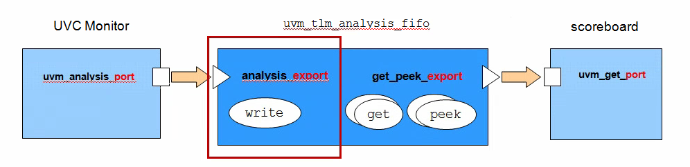
Analysis FIFO
uvm_tlm_analysis_fifo
uvm_tlm_analysis_fifo is a specialization of
uvm_tlm_fifo
Intended to buffer write transactions between the UVC monitor
analysis port and scoreboard
It has the following characteristics:
Unbounded (size=0)
analysis_export connector replaces
put_export
Support the analysis write method
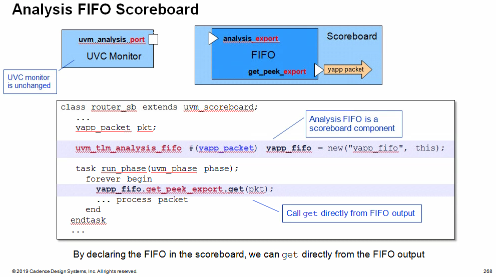
By declaring the FIFO in the scoreboard, we can get
directly from the FIFO output.
However the write side connection of the FIFO to the interface UVC
monitor analysis port must be made (usually) in the testbench which has
visibility of both UVC and scoreboard components. The connection is made
using a connect method call inside the connect phase method
class uvm_tlm_analysis_fifo #(type T = int) extends uvm_tlm_fifo #(T);
// Port: analysis_export #(T) // // The analysis_export provides the write method to all connected analysis // ports and parent exports: // //| function void write (T t) // // Access via ports bound to this export is the normal mechanism for writing // to an analysis FIFO. // See write method of <uvm_tlm_if_base #(T1,T2)> for more information.
// Function: new // // This is the standard uvm_component constructor. ~name~ is the local name // of this component. The ~parent~ should be left unspecified when this // component is instantiated in statically elaborated constructs and must be // specified when this component is a child of another UVM component.
functionnew(string name , uvm_component parent = null); super.new(name, parent, 0); // analysis fifo must be unbounded analysis_export = new("analysis_export", this); endfunction
functionvoid write(input T t); void'(this.try_put(t)); // unbounded => must succeed endfunction
endclass
Analysis Port Broadcast
Analysis ports can (uniquely) be connected to any number of
imp connectors, including zero
The analysis port in component yapp_monitor will be
connected to both monitor_one and monitor_two
components. Each of the receiving components has an analysis imp
object and a write communication method declared. The write method
must have the same signature - i.e., they must be void functions called
write with a single input argument of type yapp_packet, but
their implementations can be completely different.
When the send_yapp port is connected to both
mone_in and mtwo_in imps, then a single write call
from yapp_monitor executes both write implementations in
monitor_one and monitor_two
For non-analysis connections
the TLM object must be connected to a single destination only, i.e.,
each non-analysis object has exactly one connect call.
An object may be used multiple times as the argument to a
connect, but exactly once as the caller. This is called
many-to-one connection. For example, many ports can be
connected to a one imp connector
For analysis connections
a TLM object can be connected to any number of destinations i.e.,
one analysis object can call connect many times. This is called
one-to-many connection. For example, one port can be
connected to many imp connectors. one-to-many is only
allowed for analysis connections. An analysis connection can also
NOT call connect. An unconnected TLM object is also only
allowed for analysis connections
Bi-Directional TLM
Transport Connection
Connector syntax
1 2 3
uvm_blocking_transport_XXX #(type REA, type RSP) uvm_nonblocking_transport_XXX #(type REQ, type RSP) uvm_transport_XXX #(type REQ, type RSP)
FIFO/analysis FIFOs do not perform any cloning on input transactions.
Therefore, you will need to check that the UVC monitors collect every
transaction into a different instance to avoid overwriting data in the
FIFOs
class uvm_reg_map extends uvm_object; // Function: add_submap // // Add an address map // // Add the specified address map instance to this address map. // The address map is located at the specified base address. // The number of consecutive physical addresses occupied by the submap // depends on the number of bytes in the physical interface // that corresponds to the submap, // the number of addresses used in the submap and // the number of bytes in the // physical interface corresponding to this address map. // // An address map may be added to multiple address maps // if it is accessible from multiple physical interfaces. // An address map may only be added to an address map // in the grand-parent block of the address submap. // externvirtualfunctionvoid add_submap (uvm_reg_map child_map, uvm_reg_addr_t offset);
// Function: add_mem // // Add a memory // // Add the specified memory instance to this address map. // The memory is located at the specified base address and has the // specified access rights ("RW", "RO" or "WO"). // The number of consecutive physical addresses occupied by the memory // depends on the width and size of the memory and the number of bytes in the // physical interface corresponding to this address map. // // If ~unmapped~ is TRUE, the memory does not occupy any // physical addresses and the base address is ignored. // Unmapped memories require a user-defined ~frontdoor~ to be specified. // // A memory may be added to multiple address maps // if it is accessible from multiple physical interfaces. // A memory may only be added to an address map whose parent block // is the same as the memory's parent block. // externvirtualfunctionvoid add_mem (uvm_mem mem, uvm_reg_addr_t offset, string rights = "RW", bit unmapped=0, uvm_reg_frontdoor frontdoor=null);
The generic register item is implemented as a struct in order to
minimise the amount of memory resource it uses. The struct is defined as
type uvm_reg_bus_op and this contains 6 fields:
Property
Type
Comment/Description
addr
uvm_reg_addr_t
Address field, defaults to 64 bits
data
uvm_reg_data_t
Read or write data, defaults to 64 bits
kind
uvm_access_e
UVM_READ or UVM_WRITE
n_bits
unsigned int
Number of bits being transferred
byte_en
uvm_reg_byte_en_t
Byte enable
status
uvm_status_e
UVM_IS_OK, UVM_IS_X, UVM_NOT_OK
1 2 3 4 5 6 7 8 9
typedefstruct { uvm_access_e kind; // Kind of access: READ or WRITE. uvm_reg_addr_t addr; // The bus address. uvm_reg_data_t data; // The data to write. // The number of bits of <uvm_reg_item::value> being transferred by this transaction. int n_bits; uvm_reg_byte_en_t byte_en; // Enables for the byte lanes on the bus. uvm_status_e status; // The result of the transaction: UVM_IS_OK, UVM_HAS_X, UVM_NOT_OK. } uvm_reg_bus_op;
The register class contains a build method which is used
to create and configure the
fields.
this build method is not called by the UVM
build_phase, since the register is an
uvm_object rather than an uvm_component
1 2 3 4 5 6
// // uvm_reg constructor prototype: // functionnew (string name="", // Register name intunsigned n_bits, // Register width in bits int has_coverage); // Coverage model supported by the register
As shown above, Register width is 32 same with the
bus width, lower 14 bit is configured.
RTL
1 2
`define SPI_CTRL_BIT_NB 14 reg [`SPI_CTRL_BIT_NB-1:0] ctrl; // Control and status register
Register Maps
Two purpose of the register map
provide information on the offset of the registers, memories and/or
register blocks
identify bus agent based sequences to be executed ???
There can be several register maps within a block, each one can
specify a different address map and a different
target bus agent
register map has to be created which the register
block using the create_map method
1 2 3 4 5 6 7 8 9 10 11 12 13
// // Prototype for the create_map method // function uvm_reg_map create_map(string name, // Name of the map handle uvm_reg_addr_t base_addr, // The maps base address intunsigned n_bytes, // Map access width in bytes uvm_endianness_e endian, // The endianess of the map bit byte_addressing=1); // Whether byte_addressing is supported // // Example: // AHB_map = create_map("AHB_map", 'h0, 4, UVM_LITTLE_ENDIAN);
The n_bytes parameter is the word size (bus
width) of the bus to which the map is associated. If a register's width
exceeds the bus width, more than one bus access is needed to read and
write that register over that bus.
he byte_addressing argument affects how the address is
incremented in these consecutive accesses. For example, if
n_bytes=4 and byte_addressing=0, then an access to a
register that is 64-bits wide and at offset 0 will result in two bus
accesses at addresses 0 and 1. With byte_addressing=1, that
same access will result in two bus accesses at addresses 0 and 4.
The default for byte_addressing is
1
The first map to be created within a register
block is assigned to the default_map member of the
register block
Register Adapter
uvm_reg_adapter
Methods
Description
reg2bus
Overload to convert generic register access items to target bus
agent sequence items
bus2reg
Overload to convert target bus sequence items to register model
items
Properties (Of type bit)
Description
supports_byte_enable
Set to 1 if the target bus and the target bus agent supports byte
enables, else set to 0
provides_responses
Set to 1 if the target agent driver sends separate response
sequence_items that require response handling
The provides_responses bit should be set if the
agent driver returns a separate response item (i.e.
put(response), or item_done(response)) from
its request item
Prediction
the update, or prediction, of the register model content can occur
using one of three models
Auto Prediction
This mode of operation is the simplest to implement, but suffers from
the drawback that it can only keep the register model up to date with
the transfers that it initiates. If any other sequences
directly access the target sequencer to update register content, or if
there are register accesses from other DUT interfaces, then the register
model will not be updated.
// Gets the auto-predict mode setting for this map. functionbit uvm_reg_map::get_auto_predict(); return m_auto_predict; endfunction
// Function: set_auto_predict
//
// Sets the auto-predict mode for his map.
//
// When on is TRUE,
// the register model will automatically update its
mirror (what it thinks should be in the DUT)
immediately after any bus read or write operation via this map.
Before a uvm_reg::write
// or uvm_reg::read operation returns, the register's
uvm_reg::predict method is called to update
the mirrored value in the register.
//
// When on is FALSE, bus reads and writes via
this map do not
// automatically update the mirror. For real-time updates to the
mirror
// in this mode, you connect a uvm_reg_predictor
instance to the bus
// monitor. The predictor takes observed bus transactions from
the
// bus monitor, looks up the associated uvm_reg register
given
// the address, then calls that register's
uvm_reg::predict method.
// While more complex, this mode will capture all register
read/write
// activity, including that not directly descendant from calls to
// uvm_reg::write and uvm_reg::read.
//
// By default, auto-prediction is turned off.
//
The register model content is updated based on the register accesses
it initiates
Explicit Prediction
(Recommended Approach)
Explicit prediction is the default mode of
prediction
The register model content is updated via the predictor
component based on all observed bus transactions, ensuring that
register accesses made without the register model are mirrored
correctly. The predictor looks up the accessed register by address then
calls its predict() method
if (m_is_busy && kind == UVM_PREDICT_DIRECT) begin `uvm_warning("RegModel", {"Trying to predict value of register '", get_full_name(),"' while it is being accessed"}) rw.status = UVM_NOT_OK; return; end foreach (m_fields[i]) begin rw.value[0] = (reg_value >> m_fields[i].get_lsb_pos()) & ((1 << m_fields[i].get_n_bits())-1); m_fields[i].do_predict(rw, kind, be>>(m_fields[i].get_lsb_pos()/8)); end
UVM_PREDICT_DIRECT: begin if (m_parent.is_busy()) begin `uvm_warning("RegModel", {"Trying to predict value of field '", get_name(),"' while register '",m_parent.get_full_name(), "' is being accessed"}) rw.status = UVM_NOT_OK; end end endcase
// update the mirror with predicted value m_mirrored = field_val; m_desired = field_val; this.value = field_val;
endfunction: do_predict
uvm_access_e
1 2 3 4 5 6 7 8 9 10 11 12 13
// Enum: uvm_access_e // // Type of operation begin performed // // UVM_READ - Read operation // UVM_WRITE - Write operation // typedefenum { UVM_READ, UVM_WRITE, UVM_BURST_READ, UVM_BURST_WRITE } uvm_access_e;
uvm_predict_e
1 2 3 4 5 6 7 8 9 10 11 12 13
// Enum: uvm_predict_e // // How the mirror is to be updated // // UVM_PREDICT_DIRECT - Predicted value is as-is // UVM_PREDICT_READ - Predict based on the specified value having been read // UVM_PREDICT_WRITE - Predict based on the specified value having been written // typedefenum { UVM_PREDICT_DIRECT, UVM_PREDICT_READ, UVM_PREDICT_WRITE } uvm_predict_e;
uvm_path_e
1 2 3 4 5 6 7 8 9 10 11 12 13 14 15 16
// Enum: uvm_path_e // // Path used for register operation // // UVM_FRONTDOOR - Use the front door // UVM_BACKDOOR - Use the back door // UVM_PREDICT - Operation derived from observations by a bus monitor via // the <uvm_reg_predictor> class. // UVM_DEFAULT_PATH - Operation specified by the context // typedefenum { UVM_FRONTDOOR, UVM_BACKDOOR, UVM_PREDICT, UVM_DEFAULT_PATH } uvm_path_e;
whether a register field can be read or written depends on both the
field's configured access policy and the register's rights in the map
being used to access the field
If a back-door access path is used, the effect of writing the
register through a physical access is mimicked. For example,
read-only bits in the registers will
not be written.
The mirrored value will be updated using the
uvm_reg::predict() method.
If a back-door access path is used, the effect of reading the
register through a physical access is mimicked. For example,
clear-on-read bits in the registers will be set to
zero.
The mirrored value will be updated using the
uvm_reg::predict() method.
Sample the value in the DUT register corresponding to this
abstraction class instance using a back-door access.
The register value is sampled, not modified.
Uses the HDL path for the design abstraction specified by
kind.
The mirrored value will be updated using the
uvm_reg::predict() method.
Read the register and optionally compared the readback
value with the current mirrored value if
check is UVM_CHECK.
The mirrored value will be updated using the
uvm_reg::predict() method based on the readback
value.
The mirroring can be performed using the physical interfaces
(frontdoor) or uvm_reg::peek() (backdoor).
If the register contains write-only fields,
their content is mirrored and optionally checked only if a
UVM_BACKDOOR access path is used to read the
register.
Write this register if the DUT register is out-of-date with the
desired/mirrored value in the abstraction class, as determined by the
uvm_reg::needs_update() method.
The update can be performed using the using the physical interfaces
(frontdoor) or uvm_reg::poke() (backdoor) access.
functionbit uvm_reg::needs_update(); needs_update = 0; foreach (m_fields[i]) begin if (m_fields[i].needs_update()) begin return1; end end endfunction: needs_update
// Concatenate the write-to-update values from each field // Fields are stored in LSB or MSB order upd = 0; foreach (m_fields[i]) upd |= m_fields[i].XupdateX() << m_fields[i].get_lsb_pos();
Update the mirrored and desired value for this
register.
Predict the mirror (and desired) value of the fields in the register
based on the specified observed value on a specified
address map, or based on a calculated value.
if (rw.status ==UVM_IS_OK ) rw.status = UVM_IS_OK;
if (m_is_busy && kind == UVM_PREDICT_DIRECT) begin `uvm_warning("RegModel", {"Trying to predict value of register '", get_full_name(),"' while it is being accessed"}) rw.status = UVM_NOT_OK; return; end
foreach (m_fields[i]) begin rw.value[0] = (reg_value >> m_fields[i].get_lsb_pos()) & ((1 << m_fields[i].get_n_bits())-1); m_fields[i].do_predict(rw, kind, be>>(m_fields[i].get_lsb_pos()/8)); end
UVM_PREDICT_DIRECT: begin if (m_parent.is_busy()) begin `uvm_warning("RegModel", {"Trying to predict value of field '", get_name(),"' while register '",m_parent.get_full_name(), "' is being accessed"}) rw.status = UVM_NOT_OK; end end endcase
// update the mirror with predicted value m_mirrored = field_val; m_desired = field_val; this.value = field_val;
Resetting a register model sets the mirror to the reset value
specified in the model
uvm_reg::reset
1 2 3 4 5 6 7 8 9 10
functionvoid uvm_reg::reset(string kind = "HARD"); foreach (m_fields[i]) m_fields[i].reset(kind); // Put back a key in the semaphore if it is checked out // in case a thread was killed during an operation void'(m_atomic.try_get(1)); m_atomic.put(1); m_process = null; Xset_busyX(0); endfunction: reset
m_mirrored = m_reset[kind]; m_desired = m_mirrored; value = m_mirrored;
if (kind == "HARD") m_written = 0;
endfunction: reset
uvm_reg_field::randomize
uvm_reg_field::pre_randomize()
Update the only publicly known property value with the
current desired value so it can be used as a state
variable should the rand_mode of the field be turned
off.
value is m_desired if
rand_mode is off.
1 2 3
functionvoid uvm_reg_field::pre_randomize(); value = m_desired; endfunction: pre_randomize
// Enum: uvm_predict_e // // How the mirror is to be updated // // UVM_PREDICT_DIRECT - Predicted value is as-is // UVM_PREDICT_READ - Predict based on the specified value having been read // UVM_PREDICT_WRITE - Predict based on the specified value having been written // typedefenum { UVM_PREDICT_DIRECT, UVM_PREDICT_READ, UVM_PREDICT_WRITE } uvm_predict_e;
UVM REG RALF & IP-XACT
UVM Register Abstraction Layer Generator User Guide, S-2021.09-SP1,
December 2021
class ral_reg_CTRL extends uvm_reg; class ral_reg_STAT extends uvm_reg; class ral_reg_HTIM extends uvm_reg; class ral_reg_VTIM extends uvm_reg; class ral_reg_C1CR extends uvm_reg; class ral_mem_CLUT1 extends uvm_mem; class ral_block_vga_lcd extends uvm_reg_block;
ralgen command
1
ralgen -uvm -t dut_regmodel0 vga_lcd_env.ralf
BYTE or HALFWORD access
User is verifying 32 bit registers and the design also allows the
BYTE (8 bits) and HALFWORD (16 bits) accesses.
this is achieved by setting the bit_addressing=0
field in the uvm_reg_block::create_map function.
Using create_map in uvm_reg_block, you can
change the type of addressing scheme you want to use; namely BYTE or
HALFWORD.
this.maps[map] = 1; if (maps.num() == 1) default_map = map;
return map; endfunction
uvm_reg_map::add_reg
The register is located at the specified address offset from
this maps configured base address.
The number of consecutive physical addresses occupied by the register
depends on the width of the register and the number of bytes in the
physical interface corresponding to this address map.
If unmapped is TRUE, the register does not occupy any
physical addresses and the base address is ignored. Unmapped registers
require a user-defined frontdoor to be specified.
functionvoid uvm_reg_map::add_reg(uvm_reg rg, uvm_reg_addr_t offset, string rights = "RW", bit unmapped=0, uvm_reg_frontdoor frontdoor=null);
if (m_regs_info.exists(rg)) begin `uvm_error("RegModel", {"Register '",rg.get_name(), "' has already been added to map '",get_name(),"'"}) return; end
if (rg.get_parent() != get_parent()) begin `uvm_error("RegModel", {"Register '",rg.get_full_name(),"' may not be added to address map '", get_full_name(),"' : they are not in the same block"}) return; end rg.add_map(this);
begin uvm_reg_map_info info = new; info.offset = offset; info.rights = rights; info.unmapped = unmapped; info.frontdoor = frontdoor; m_regs_info[rg] = info; end endfunction
a register has an addressOffset that describes the
location of the register expressed in addressUnitBits as
offset to the starting address of the containing
addressBlock or the containing
registerFile
addressUnitBits
The addressUnitBits element describes the number of bits
of an address increment between two consecutive addressable
units in the addressSpace. If
addressUnitBits is not described, then its value
defaults to 8, indicating a
byte-addressableaddressSpace
block
memory
Global Handles in UVM
Mechanism in UVM-1.1
1 2 3 4 5
functionvoid test_base::start_of_simulation_phase(uvm_phase phase); super.start_of_simulation_phase(phase); uvm_top.print_topology(); // Will not compile in UVM-1.2 factory.print(); // Will not compile in UVM-1.2 endfunction
Global handles uvm_top and factory in uvm_pkg have been removed in
UVM-1.2 and later
Mechanism in UVM-1.1 and
UVM-1.2
Call the get() method of the class to retrieve the
singleton handle.
1 2 3 4 5
functionvoid test_base::start_of_simulation_phase(uvm_phase phase); super.start_of_simulation_phase(phase); uvm_root::get().print_topology(); // Works in UVM-1.1 & UVM-1.2 uvm_factory::get().print(); // Works in UVM-1.1 & UVM-1.2 endfunction
uvm_coreservice_t is the uvm-1.2 mechanism for
accessing all the central UVM services such as
uvm_root,uvm_factory,
uvm_report_server, etc.
1 2 3 4 5 6 7
// Using the uvm_coreservice_t: uvm_coreservice_t cs; uvm_factory f; uvm_root top; cs = uvm_coreservice_t::get(); f = cs.get_factory(); top = cs.get_root();
As you can see , the uvm_config_db::set is after the
factory type_id::create, but receive_value
is still 100, I believe that build_phase
of upper hierarchy finish first before create lower components.
But the recommendation in literature and many web is place
uvm_config_db::set before create
// YAPP Interface to the DUT yapp_if in0(clock, reset); // reset will now be generated by the Clock and Reset UVC // input: clock; output: reset, run_clock, clock_period clock_and_reset_if clk_rst_if(.clock(clock), .reset(reset), .run_clock(run_clock), .clock_period(clock_period)); hbus_if hif(.clock(clock), .reset(reset));
imp and port connectors are sufficient for
modeling most connections, but there is third connector,
export, which is used exclusively in hierarchical
connections.
Normally hierarchical routing is not required. A port on
an UVC monitor can be connected directly to an imp in a
scoreboard by specifying full hierarchical pathname (e.g.,
env.agent.monitor.analysis_port). The structure of an UVC is fixed and
so the user knows to look in the monitor component for the analysis
ports.
However the internal hierarchy of a module UVC is more arbitrary, and
it may be convenient to route all the module UVC connectors to the top
level to allow use without knowledge of the internal structure.
On the initiator side
ports are routed up the hierarchy via other port instances
On the target side
only the component which defines the communication method is allowed
to have an imp instance. So we need a third object to route
connections up the target side hierarchy - export
The hierarchical route must be connected at each level in the
direction of control flow:
1
initiator.connect(target)
Connection rules are as follows:
port initiators can be connected to port,
export or imp targets
export initiators can be connected to
export or imp targets
imp cannot be connection initiator. imp is
target only and is always the last connection object on a route
uvm_analysis_port
1
2
3
class uvm_analysis_port # ( type T = int ) extends uvm_port_base # (uvm_tlm_if_base #(T,T))
uvm_analysis_port
1
2
3
class uvm_analysis_port # ( type T = int ) extends uvm_port_base # (uvm_tlm_if_base #(T,T))
uvm_analysis_imp
1 2 3 4
class uvm_analysis_imp #( type T = int, type IMP = int ) extends uvm_port_base #(uvm_tlm_if_base #(T,T))
QA
What are the three distinct functions of a scoreboard?
Reference model, expected data storage and comparison
To how many consumer components can an analysis port be
connected?
Any number, including zero
What are the names of the two declarations made available by the
following macro:
1
`uvm_analysis_imp_decl(_possible)
Subclass uvm_analysis_imp_possible
Method write_possible
Why should a scoreboard clone the data received by a
write method?
The write method only sends a reference, therefore if
the sending component uses the same reference for every data item,
overwriting of data in the storage function of the scoreboard is
possible without cloning.
Debug topology and
Check config usage in UVM
Topology of the test
1 2 3
functionvoid test_base::start_of_simulation_phase(uvm_phase phase); uvm_root::get().print_topology(); // defaults to table printer endfunction
The default printer policy is
uvm_default_table_printer
There are three default printer policies that the uvm_pkg
provides:
Check all configuration settings in a components configuration table
to determine if the setting has been used, overridden or not used. When
recurse is 1 (default), configuration for this and all child
components are recursively checked. This function is automatically
called in the check phase, but can be manually called at any time.
To get all configuration information prior to the run phase, do
something like this in your top object:
Control-oriented coverage uses SystemVerilog Assertion (SVA) syntax
and the cover directive. It is used to cover sequences of signal values
over time. Assertions cannot be declared or "covered" in a class
declaration, so their use in an UVM verification environment is
restricted to interface only
Covergroup for
data-oriented coverage
CAN be declared as a class member and created in class
constructor
Data-oriented coverage uses the covergroup construct.
Covergroups can be declared and created in classes, therefore they are
essential for explicit coverage in a UVM verification environment.
Interface Monitor Coverage
covergroup new constructor is called
directly off the declaration of the covergroup, it does
not have a separate instance name
1
collected_pkts_cq = new();
The covergroup instance must be created in the class
constructor, not a UVM build_phase or other phase
method
Routing - packets flow from input ports to all legal outputs
latency - all packets received within speicied delay
The module UVC monitor receives data from the interface monitors via
analysis ports, so the implementation of the analysis write function is
a convenient place to put coverage code
run_test search testcase in
UVM
It depends on the simulator:
QuestaSim, Xcelium: You have to import pkg or
`include file in top testbench
VCS: VCS automatically search testcase in other Compilation
Units
UVM_WARNING @ 0: reporter [BDTYP] Cannot create a component of type 'my_test' because it is not registered with the factory. UVM_FATAL @ 0: reporter [INVTST] Requested test from command line +UVM_TESTNAME=my_test not found. UVM_INFO /home/EDA/Cadence/XCELIUM2109/tools/methodology/UVM/CDNS-1.2/sv/src/base/uvm_report_catcher.svh(705) @ 0: reporter [UVM/REPORT/CATCHER]
QuestaSim log:
# UVM_INFO verilog_src/questa_uvm_pkg-1.2/src/questa_uvm_pkg.sv(277) @ 0: reporter [Questa UVM] QUESTA_UVM-1.2.3# UVM_INFO verilog_src/questa_uvm_pkg-1.2/src/questa_uvm_pkg.sv(278) @ 0: reporter [Questa UVM] questa_uvm::init(+struct)# UVM_WARNING @ 0: reporter [BDTYP] Cannot create a component of type 'my_test' because it is not registered with the factory.# UVM_FATAL @ 0: reporter [INVTST] Requested test from command line +UVM_TESTNAME=my_test not found.# UVM_INFO verilog_src/uvm-1.2/src/base/uvm_report_server.svh(847) @ 0: reporter [UVM/REPORT/SERVER]
solution:
uncomment //import sim_pkg::*; in tb_top.sv
Efficient Sequence
Objection in UVM
Objections are handled in pre/post body decalared in
a base sequence class
This is efficient for all sequence execution options:
Default sequences use body objections
Test sequences use test objections
Subsequences use objections of the root sequence which calls
them
A default sequence is a root sequence, so the pre/post
body methods are executed and objection are raised/dropped
there
Test sequence:
A test sequence is a root sequence, so the pre/post
body methods are executed. However, for a test sequence,
starting_phase is null and so the objection is
not handled in the sequence. The test must raise and drop objections
Subsequence:
Not a root sequence, so pre/post body methods are
not executed. The root sequence which ultimately called the subsequence
handles the objections, using one of the two options above.
If a sequence is call via a `uvm_do
variant, the it is defined as a subsequence and its
pre/post_body() methods are not executed.
objection change in UVM1.2
Raising or dropping objections directly from
starting_phase is deprecated
-lca: Enables Limited Customer Availability feature,
which is not fully test
+vpi: Enables the use of VPI PLI access
routines.
Verilog PLI (Programming Language Interface) is a mechanism to
invoke C or C++ functions from Verilog code.
-P <pli.tab>: Specifies a PLI table file
${VERDI_HOME}/share/PLI/VCS/LINUX64/novas.tb
+define+=: Define a text macro,
Test for this definition in your Verilog source code using the
`ifdef compiler directive
+define+SIMULATION when compiling
`ifdef SIMULATOIN in code
-debug_access: Enables dumping to FSDB/VPD, and
limited read/callback capability. Use -debug_access+classs
for testbench debug, and debug_access+all for all debug
capabilities. Refer the VCS user guide for more granular options for
debug control under the switch debug_access and refer to
debug_region for region control
-y : Specifies a Verilog library
directory to search for module definitons
-v <filename>: Specifies a Verilog library
file to search for module definitons
+nospecify: Suppresses module path delays and time
checks in specify blocks
-l <filename>: (lower case L) Specifies a log
file where VCS records compilation message and runtime messages if you
include the -R, -RI, or -RIG option
+vcs+fsdbon: A compile-time
substitute for $fsdbDumpvars system task. The
+vcs+fsdbon switch enables dumping for the entire
design. If you do not add a corresponding
-debug_access* switch, then -debug_access is
automatically added. Note that you must also set
VERDI_HOME.
$ ./simv
FSDB Dumper for VCS, Release Verdi_S-2021.09-SP2-2, Linux
x86_64/64bit, 05/22/2022 (C) 1996 - 2022 by Synopsys, Inc. *Verdi* :
Create FSDB file 'novas.fsdb' *Verdi* : Begin traversing the scopes,
layer (0). *Verdi* : End of traversing.
+vcs+vcdpluson: A compile-time
substitute for $vcdpluson system task. The
+vcs+vcdpluson switch enables dumping for the entire
design. If you do not add a corresponding
-debug_access* switch, then -debug_access is
automatically added
$ ./simv
VCD+ Writer S-2021.09-SP2-2_Full64 Copyright (c) 1991-2021 by
Synopsys Inc.
+incdir+<directory>: Specifies the directories
that contain the files you specified with the `include
compiler directive. You can specify more than on directory, separating
each path name with the + character.
Compile time Use Model
Just add the -kdb option to VCS executables when running
simulation
Three steps flow:
vlogan/vhdlan/syscan -kdb
Compile design and generate un-resolved KDB to
./work
vcs -kdb -debug_access+all <other option>
Generate elaborated KDB to ./sim.dadir
Two steps flow:
vcs -kdb -debug_access+all <other option>
Compile design and generate elaborated KDB to
./simv.dadir
Common simv Option
-gv <gen=value>: override runtime VHDL generics
*
-ucli: stop at Tcl prompt upon start-up
-i <run.tcl>: execute specified Tcl script upon
start-up
-l <logfile>: create runtime logfile
-gui: create runtime logfile
-xlrm: allow relaxed/non-LRM compliant code
-cm <options>: enable coverate options
verdi binkey
SHIFT+A: Find Signal/Find Instance/Find
Instport
SHIFT+S: Find Scope
module traverse
Show Calling
Show Definition
Double-Click instance name is same with click
Show Definition
Double-Click module name is same with click Show
Calling
signal traverse
Driver
Load
Double-Click signal name is same with click
Driver
-simBin <simv_executable>: Specify the path of the
simulation binary file.
-dbdir: Specify the daidir (simv.daidir ) directory to
load
In the VCS two-step flow, the VCS generated KDB (kdb.elab++) is saved
under the simv.daidir/ directory (like
simv.daidir/kdb.elab++).
-f file_name / -file file_name: Load an ASCII file
containing design source files and additional simulator options
Import Design from UFE
Knowledge Database (KDB): As it compiles the design,
the Verdi platform uses its internal synthesis technology to recognize
and extract specific structural, logical, and functional information
about the design and stores the resulting detailed design information in
the KDB
The Unified Compiler Flow (UFE) uses VCS with the -kdb
option and the generated simv.daidar includes the
KDB information
verdi -dbdir simv.daidir
Use the new -dbdir option to specify the simv.daidir
directory
verdi -simBin simv
Load simv.daidir from the same
directory as simv and invoke Verdi if
simv.daidir is available
verdi -ssf novas.fsdb
Load KDB automatically from FSDB,
For 2 and 3, use the -dbdir option to load
simv.dadir if you have move it to somewhere else
module load vcs
module load verdi
both vcs and verdi are needed for design import
Reference Design
and FSDB on the Command Line
1
verdi -f <source_file_name> -ssf <fsdb_file_name>
Where, source_file_name is the source file name and fsdb_file_name is
the name of the FSDB file